

Myryad MXD4000 Owner's Manual

MXD4000
Digital Preamplifier Processor
Owner’s Manual

CONTENTS
Introduction 2
Installation and safety notes 2
Accessories 2
Setting up your system 3
Rear Panel connections 3
Operating your system 6
Front panel controls 6
Remote control handset operation 8
Setup menus - Introduction 11
Audio setup menu 11
Speaker setup menu 13
Source setup menu 14
Display setup menu 15
Trigger setup menu 15
System Operation
with Smart My-Link® 15
Using the remote control
in DVD mode 16
Using the remote control
in CD mode 16
Using the remote control
in Tuner mode 17
Re-programming the remote 17
Installing and replacing batteries 17
Zone B operation 18
Trouble-shooting guide 18
APPENDIX: Details of
decoding and processing modes 19
Specifications 19
INTRODUCTION
The Myryad MXD4000 Digital PreamplifierProcessor has been designed to deliver a
combination of high quality audio and video
performance with simple yet elegant styling.
The MXD4000 forms the heart of a high-end
home cinema and audio system and should
be used with high quality power amplifiers
such as the Myryad MXA2150, MXA3150,
MXA5150 and MXA7150 two, three, five and
seven channel power amplifiers.
The MXD4000 can decode a wide variety of
discrete surround material using a range of
decode processes including Dolby1 Digital,
Dolby Digital EX, Dolby Pro Logic IIx, DTS2,
DTS-ES Matrix and Discrete, DTS Neo:6
DTS 96/24 and a proprietary mode
“Surround 6.1” – together with the ability to
down-mix any source to mono or stereo.
The MXD4000 automatically senses the
type of the incoming digital audio signal and
selects the best mode for that signal.
The MXD4000 can also function as a high
quality stereo preamplifier and any stereo
analogue source can be sampled at 48kHz
for further digital processing, or at 96kHz for
the best sound quality with minimal further
processing. The 7.1 channel input is
equipped with comprehensive volume
control and analogue bass management
facilities, ensuring that the MXD4000 is
compatible with audiophile analogue
sources such as DVD-Audio and SACD – as
well as providing a “pure analogue” bypass
input for any number of channels. The
MXD4000 provides 7.1 channel line outputs
to feed power amplifiers.
The MXD4000 has several music modes
that may be used to enhance a normal two
channel stereo signal. These modes include
Dolby Pro Logic II, Dolby Pro Logic IIx, DTS
Neo:6, and two proprietary music modes:
Natural, and Party.
The MXD4000 can accept up to eight digital
input sources, six line-level analogue input
sources and provides analogue and digital
record outputs. It has six composite, four svideo, three component video and three
HDMI digital video inputs (all user
assignable to any source), plus composite,
s-video, component and HDMI monitor
outputs. In addition there are Zone B stereo
analogue audio and composite video
outputs which can convey a separately
selected programme to a second room.
The MXD4000 is supplied with a
comprehensive learning remote control
handset which is pre-programmed to control
the MXD4000 and other Myryad products. In
addition to the MXD4000 it can also control
up to 18 other products using a combination
of the pre-programmed Myryad codes and
either code sets from the Universal
database, or learning the codes from a
product’s own remote.
Options for system integration are provided
by Smart My-Link input/output connectors to
interface with other Myryad products, by two
Xantech-compatible IR inputs, by the three
12VDC trigger outputs to control external
equipment and by communication with a PC
or home automation system via the RS 232
interface.
INSTALLATION AND
SAFETY NOTES
This preamplifier generates a modest
amount of heat and thus requires ventilation.
Do not place it on a rug or other soft surface
into which it could sink. Do not allow papers
or cloth to obstruct the ventilation grille in
the top cover. The MXD4000 should not be
placed in a built-in installation such as a
bookcase or rack unless proper ventilation is
provided.
CAUTION: THIS APPARATUS MUST NOT
BE EXPOSED TO DRIPPING OR
SPLASHING. OBJECTS FILLED WITH
LIQUIDS SUCH AS VASES MUST NOT BE
PLACED ON THE APPARATUS. THIS
APPARATUS IS OF CLASS I
CONSTRUCTION AND MUST BE
CONNECTED TO A MAINS SOCKET
OUTLET WITH A PROTECTIVE
EARTHING CONNECTION.
THE REAR PANEL POWER SWITCH
DISCONNECTS MAINS LIVE ONLY. THE
POWER CORD MUST BE
DISCONNECTED FROM THE REAR OF
THE APPARATUS, OR THE WALL
SOCKET, TO PROVIDE TOTAL
ISOLATION. ONE OR OTHER OF THESE
CONNECTIONS MUST BE READILY
ACCESSIBLE WHEN THE APPARATUS IS
IN USE.
Do not remove the cover, or attempt to
modify or repair the preamplifier yourself.
Refer all servicing to a qualified technician.
ACCESSORIES
Your MXD4000 is supplied complete with
the following accessories:
• Separate mains power cord to suit
country of purchase.
• Home Theater Master MX-700 Remote
Control handset pre-programmed with
Myryad remote codes
• Four AAA batteries for handset
• MX-700 “Simple” Guide
• MX-700 “MX Editor” Manual and
Software on CD-ROM
• Serial cable, D9 female to 3.5mm male
plug for programming remote
1. Manufactured under license from Dolby Laboratories.
“Dolby", "Pro Logic", and the double-D symbol are
trademarks of Dolby Laboratories.
2. “DTS”, “DTS-ES, “Neo:6” and “DTS 96/24” are
trademarks of Digital Theater Systems, Inc.
2
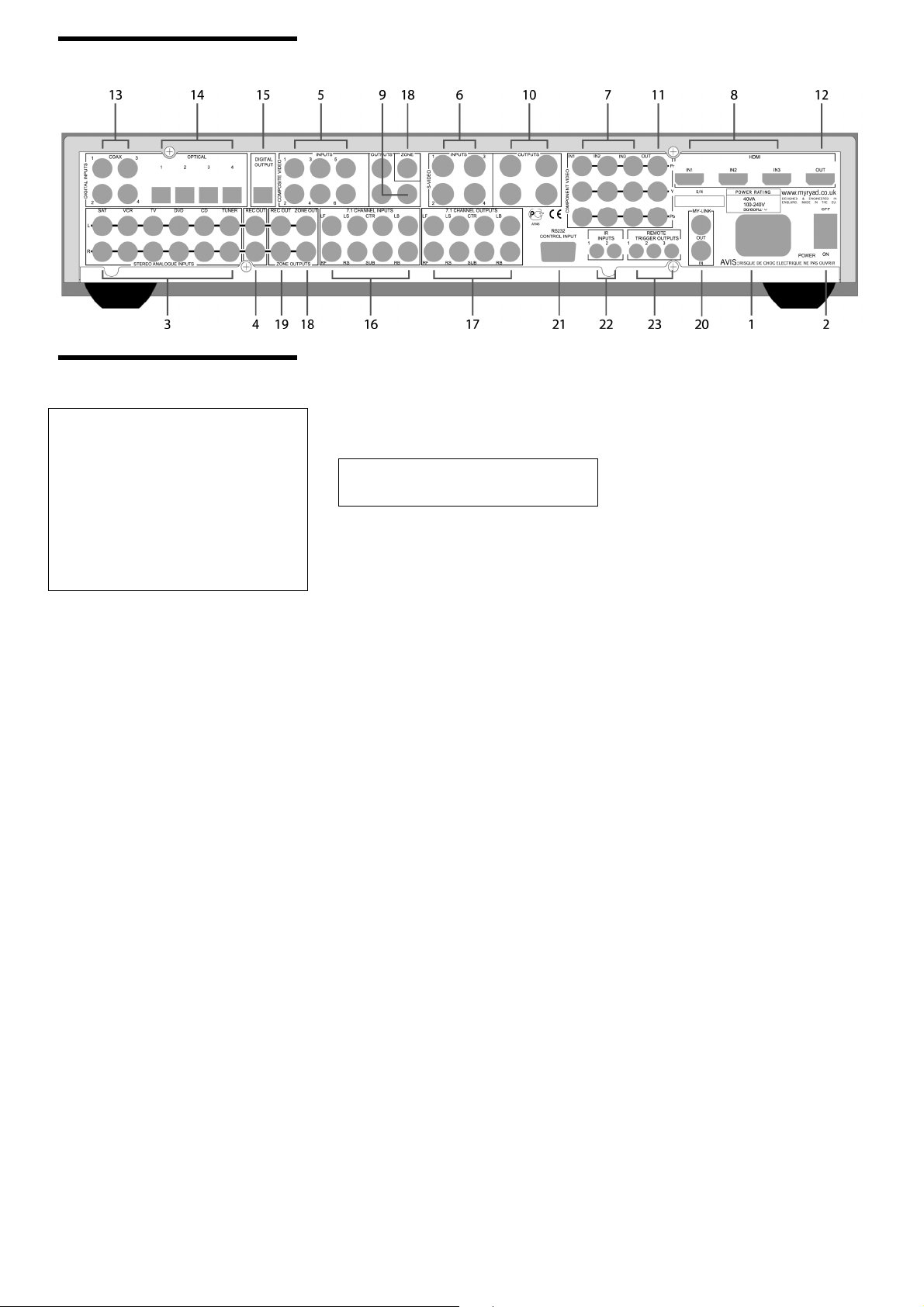
SETTING UP YOUR SYSTEM
REAR PANEL CONNECTIONS
CAUTION:
BEFORE MAKING ANY CONNECTIONS
TO YOUR MXD4000 MAKE SURE THAT
IT IS SWITCHED OFF AT THE REAR AND
THAT ITS POWER CORD IS
DISCONNECTED (EITHER AT THE WALL
SOCKET OR AT THE REAR OF THE
MXD4000). ALL EQUIPMENT BEING
CONNECTED TO THE MXD4000, EITHER
DIRECTLY OR INDIRECTLY, MUST
ALSO BE SWITCHED OFF BEFORE ANY
CONNECTIONS ARE MADE.
Failure to follow these precautions may
result in excessive ground currents flowing
briefly into the MXD4000 which can
permanently damage internal connections
and will invalidate your Warranty.
1. Power inlet
Before making any connection, check that
the mains voltage or range of voltages
printed on the rear panel includes your local
mains supply voltage.
Plug the female (socket) end of the power
cord into the power inlet on the rear of the
preamplifier. Plug the male (plug) end of
the cord into a "live" wall socket or a
suitable heavy duty extension cable.
Connect the MXD4000 only to a grounded
wall socket.
UK version only:
The mains plug is supplied fitted with a
fuse. It should only be replaced with a fuse
of the same rating which complies with
BS1362.
2. Power switch
Press bottom of this rocker switch to switch
the preamplifier ON and the top to switch it
OFF. When the POWER switch is in the
OFF position all power is disconnected
from the preamplifier. In this condition the
MXD4000 cannot be powered up from the
front panel or the remote control.
When the POWER switch is in the ON
position (and the power cord correctly
inserted and plugged into a live wall socket)
the MXD4000 will power up in standby
mode (see FRONT PANEL CONTROLS,
Standby on page 6).
It is recommended that the POWER switch
is turned OFF if the MXD4000 is not going
to be used for an extended period of time.
CAUTION: ALWAYS SWITCH THE
MXD4000 TO STANDBY BEFORE
SWITCHING THE POWER OFF.
3. Stereo analogue inputs
Connect the analogue audio output cables
of the appropriate devices to these sockets.
Always connect these inputs, even if you
may intend to listen only via the digital
inputs (for example in the case of a CD or
DVD player). This ensures that a signal will
always be present at the Record and Zone
outputs.
The signal from the ANALOGUE stereo
inputs is fed to an A-D converter that
converts the signal to digital format. The
signal can then be processed using Dolby
Pro Logic, Pro Logic II/IIx, DTS Neo:6 or
other modes. The signal is then fed to D-A
converters and thence to the 7.1 channel
line outputs. The selected signal is also fed
to the ANALOGUE Record and Zone
outputs.
[A-D = Analogue to Digital; D-A = Digital to
Analogue]
4. Record output (analogue)
The REC output carries the signal from
whichever ANALOGUE stereo source
device is currently selected (except sources
connected to the 7.1 CHANNEL input). This
output may be connected to the input of
any analogue recording device.
Note: When recording on an analogue tape
recorder, do not select the playback signal
from that recorder for listening. This will
create a feedback loop that may damage
your system.
The source selected for Zone B may be
used for recording via the ZONE REC
output – see section 19 below.
Video inputs
Video devices have outputs of different
types offering different levels of picture
quality. The MXD4000 can accept analogue
video inputs of three types, in increasing
order of quality: composite video, s-video
and component video - plus HDMI digital
video inputs.
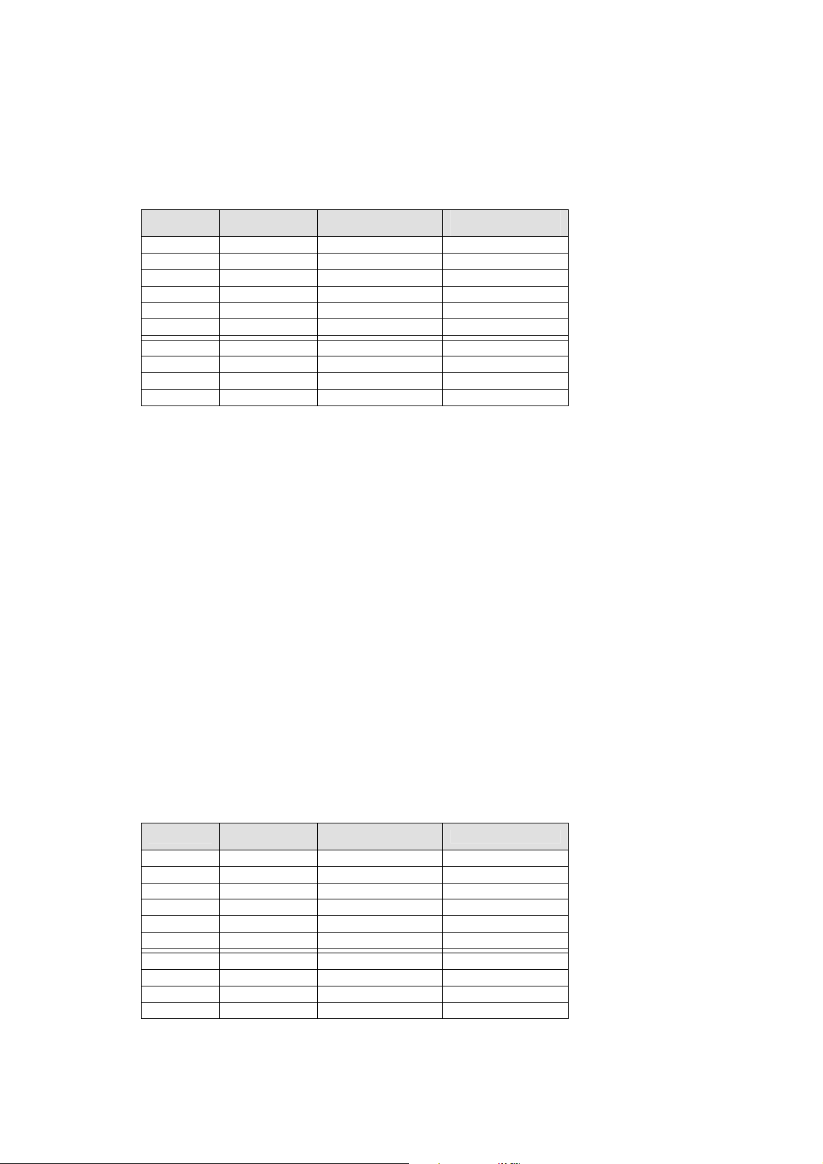
The MXD4000 allows each of its video
inputs to be “assigned” by the user to any
of its ten available sources using the
“Source setup” menu (page 14). The
MXD4000 is supplied set up as shown in
table 1 overleaf. These video assignments
apply to the main zone video outputs only.
The Zone B (composite only) assignments
are fixed as shown in the table.
Any selected composite or s-video input will
automatically be “up-converted” to the
higher-quality analogue video formats
(composite to s-video and component, svideo to component), allowing only a single
analogue video connection to be made to
the TV monitor at the highest quality
available. There is no up-conversion to the
HDMI (digital) format.
5. Composite video inputs
Connect the composite video output cables
from your video sources to these inputs.
The desired composite video signal may be
selected from these inputs, and is fed to
the COMPOSITE VIDEO outputs and/or
the ZONE video output.
6. S-video inputs
Connect the s-video output cables from
your video sources to these inputs. S-video
signals are of higher quality than composite
video signals. Therefore if your source
devices have s-video outputs it is
recommended that you use them, together
with the s-video inputs on your display.
S-video inputs are also automatically downmixed to feed the composite video outputs
for displays which do not have s-video
inputs – but this down-mixed composite
video is not available on the ZONE output.
3
7. Component video inputs
Connect the component video output
cables from your video sources to these
inputs (three RCA cables per source).
Component signals are of higher quality
than composite or s-video signals.
Therefore if your source devices have
component outputs it is recommended that
you use them, together with the component
video inputs on your display. Component
Source No.
Default
source name
1 SAT HDMI 1 Composite 1
2 VCR S-video 1 Composite 2
3 TV Composite 3 Composite 3
4 DVD HDMI 2 Composite 4
5 CD off Composite 5
6 TUNER off Composite 6
7 AUX 1 Component 1 none
8 AUX 2 Component 2 none
9 AUX 3 S-video 3 none
10 AUX 4 S-video 4 none
9. Composite video outputs
There are three COMPOSITE VIDEO
monitor outputs, all of which carry On
Screen Display (OSD) information when the
MENU or GUIDE function is activated.
Connect the composite video input of your
display device (TV) to one of the
COMPOSITE VIDEO outputs. Connect the
composite video input of your VCR to
another of the COMPOSITE VIDEO
outputs.
Any selected s-video signal will also be
down-mixed to COMPOSITE VIDEO
monitor outputs and so can be monitored in
composite format.
10. S-video outputs
There are four S-VIDEO monitor outputs,
all of which carry OSD information when
the MENU or GUIDE function is activated.
Connect the s-video input of your display
device (TV) to one of the S-VIDEO outputs.
Connect the s-video input of your VCR to
another of the S-VIDEO outputs. In
addition, any selected composite video
source will be “up-converted” to s-video so
that only a single s-video connection to the
TV is necessary.
Source No.
Default
source name
1 SAT yes Optical 1
2 VCR yes off
3 TV yes off
4 DVD yes Coax 1
5 CD yes Coax 2
6 TUNER yes Optical 2
7 AUX 1 no Coax 3
8 AUX 2 no Coax 4
9 AUX 3 no Optical 3
10 AUX 4 no Optical 4
If you re-assign any of the digital inputs to a different source. record this in table 7 on page 14.
You may assign a digital input to more than one source if desired.
video sources are not mixed down to svideo or composite, so there will be no
signal from these outputs.
The component video input-output path is a
direct high-quality signal path – fully
capable of carrying High Definition TV
signals without degradation. Component
video connectors are usually marked
“Y/Pb/Pr” or “Y/U/V” and are colour-coded
green, blue and red respectively.
Default main zone
video input
Zone B composite
video input (fixed)
11. Component video outputs
Connect these outputs to the component
video inputs of your display device (TV).
Any source selected which has been set up
for a component input will be sent directly
to these outputs. In addition, any selected
composite or S-video source will be “upconverted” to component video so that only
a single component video connection to the
TV is necessary. When the MENU or
GUIDE function is activated OSD
information will appear at the component
video outputs.
12. HDMI digital video output
Connect this output to the HDMI digital
video input of your display device (TV). If
your display only has a DVI digital video
input, you should use an HDMI-to-DVI
adaptor cable. Note: analogue video
sources (composite, s-video and
component video) will not be up-converted
to appear at the HDMI output. An analogue
video connection to the screen is
necessary to view these sources. OSD
information cannot be viewed on the HDMI
output.
Analogue
Stereo input?
Default digital input
8. HDMI digital video inputs
Connect the HDMI video output cables
from your video sources to these inputs.
HDMI video sources are only available from
the HDMI output.
Note: the audio signal carried on the HDMI
cable will be sent to the HDMI output, but is
not linked into the MXD4000 for processing.
A separate “SPDIF” digital audio input must
be used (optical or coaxial).
Table 1
Default video input
assignments
13. Coaxial digital audio inputs
Connect the coaxial digital output cables
from your source devices to these inputs.
The digital inputs can be freely assigned to
any analogue audio source or one of the
digital/video-only sources, AUX1-4 (see
Source setup menu for further reference),
but the MXD4000 is supplied set up as
shown in the table 2 below.
14. Optical digital audio inputs
Connect the Optical Digital audio cables
from your source devices to these inputs.
The optical digital inputs can also be freely
assigned to any source, but the MXD4000
is supplied set up as shown in the table 2
below.
Note: The “SPDIF” digital interface is
sensitive to the quality of connection when
using 96kHz sample rate sources. Always
use a high quality digital optical or coaxial
interconnect for 24bit/96kHz.
Table 2
Default digital input
assignments
4
15. Digital output
Connect the optical input of your digital
recording device to the DIGITAL output.
The selected digital source is fed to this
output in optical digital format.
16. 7.1 Channel inputs (Left Front, Right
Front, Left Surround, Right Surround,
Centre, Subwoofer, Left Back and Right
Back)
Connect the audio line outputs from any
multi-channel analogue source such as a
DVD-Audio player or Super Audio CD
(SACD) player to these inputs using up to
eight interconnect cables (or four stereo
cables) as necessary. The Left Back and
Right Back channels are provided for future
surround formats. The 7.1 CHANNEL
inputs may be used with any mono, stereo,
5.1 channel or 7.1 channel source.
You may use these inputs as an “Analogue
Direct” input to bypass the digital section of
the MXD4000 (use Left Front and Right
Front for a stereo source). The record and
zone outputs are not active when the 7.1
channel input is selected.
17. 7.1 Channel outputs – (Left Front,
Right Front, Left Surround, Right
Surround, Centre, Subwoofer, Left Back
and Right Back)
Connect these outputs to the line inputs of
your power amplifier(s). The SUB output
will normally be fed to the low-level Line
Input of an active subwoofer. Alternatively it
may feed a separate power amplifier and
passive subwoofer.
If your setup has only one rear speaker, its
power amplifier should be connected to the
Left Back output.
18. Zone B audio and composite video
outputs
These connectors carry the stereo
analogue audio and composite video
signals selected for Zone B. The MXD4000
allows you to feed separate audio or audiovideo programmes to two different areas, or
zones, in your home. To feed video and
audio to a second zone (Zone B), connect
a composite video cable to the “ZONE”
composite video output and a pair of audio
cables to the “ZONE OUT” audio
connectors. On Screen Display information
is not added to the ZONE video output. The
“ZONE” audio output is always stereo
(unless you are playing a monophonic
source). See “Zone B operation” section on
page 18 for full details of how the second
Zone operates.
19. Zone B audio record output
The zone REC OUT output carries the
same signal as the ZONE OUT, but at a
fixed volume level. It can be used for
recording audio onto a VCR or tape
recorder.
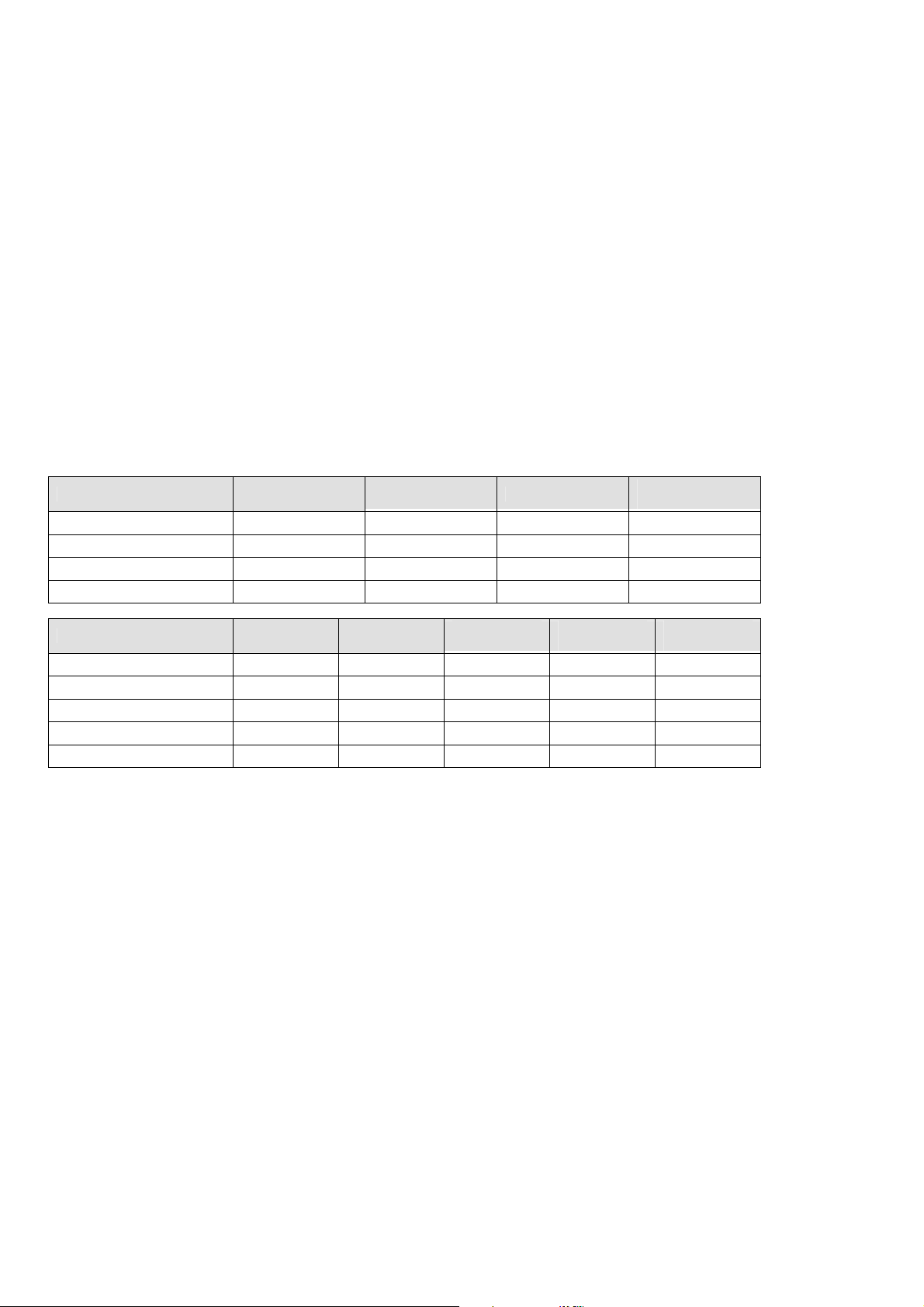
Tables 3 and 4 summarising available input/output connections and signal routing
Audio input/output
7.1 channel
line outputs
REC output Digital output
Zone audio and
rec outputs
Available from
Stereo analogue inputs Yes Yes No Yes
Digital inputs Yes No Yes No
7.1 channel analogue inputs Yes No No No
Video input/output
Available from
Composite
video outputs
S-video
outputs
Component
video output
HDMI video
output
Zone video
Composite video in Yes Yes Yes No Yes
S-video in Yes Yes Yes No No
Component video in No No Yes No No
HDMI video in No No No Yes No
20. Smart My-Link® input/output
When the MXD4000 is used in a system
with other Myryad M-Series products, all
may be joined together via the Smart MyLink®. The output of the MXD4000 should
be connected to the My-Link input of the
next product and its My-Link output
connected to the My-Link input of the next
and so on in “daisy-chain” fashion. This
inter-linking provides four main benefits.
Firstly, when the MXD4000 is switched out
of (or into) STANDBY, either using the front
panel ellipse or the remote control, all the
other linked Myryad products will switch out
of (or into) STANDBY at the same time.
Note: there is a short processing delay
(about 1.5 seconds) between the MXD4000
switching into STANDBY and the Smart
My-Link® control pulse switching the other
linked units into STANDBY.
Secondly, only one linked product with its
own Infra Red receiver (e.g. a Myryad CD
player, but not a Power Amplifier) needs to
be “in line of sight” of the remote handset.
The Smart My-Link® will carry the remote
command from any IR receiver to all the
other products that are linked together.
Thirdly, when linked to other Myryad Smart
My-Link® equipped products, more
powerful system features are available (see
“System Operation with Smart My-Link® on
page 15).
Finally, the Smart My-Link® may be used
to interface with various proprietary multiroom control systems. Contact your Myryad
dealer or Armour Home Electronics Ltd. for
details or visit the Myryad website at
www.myryad.co.uk.
21. RS 232 control interface
You can connect the MXD4000 to a home
automation system through this interface.
Contact your Myryad dealer or Armour
Home Electronics Ltd. for details or visit the
Myryad website at www.myryad.co.uk.
22. IR remote inputs
These two 3.5mm jacks accept remote
control signals relayed from remote IR
receivers or sensors. Using a remote IR
sensor allows the MXD4000 to be
controlled when installed in a cabinet with
closed doors, or from another room. The IR
inputs are compatible with Xantech IR
repeater products – for example the 291
series IR sensor via the CB12 connecting
block.
It is recommended that the MXD4000 and
any remote sensors are positioned such
that the two cannot receive IR signals from
the remote handset at the same time,
otherwise the MXD4000 may not respond
correctly to some commands.
23. Remote trigger outputs – 1, 2 and 3
You can connect the DC trigger inputs of
any audio or other equipment to these
TRIGGER outputs using 3.5mm jack plugs.
The TRIGGER outputs may be activated
when the MXD4000 is switched out of
STANDBY and turned off again
immediately when the MXD4000 is
switched back into STANDBY. The
TRIGGER outputs may also be
programmed to be activated under other
conditions (see Trigger setup menu
section, page 15).
The TRIGGER outputs deliver +12V DC
with a maximum current of about 40mA
from each of the three trigger outputs.
CAUTION: THE TRIGGERS SHOULD
ONLY BE CONNECTED OR
DISCONNECTED WHEN THE POWER
SWITCH IS OFF, OR THE UNIT IS
DISCONNECTED FROM MAINS POWER.
5
output
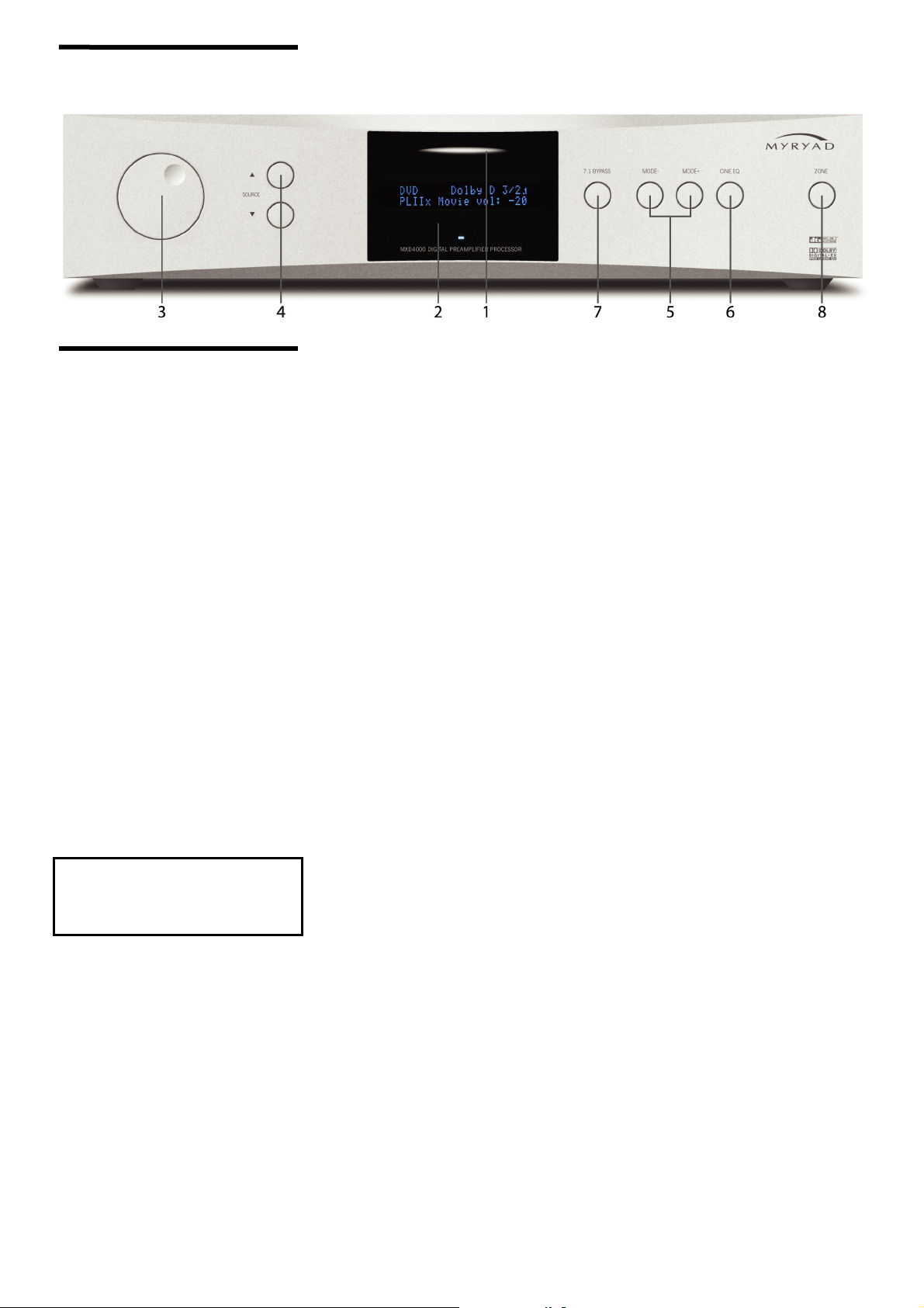
OPERATING YOUR SYSTEM
FRONT PANEL CONTROLS
1. Standby
When the preamplifier is plugged into a live
wall socket and the POWER switch is
turned ON, the display will remain blank for
about 4 seconds. Then the LED (Light
Emitting Diode) above the product name
will glow blue for 5 seconds while the
processor powers up. Finally the LED will
change to red indicating that the MXD4000
is now in standby mode, with its internal
circuitry powered up but inactive.
When the STANDBY ellipse is touched the
preamplifier circuitry will be activated and
the last used INPUT and last used MODE
automatically selected. The display will
briefly read “Myryad MXD4000 Initialising”
and the LINE outputs will remain muted for
a few seconds. During this delay period the
blue LED in the display will flash to indicate
this mute condition.
When the STANDBY ellipse is touched
again the preamplifier will be returned to
standby mode, the display will briefly read
“Myryad MXD4000 Shutting down” and the
LED in the display will glow red again.
CAUTION: always switch the MXD4000 to
STANDBY before switching the POWER
off at the rear to save control settings and
to avoid loud noises through the
loudspeakers.
CAUTION: WHEN IN STANDBY MODE
THE INTERNAL CIRCUITRY OF THE
MXD4000 IS STILL LIVE, SO ALL
SAFETY PRECAUTIONS MUST BE
FOLLOWED.
2. Display
Located behind this window is a high
quality blue Vacuum Fluorescent Display
(VFD) which indicates the operating
condition of the MXD4000 – including the
selected input, operating mode and volume
setting. Also behind this window (and
located to the left of the standby ellipse) is
the Infra-Red detector which receives
commands from the remote control
handset.
3. Volume control
The volume control adjusts the sound level
of the signal fed to the 7.1 CHANNEL line
outputs. It does not affect the signals fed to
the REC output sockets so it can safely be
adjusted whilst making a recording.
The volume setting is indicated in the
bottom right of the VF display, for example
“vol: -35”. The display indicates the
preamplifier gain in dB (decibels)
referenced to THX standard gain (-2.5dB).
When first switched on the volume is set
automatically to –20, which is a typical
listening level. If the volume is set below –
20 this will be remembered when the
MXD4000 is switched into STANDBY and
re-instated when it is switched on again. If
the unit is switched to STANDBY with a
volume setting higher than –20, it will be
reset to –20 when switched on again to
protect against excessive sound levels.
The volume control range is from -90dB to
+8dB when all channel level adjustments
(e.g. in the Speaker level or Audio setup
menus) are set to zero or negative values.
If any of these adjustments is set to a
positive figure, the maximum volume
setting is reduced by the same amount to
prevent possible digital overload. The
maximum volume setting is also reduced in
some digital processing modes.
When the volume level is being changed
(using the front panel control or the
remote), there may be small “ticking”
sounds at each volume step. These will be
more noticeable at higher volume settings.
These noises are quite normal and have no
effect upon the sound quality once the
volume control has been set.
4. Source select and
These buttons scroll up or down through
the inputs to select which of the ten
sources is fed to the main outputs for
listening and viewing. The display shows
which input has been selected. When an
analogue stereo audio and/or composite
video source is selected, the same signal
will also be fed to the REC output sockets
for recording.
When an input is selected, the MXD4000
will automatically switch to the operating
MODE last used with that input, or to the
correct digital decoding if an active digital
source is assigned to the input.
5. Mode+ and Mode- buttons
The MODE+/- buttons are used to cycle
through the available processing modes for
analogue stereo and digital sources (no
processing is possible for the 7.1 channel
analogue input). Not all modes are possible
for all types of signal source. Table 5
opposite lists the possible options in the
order in which they are selected.
6
 Loading...