

Myryad MT-100 Owners manual
Myryad Systems Ltd
MT 100 FM Stereo Tuner
2 Piper’s Wood
Waterberry Drive
Waterlooville PO7 7XU
Tel +44 (0) 23 9226 5508
Fax +44 (0) 23 9223 1407
info@myryad.co.uk
For further information,
please contact
Myryad direct or visit:
www.myryad.co.uk
mt 100
FM Stereo Tuner
Owner’s manual
content
power
on
off
my-link
out in
rl
line
output
input
antenna
coax
75Ω
• Introduction 2
• Installation and safety notes 2
• Accessories 2
• Setting up your system 3
• Rear panel connections 3
• Operating your system 5
• Front panel controls 5
• Remote control 6
handset operation
• Antenna 7
• Trouble-shooting guide 7
• Spefications 7
introduction
The Myryad MT 100 FM Stereo Tuner has
been designed to offer a combination of
high quality sound reproduction, ease of use
and elegant styling in keeping with other
Myryad products.
The MT 100 is a full-function remotecontrollable FM Stereo Tuner. It has
fixed-level low-impedance audio outputs
to feed a Myryad integrated amplifier or
preamplifier – or other high quality amplifier.
A coaxial antenna socket is provided for a
75Ω FM radio (Band 2) antenna. In addition
the MT 100 has a “My-Link” control input
and output for communication with other
Myryad products.
The MT 100 offers a range of expansion
possibilities:
• The MT 100 can be remote-controlled
using the Myryad System Remote handset.
• The “My-Link” input can be connected
to a Myryad integrated amplifier or
pre-amplifier so that the MT 100 will
automatically be switched on or off when
the amplifier is switched on or off.
• The “My-Link” input/output can be
coupled to other Myryad products, which
can then be remote-controlled via the
MT 100's infra-red receiver – or vice-versa.
installation and
safety notes
This Tuner generates very little heat but still
requires some ventilation. Do not place it
on a rug or other soft surface into which it
could sink, obstructing the air inlets in its
underside. Do not allow any obstruction to
the ventilation slots in the rear panel. The
Tuner should not be placed in a built-in
installation such as a bookcase or rack unless
proper ventilation is provided.
CAUTION:TO PREVENT A FIRE OR SHOCK
HAZARD, DO NOT PERMIT THIS PRODUCT TO
BECOME WET. IF LIQUID IS ACCIDENTALLY
SPILLED ON IT,IMMEDIATELY SHUT OFF ITS
POWER AT THE WALL SOCKET AND UNPLUG
THE AC POWER CORD.ALLOW SUFFICIENT
TIME FOR COMPLETE EVAPORATION TO OCCUR
BEFORE OPERATING THE UNIT AGAIN. IF THE
LIQUID IS ANYTHING BUT WATER AND/OR
ALCOHOL,THE UNIT SHOULD BE EXAMINED
BY A QUALIFIED SERVICE TECHNICIAN BEFORE
IT IS USED AGAIN.
Do not remove the cover, or attempt to
modify or repair the Tuner yourself.
Refer all servicing to a qualified technician.
NOTE REGARDING MICROPROCESSOR
CONTROLLED EQUIPMENT:
ALL MYRYAD M-SERIES PRODUCTS ARE
CONTROLLED BY A MICROPROCESSOR
LOCATED BETWEEN THE FASCIA AND SUBFASCIA.THESE PROCESSORS RUN WHENEVER
THE UNIT IS TURNED ON AT THE REAR PANEL.
LIKE ALL MICROPROCESSORS, THOSE USED
IN MYRYAD EQUIPMENT ARE SENSITIVE TO
CHANGES IN SUPPLY VOLTAGE. IN PARTICULAR,
WHEN THE UNIT IS TURNED OFF AT THE REAR
PANEL SWITCH, THE PROCESSOR MUST BE
GIVEN TIME TO RESET BEFORE THE UNIT IS
TURNED BACK ON. GENERALLY 60 SECONDS
IS SUFFICIENT. FAILURE TO ALLOW TIME FOR
THE PROCESSOR TO RESET MAY RESULT IN
INCORRECT PROCESSOR OPERATION.
SYMPTOMS OF THIS MIGHT INCLUDE:
• BUTTONS THAT FAIL TO WORK.
• UNEXPECTED ACTIONS ETC.
THIS IS COMMON TO ALL MICROPROCESSOR
CONTROLLED EQUIPMENT BUT CAN BE
AVOIDED BY TAKING THE FOLLOWING STEPS:
• MYRYAD UNITS ARE DESIGNED TO BE LEFT
IN STANDBY FOR LONG PERIODS – YOU
DON’T NEED TO TURN THEM OFF AT THE
BACK PANEL UNLESS YOU EXPECT THEM
TO BE UNUSED FOR EXTENDED PERIODS
OF TIME.
• IF YOU TURN YOUR UNIT OFF AT THE REAR
PANEL, ALLOW 60 SECONDS TO ELAPSE
BEFORE TURNING IT BACK ON.
• IF PROBLEMS DO OCCUR, TURN OFF YOUR
UNIT AND LEAVE IT TO STAND FOR AT LEAST
60 SECONDS. IF THE PROBLEMS RECUR
WHEN YOU TURN THE UNIT BACK ON,
CONTACT YOUR DEALER.
accessories
Your MT 100 is supplied complete with
the following accessories:
• Separate mains power cord to suit
country of sale.
• Wire antenna (300Ω) suitable for high
signal strength areas.
• Balun (matching adaptor) to allow
connection of the 300Ω antenna.
• Balun interface connector where necessary
(not all countries).
• System Remote.
setting up your
system
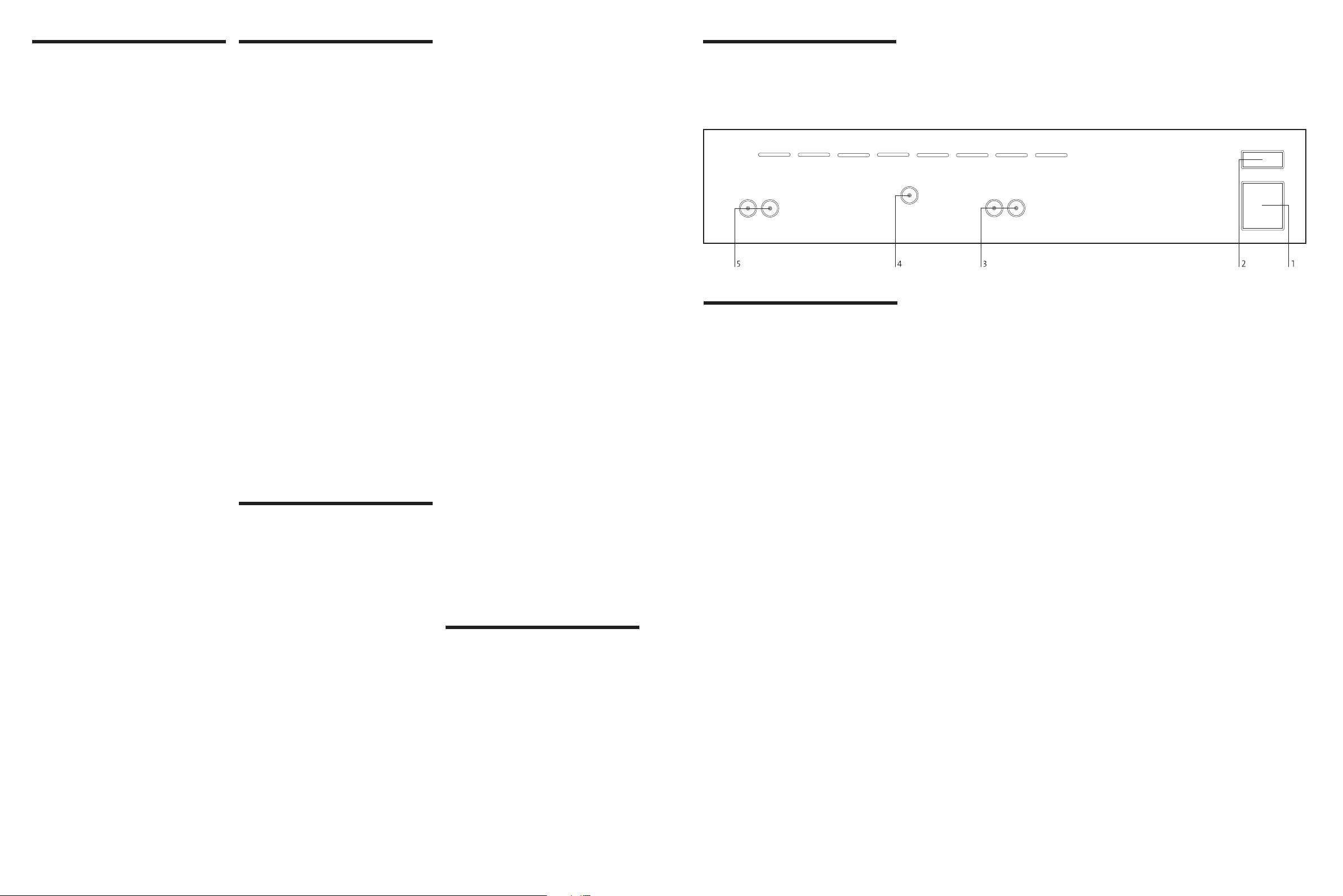
rear panel
connections
1 Power inlet
Before making any connection, check that the
mains voltage setting printed on the rear
panel is the same as your local mains supply.
Plug the female (socket) end of the power
cord into the power inlet on the rear of the
Tuner. Plug the male (plug) end of the cord
into a “live” wall socket or a suitable heavy
duty extension cable.
UK version: The mains plug is supplied fitted
with a 5A fuse. It should only be replaced
with a fuse of the same rating (5A) which
complies with BS1362.
Plug wiring instructions: The wires in this
mains lead are coloured in accordance with
the following code:
• blue – neutral
• brown – live
As the colours of the wires in the mains lead
of this apparatus may not correspond
with the coloured markings identifying the
terminals in your plug, proceed as follows:
• The wire that is coloured blue must be
connected to the terminal that is marked
with the letter N or coloured black.
• The wire that is coloured brown must be
connected to the terminal that is marked
with the letter L or coloured red.
No connection should be made to the
earth terminal of a three-pin plug (marked
with the letter E or coloured green or green
and yellow).
2 Power switch
Press one side of this rocker switch (the side
nearer the edge of the rear panel) to switch
the Tuner ON and the other side (towards
the antenna socket) to switch it OFF. When
the POWER switch is in the OFF position all
power is disconnected from the Tuner. In
this condition the Tuner cannot be powered
up from the front panel or the remote
control. When the POWER switch isin the
ON position (and the power cord correctly
inserted and plugged in to a live wall socket)
the Tuner will power up in standby mode
(see FRONT PANEL CONTROLS, STANDBY,).
It is recommended that the POWER switch
is turned OFF if the Tuner is not going to be
used for an extended period of time.
3 My-link input/output
When the MT 100 is used in a system with
other Myryad products all may be joined
together via the My-Link and this offers three
benefits. First, when coupled to a Myryad
Integrated Amplifier (e.g. the MI 120) or
Pre-amplifier, the MT 100 will automatically
be switched into or out of STANDBY when
the amplifier is switched on, either from the
front panel, or its own remote control.
Secondly, the My-Link allows both the
MT 100 and the Myryad Amplifier to be
remote-controlled via the infra-red receiver
in either unit. Thus only one unit needs to
be in “line-of-sight” of the remote handset.
Finally, the system enables the remote
control of some Myryad products that do
not have their own infra-red receiver.
When connected to a Myryad Integrated
Amplifier or Pre-amplifier via the My-Link,
the tuner display will show the message
“SYSTEM ON” during the five-second
warm-up period.
4 Antenna input
The MT 100 is fitted with a 75Ω “coaxial”
antenna socket, which must be used with a
75Ω antenna (aerial). The MT 100 is supplied
with a simple wire 300Ω antenna together
with an impedance matching adaptor
(see Figure 1). This antenna is provided to
ensure that the tuner can be set up and used
straight “out of the box”. It is not adequate to
provide full performance from the Tuner
except in areas of particularly high signal
strength (e.g. close to the FM transmitter). In
most instances a good quality roof or loft
mounted FM antenna should be used – see
“Antennas” section on page 7.
The MT 100 has different coaxial antenna
sockets to suit different countries. “North
American” models are fitted with “F” type
coaxial connectors while models for most
other countries are fitted with “DIN” style
connectors. When using the 300Ω wire
antenna the matching adaptor (or balun)
must be used and “DIN” versions also need
to be fitted with the female-to-female adaptor
supplied. See Figure 1 for clarification.
When you unfold the wire antenna you
will note that it is in the form of a “T”.
The “crossbar” portion of the T should be
stretched out horizontally and tacked in
place, either on a wall or the back of a
cabinet, or on the ceiling. The “vertical”
section of the T goes to the tuner’s antenna
input via the balun (see Figure 1). Experiment
with the position and orientation of the
antenna to obtain the best reception.
2
3
 Loading...