

Myryad MP-100 Owners manual

Myryad Systems Ltd
MP 100 Stereo Preamplifier
2 Piper’s Wood
Waterberry Drive
Waterlooville PO7 7XU
Tel +44 (0) 23 9226 5508
Fax +44 (0) 23 9223 1407
info@myryad.co.uk
For further information,
please contact
Myryad direct or visit:
www.myryad.co.uk
mp 100
Remote Controlled Stereo Preamplifier
Owner’s manual
contents
play
rec
aux
tuner
cd
video
gnd
tape 2
tape 1
play
rec
r l rl
power
onoff
9
10
11
12
introduction
installation and
setting up your
• Introduction 2
• Installation and safety notes 2
• Accessories 2
• Setting up your system 3
• Rear panel connections 3
• Operating your system 5
• Front panel controls 5
• Line output muting 6
• Remote control 6
handset operation
• Installing and 6
replacing batteries
• Trouble-shooting guide 7
• Spefications 7
2
The Myryad MP 100 Stereo Preamplifier
has been designed to offer a combination
of high quality sound reproduction and
elegant styling.
The preamplifier can accept up to six
line-level input sources, including two tape
recorders. Three pairs of line outputs are
provided (one pair Z-balanced) and a
headphones output. All functions – input
selection, volume and standby – can be
operated using the infra-red remote
control handset.
The MP 100 offers a range of expansion
possibilities:
• The AUX. input can be converted to
accept the output from a phono
cartridge by installing a Myryad Phono
Cartridge Pre-Amp Module.
• The three sets of line outputs allow
easy connection in a wide variety
of multi-amplifier systems.
• The “My-Link” input/output can be
coupled to other Myryad products
which can then be remote-controlled
via the MI 120's infra-red receiver.
safety notes
This preamplifier generates very little heat
but still requires some ventilation. Do not
place it on a rug or other soft surface into
which it could sink, obstructing the air inlets
in its underside. Do not allow any obstruction
to the ventilation slots in the rear panel. The
MP 100 should not be placed in a built-in
installation such as a bookcase or rack unless
proper ventilation is provided.
CAUTION:TO PREVENT A FIRE OR SHOCK
HAZARD, DO NOT PERMIT THIS PRODUCT TO
BECOME WET. IF LIQUID IS ACCIDENTALLY
SPILLED ON IT,IMMEDIATELY SHUT OFF ITS
POWER AT THE WALL SOCKET AND UNPLUG
THE AC POWER CORD. ALLOW SUFFICIENT
TIME FOR COMPLETE EVAPORATION TO OCCUR
BEFORE OPERATING THE PREAMPLIFIER AGAIN.
IF THE LIQUID IS ANYTHING BUT WATER
AND/OR ALCOHOL,THE PREAMPLIFIER SHOULD
BE EXAMINED BY A QUALIFIED SERVICE
TECHNICIAN BEFORE IT IS USED AGAIN.
Do not remove the cover, or attempt to
modify or repair the preamplifier yourself.
Refer all servicing to a qualified technician.
accessories
Your MP 100 is supplied complete with
the following accessories:
• Separate mains power cord to suit
country of sale.
• System remote control handset.
• Four AAA batteries for handset
(not in some countries).
system
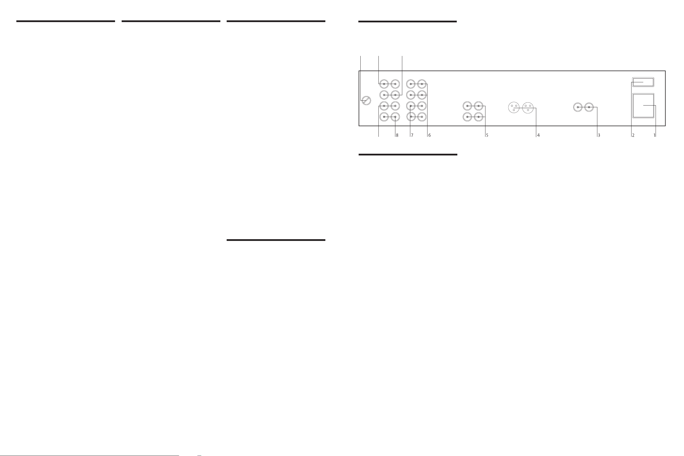
3 My-link input/output
rear panel
connections
1 Power inlet
Before making any connection, check that
the mains voltage setting printed on the rear
panel is the same as your local mains supply.
Plug the female (socket) end of the power
cord into the power inlet on the rear of the
preamplifier. Plug the male (plug) end of
the cord into a “live” wall socket or a suitable
heavy duty extension cable.
UK version: The mains plug is supplied fitted
with a 5A fuse. It should only be replaced
with a fuse of the same rating (5A) which
complies with BS1362.
2 Power switch
Press one side of this rocker switch (the side
nearer the edge of the rear panel) to switch
the preamplifier ON and the other (towards
the audio connectors) to switch it OFF. When
the POWER switch is in the OFF position all
power is disconnected from the preamplifier.
In this condition the preamplifier cannot be
powered up from the front panel or the
remote control. When the POWER switch
is in the ON position (and the power cord
correctly inserted and plugged in to a live
wall socket) the preamplifier will power up
in standby mode (see FRONT PANEL
CONTROLS, STANDBY, page 5).
It is recommended that the POWER switch
is turned OFF if the preamplifier is not going
to be used for an extended period of time.
When the MP 100 is used in a system with
other Myryad products all may be joined
together via the My-Link. This will allow
all the different products to be remotelycontrolled via the infra-red receiver on the
MP 100. My-Link offers two benefits. Firstly,
only the MP 100 infra red receiver needs to be
in “line-of-sight” from the remote handset.
Secondly, the My-Link allows remote control
of some Myryad products which do not have
their own infra-red receiver.
4 Line outputs 3, Z-balanced (XLR jacks)
These outputs are designed to feed power
amplifiers fitted with balanced inputs. They
are wired “Z-balanced” which means that
the “cold” line impedance (pin 3) precisely
matches that of the “hot” line (pin 2), but
the “cold” line carries no signal. This allows
full benefit to be gained from all the
interference and ground loop rejection
capabilities of the power amplifier’s balanced
inputs without the additional circuitry (and
resulting signal degradation) of push-pull
outputs. For more information on how the Zbalanced system works, please ask for a copy
of the Myryad white paper on this subject,
or visit www.myryad.co.uk/technology.html.
5 Line outputs 1 and 2 (RCA phono jacks)
These two outputs carry exactly the same
signals and are both wired “unbalanced”.
In a normal preamp/power amp system,
use the Line 1 outputs to drive the inputs
of your stereo power amplifier (such as the
Myryad MA 120). In a “bi-amplifier” system
connect the Line 1 outputs to one stereo
power amplifier (driving e.g. the treble
sections of the loudspeakers) and connect
the Line 2 outputs to the second stereo power
amplifier (driving the bass sections of the
loudspeakers). For more information on
this and other multi-amplifier systems with
Myryad products, please ask for a copy of
the Myryad white paper on this subject, or
visit www.myryad.co.uk/technology.html.
6 Tape 1 input/output
These connectors are suited to any type
of tape recorder, including high-quality
“3-head” types which allow you to monitor
the signal off the tape whilst it is being
recorded. Connect a stereo cable from the
TAPE 1 REC output sockets of the preamplifier to the LINE IN or RECORD IN
sockets on your tape deck. Connect a second
stereo cable from the TAPE 1 PLAY input
sockets of the preamplifier to the LINE OUT
or PLAY OUT sockets on your tape deck.
Any source selected for listening on the MP
100 will automatically be fed to the TAPE 1
REC output sockets for recording. If the TAPE
2 input is selected then tape copies may
be made from TAPE 2 to TAPE 1. It is NOT
possible to copy from TAPE 1 to TAPE 2.
7 Tape 2 input/output
These connectors are suited to any type
of tape recorder, but “off-tape” monitoring
is not possible using TAPE 2. The wiring from
TAPE 2 to your tape deck is identical to the
TAPE 1 wiring described above.
Any source selected for listening, except TAPE
1, will automatically be fed to the TAPE 2
REC output sockets for recording. It is NOT
possible to record from TAPE 1 to TAPE 2.
8 CD input
Connect the audio output cables from a CD
player to these sockets. (NOTE: this input is
for an audio signal, not for the digital output
3
 Loading...