

Myryad MI-120 Owners manual
Myryad Systems Ltd
MI 120 Integrated Amplifier
2 Piper’s Wood
Waterberry Drive
Waterlooville PO7 7XU
Tel +44 (0) 23 9226 5508
Fax +44 (0) 23 9223 1407
info@myryad.co.uk
For further information,
please contact
Myryad direct or visit:
www.myryad.co.uk
mi 120
Remote Controlled
Stereo Intregated Amplifier
Owner’s manual
contents
play
rec
aux
tuner
cd
video
gnd
tape 2
tape 1
play
rec
rl r l
power
onoff
bi-amp out
9
10
11
12
rl
out
in
my-link
introduction
installation and
setting up your
• Introduction 2
• Installation and safety notes 2
• Accessories 2
• Setting up your system 3
• Rear panel connections 3
• Operating your system 5
• Front panel controls 5
• Loudspeaker output protection 6
and muting
• Remote control handset operation 6
• Installing and replacing batteries 6
• Trouble-shooting guide 7
• Specifications 7
2
The Myryad MI 120 Stereo Integrated
Amplifier has been designed to offer
a combination of high quality sound
reproduction and elegant styling.
The amplifier can accept up to six line-level
input sources, including two tape recorders.
Outputs are provided for one pair of
loudspeakers and for headphones. All
functions – input selection, volume and
standby – can be operated using the infrared remote control handset.
The MI 120 offers a range of expansion
possibilities:
• The AUX. input can be converted to accept
the output from a phono cartridge by
installing a Myryad Phono Cartridge
Pre-Amp Module.
• A low-level “Bi-amp” output is provided
to feed the Myryad MA 120 Power
Amplifier, allowing bi-amplified drive
of suitable loudspeakers.
• The “My-Link” input/output can be
coupled to other Myryad products which
can then be remote-controlled via the
MI 120’s infra-red receiver.
safety notes
This amplifier generates a modest amount of
heat and thus requires ventilation. Do not
place it on a rug or other soft surface into
which it could sink, obstructing the air inlets
in its underside. Do not allow papers or cloth
to obstruct the ventilation grille in the top
cover. The amplifier should not be placed in
a built-in installation such as a bookcase or
rack unless proper ventilation is provided.
CAUTION:TO PREVENT A FIRE OR SHOCK
HAZARD, DO NOT PERMIT THIS PRODUCT TO
BECOME WET. IF LIQUID IS ACCIDENTALLY
SPILLED ON IT,IMMEDIATELY SHUT OFF ITS
POWER AT THE WALL SOCKET AND UNPLUG
THE AC POWER CORD.ALLOW SUFFICIENT
TIME FOR COMPLETE EVAPORATION TO OCCUR
BEFORE OPERATING THE AMPLIFIER AGAIN.
IF THE LIQUID IS ANYTHING BUT WATER
AND/OR ALCOHOL,THE AMPLIFIER SHOULD
BE EXAMINED BY A QUALIFIED SERVICE
TECHNICIAN BEFORE IT IS USED AGAIN.
Do not remove the cover, or attempt to
modify or repair the amplifier yourself.
Refer all servicing to a qualified technician.
accessories
Your MI 120 is supplied complete with the
following accessories:
• Separate mains power cord to suit
country of sale.
• Remote control handset.
• Four AAA batteries for handset
(not in some countries).
system
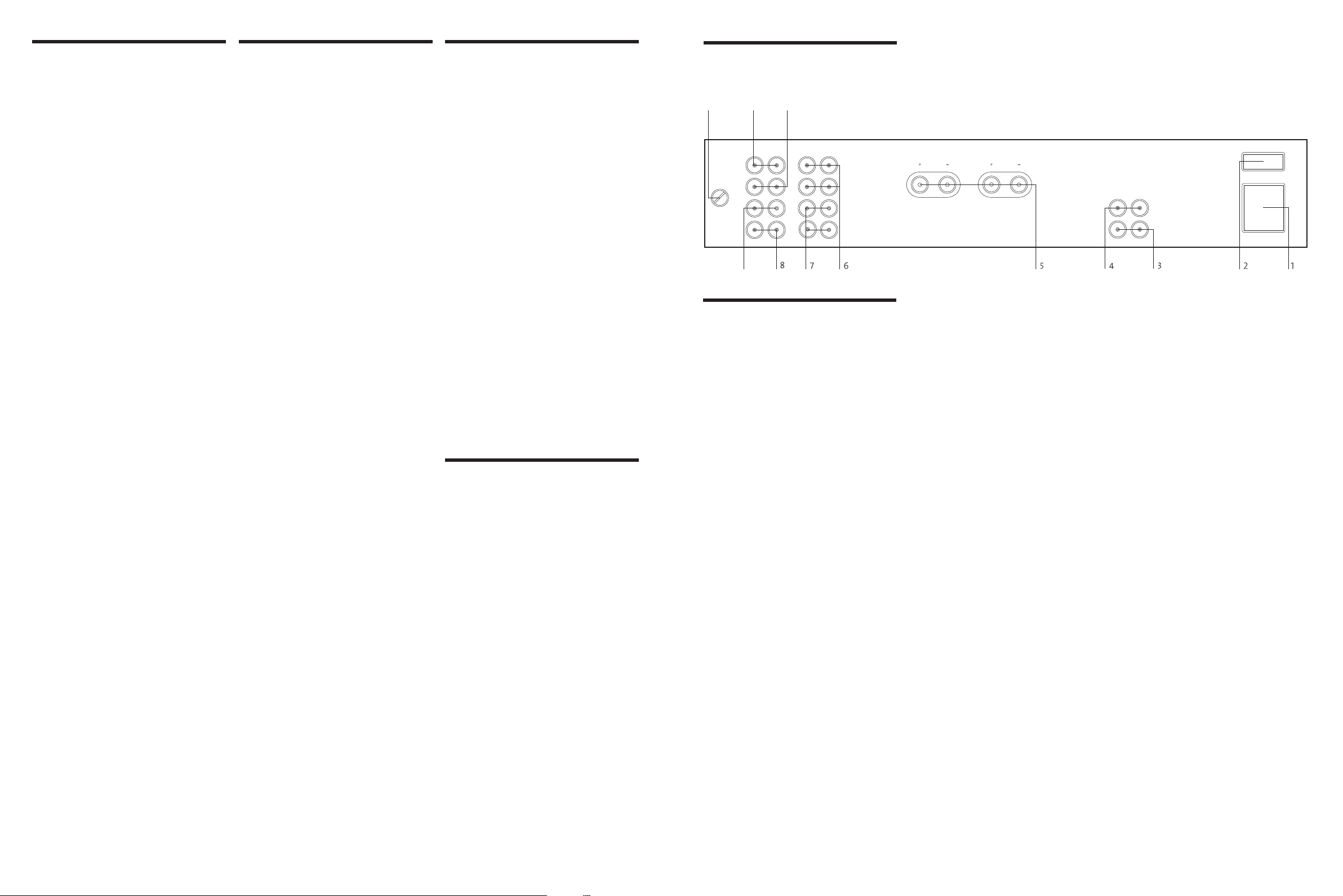
3 My-link input/output
rear panel
connections
1 Power inlet
Before making any connection, check that
the mains voltage setting printed on the rear
panel is the same as your local mains supply.
Plug the female (socket) end of the power
cord into the power inlet on the rear of the
amplifier. Plug the male (plug) end of the
cord into a “live” wall socket or a suitable
heavy duty extension cable.
UK version: The mains plug is supplied fitted
with a 5A fuse. It should only be replaced
with a fuse of the same rating (5A) which
complies with BS1362.
2 Power switch
Press one side of this rocker switch (the side
nearer the edge of the rear panel) to switch
the amplifier ON and the other side (towards
the speaker terminals) to switch it OFF. When
the POWER switch is in the OFF position
all power is disconnected from the amplifier.
In this condition the amplifier cannot be
powered up from the front panel or the
remote control. When the POWER switch
is in the ON position (and the power cord
correctly inserted and plugged in to a live
wall socket) the amplifier will power up
in standby mode (see FRONT PANEL
CONTROLS, STANDBY, page 5).
It is recommended that the POWER switch is
turned OFF if the amplifier is not going to be
used for an extended period of time.
When the MI 120 is used in a system with
other Myryad products all may be joined
together via the My-Link. This will allow
all the different products to be remotelycontrolled via the infra-red receiver on the
MI 120. My-Link offers two benefits. Firstly,
only the MI 120 infra red receiver needs to
be in “line-of-sight” from the remote handset.
Secondly, the My-Link allows remote control
of some Myryad products which do not have
their own infra-red receiver.
4 BI-AMP output
Many loudspeakers today are made so that
the bass and treble sections can be separated
and fed from two sets of speaker cables.
This is known as “bi-wiring” and can yield
a significant improvement in sound quality.
A further sound quality gain may be made
by “bi-amplifying” the loudspeaker – using
two separate power amplifiers to drive the
bass and treble sections.
The MI 120 makes provision for this
with its “BI-AMP” output, which can be
used to feed a separate MA 120 Power
Amplifier. The MI 120 loudspeaker outputs
should be connected to the bass sections
of the loudspeakers (left and right) while
the MA 120 drives the treble. This mode of
operation is described in more detail in
the MA 120 Owner’s Manual, or visit
www.myryad.co.uk/technology.html
5 Loudspeaker outputs
The loudspeaker outputs are capable of
driving all loudspeakers with rated
impedances in the range 4Ω to 16 Ω. The
loudspeaker terminals are high – current
binding – posts, coded red or black. The
terminals on the left side of the amplifier
(viewed from the front) and marked “L”
should be wired to the left hand loudspeaker.
Those on the right, marked “R”, should be
wired to the right hand loudspeaker.
For correct stereo imaging it is important that
the two loudspeakers are wired “in phase”.
To ensure correct phasing wire the black (–)
terminal on the amplifier to the black or “–”
terminal on the loudspeaker. The red (+)
terminal on the amplifier should be wired to
the red or “+” terminal on the loudspeaker.
The loudspeakers should be positioned
as recommended by the loudspeaker
manufacturer. The two loudspeakers should
always be placed at equal distances from
the main listening position and usually
spaced a similar distance apart. It is generally
best to keep the loudspeakers away from
room corners and many loudspeakers work
best away from all walls.
6 Tape 1 input/output
These connectors are suited to any type of
tape recorder, including high-quality “3-head”
types which allow you to monitor the signal
off the tape whilst it is being recorded.
Connect a stereo cable from the TAPE 1 REC
output sockets of the amplifier to the LINE IN
or RECORD IN sockets on your tape deck.
Connect a second stereo cable from the TAPE
1 PLAY input sockets of the amplifier to the
LINE OUT or PLAY OUT sockets on your
tape deck.
Any source selected for listening on the MI
120 will automatically be fed to the TAPE 1
REC output sockets for recording. If the
3
 Loading...