

Myryad MA-240 Owners manual

Myryad Systems Ltd
STANDBY
MA 120 Stereo Power Amplifier
2 Piper’s Wood
Waterberry Drive
Waterlooville PO7 7XU
Tel +44 (0) 23 9226 5508
Fax +44 (0) 23 9223 1407
info@myryad.co.uk
For further information,
please contact
Myryad direct or visit:
www.myryad.co.uk
ma 120/240/360
Power Amplifiers
Owner’s manual

contents
• Introduction 3
• Installation and safety notes 3
• Accessories 3
• Setting up your systems 4
• Rear panel connections 5
• Operating your system 7
• Front panel controls 7
• Loudspeaker output 7
protection and muting
• Trouble-shooting guide 8
• Appendix 9
• The MI 120 plus MA 120 in
“Bi-Amplified” Systems
• Using the MA 240 with an MI 120
or mixed MA 120s and MA 240s
with an MP 100 in Bi-Amp or
Tri-Amp systems
• The MI 120 plus MA 120s in
“Tri-Amplified” systems
• The MI 120 or MP 100 with one
or more 120s or MA 240s in
Multi-Room systems
• My-link 10
• Specifications 15
introduction
The Myryad MA 120, 240 and 360 Power
Amplifiers have been designed to offer
a combination of high quality sound
reproduction and simple yet elegant styling.
They can be used to provide power for high
quality stereo systems when partnered by a
suitable preamplifier such as Myryad’s MP
100, or with a Myryad integrated amplifier in
bi-amp or tri-amp systems. They can also be
used, in combination (e.g. one MA 240 Stereo
Power Amplifier plus one Myryad MA 360
Three Channel Power Amplifier), to power a
full-surround music or Home Cinema sound
system of the highest quality.
The MA 120 and MA 360 have unbalanced
line inputs plus directly linked line outputs,
all on RCA phono sockets.
The MA 240 also has unbalanced line inputs
plus directly linked line outputs, all on
RCA phono sockets but it in addition it has
balanced line inputs on professional quality
3-pin XLR sockets. Furthermore, the two
amplifier channels may be switched to
bridged-mono mode for increased power
output into a single 8Ω loudspeaker using a
rear panel switch.
All Myryad M-Series Power Amplifiers may
be controlled remotely via the My-Link
communications bus when used with other
Myryad M series products. The My-Link
allows remote control of standby and mute
functions. In addition to this, the MA 240
and MA 360 power amplifiers may be
switched into or out of standby remotely
using their DC trigger inputs.
MA 120 applications include:
• Stereo operation, delivering 2 x 60 watts
into 8Ω loudspeakers
• One MA 120 with an MI 120 Integrated
Amplifier in a bi-amplifier system
• Two MA 120s with an MP 100
Preamplifier in a bi-amplifier system
• Three MA 120s with an MP 100
Preamplifier in a tri-amplifier system
• Up to ten MA 120s and one MI 120 or
MP 100 in a multi-room system
MA 240 applications include:
• Stereo operation, delivering 2 x 120 watts
into 8Ω loudspeakers
• High power stereo operation with two
MA 240s – able to deliver 2 x 400 watts
into a minimum 8Ω load
• Stereo bi-amplifier operation with two
MA 240s, each delivering 2 x 120 watts into
8Ω loudspeakers
• Use in conjunction with the MA 360 Three
Channel Power Amplifier, delivering five
channels at 120 watts into 8Ω in Home
Cinema systems of the highest quality
MA 360 applications include:
• Use in conjunction with the MA 240 Stereo
Power Amplifier, delivering of five channels
at 120 watts into 8Ω in Home Cinema
systems of the very highest quality.
PLEASE NOTE:THIS OWNER’S MANUAL
DESCRIBES ALL THREE POWER AMPLIFIERS.
WHERE THE TEXT APPLIES TO ONLY ONE OR
TWO OF THE AMPLIFIERS THE APPLICABLE
MODEL NUMBER(S)APPEAR IN THE PARAGRAPH
HEADING. WHERE NO MODEL NUMBER IS
SPECIFIED IN THE PARAGRAPH HEADING THE
TEXT APPLIES TO ALL POWER AMPLIFIERS.
installation and
safety notes
This amplifier generates a modest amount
of heat and thus requires ventilation. Do
not place it on a rug or other soft surface
into which it could sink, obstructing the air
inlets in its underside. Do not allow papers
or cloth to obstruct the ventilation grille in
the top cover. The amplifier should not be
installed in a built-in situation such as
a bookcase or cabinet that may impede
the flow of air. If the amplifier is moved
shortly after operation take care not to touch
the heatsinks, which are accessible from
below, as they may be very hot. The amplifier
is designed for use in moderate climates.
CAUTION:TO PREVENT A FIRE OR SHOCK
HAZARD, DO NOT PERMIT THIS PRODUCT TO
BECOME WET OR EXPOSE IT TO DRIPPING OR
SPLASHING. DO NOT PLACE OBJECTS FILLED
WITH LIQUID, SUCH AS VASES, ON THE
AMPLIFIER. IF LIQUID IS ACCIDENTALLY SPILLED
ON IT, IMMEDIATELY SHUT OFF ITS POWER AT
THE WALL SOCKET AND UNPLUG THE AC
POWER CORD.ALLOW SUFFICIENT TIME FOR
COMPLETE EVAPORATION TO OCCUR BEFORE
OPERATING THE AMPLIFIER AGAIN. IF THE
LIQUID IS ANYTHING BUT WATER AND/OR
ALCOHOL, A QUALIFIED SERVICE TECHNICIAN
SHOULD EXAMINE THE AMPLIFIER BEFORE IT
IS USED AGAIN.
DO NOT PLACE NAKED FLAMES, SUCH AS
LIGHTED CANDLES ON THIS PRODUCT. DO
NOT REMOVE THE COVER, OR ATTEMPT TO
MODIFY OR REPAIR THE AMPLIFIER YOURSELF.
REFER ALL SERVICING TO A QUALIFIED
TECHNICIAN.
accessories
Your Myryad Power Amplifier is supplied
complete with the following accessories:
MA 120,MA 240 and MA 360
• Separate mains power cord to suit
country of sale.
MA 240 only
• Two “U”-shaped gold-plated XLR jumper
links. Supplied inserted into the
BALANCED input sockets. {If you remove
these links from the amplifier store them
in a safe place as they may be needed in
the future.}
2
3
setting up your
my-link
out in
rl
rl
power
onoff
input
line
output
balanced input
connections
unbal link
1
2
3
+
–
+
–
out
in
right channel
balanced
normal
+
–
out
in
left channel (mono)
balanced
normal
stereo
bridged
mono
rl
out
in
my-link
remote
trigger
out
in
35mm jack
tip +, sleeve –
4.5v - 24v dc
power
onoff
35mm jack
tip +, sleeve –
4.5v - 24v dc
out
in
channel
2 channel 1
out
in
channel
3
out
in
213
out
in
my-link
remote
trigger
out
in
power
on
off
systems
MA 120 Stereo Power Amplifier
MA 240 Stereo Amplifier
MA 360 Three Channel Power Amplifier
4
standby will also bring the Power Amplifier
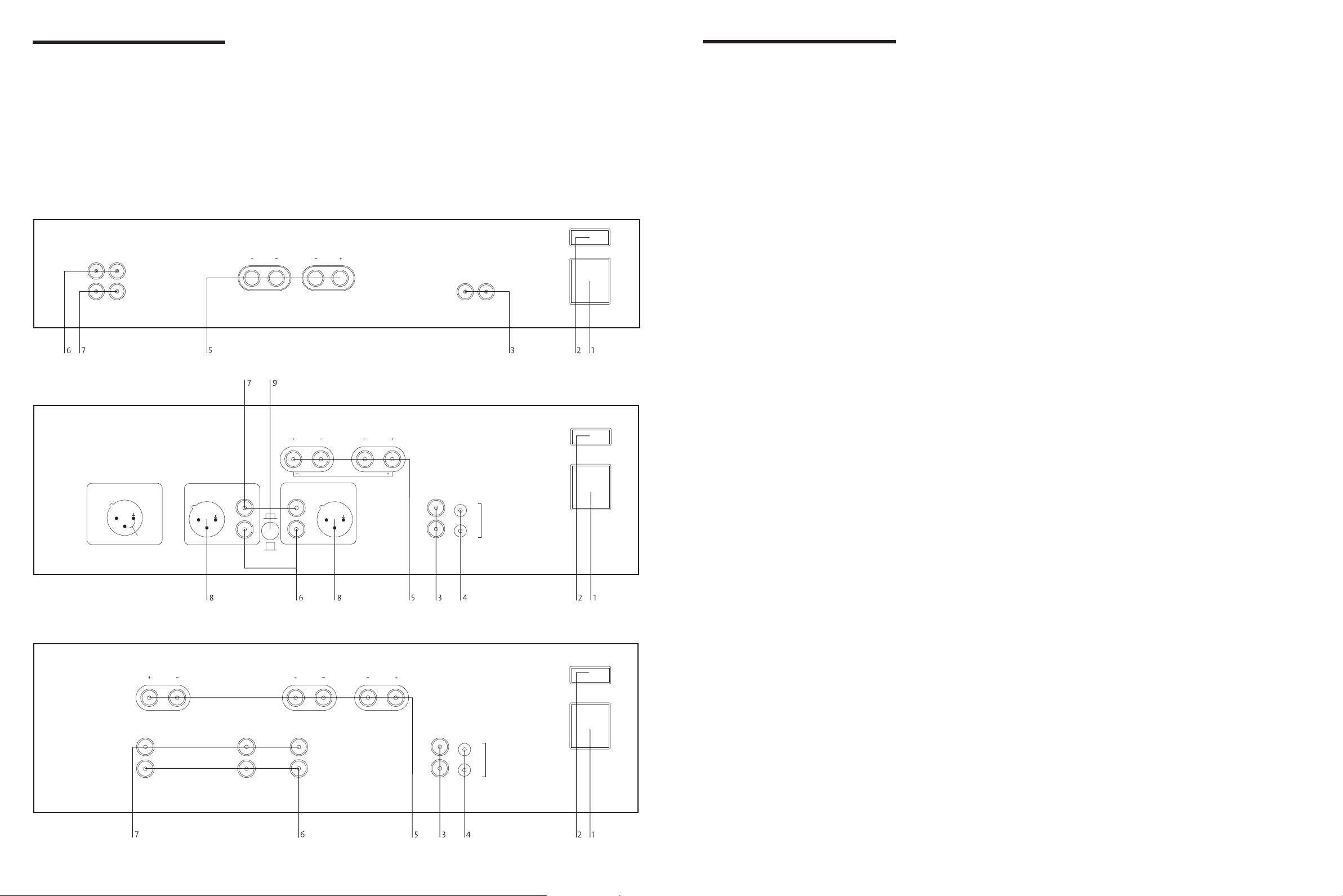
rear panel
connections
out of standby. In this way the MP 100 + MA
240 (or MA 120) can be operated with the
same ease as an integrated amplifier. If Power
Amplifiers are being used in a bi-amp or
1 Power inlet
Before making any connection, check that the
mains voltage setting printed on the rear
panel is the same as your local mains supply.
Plug the female (socket) end of the power
cord into the power inlet on the rear of the
tri-amp system all the amplifiers may be
My-Linked so that they can be controlled as
one from the Myryad preamplifier.
NOTE: SWITCHING THE POWER AMPLIFIER
INTO STANDBY WILL NOT SWITCH THE MP 100
PREAMPLIFIER INTO STANDBY.
amplifier. Plug the male (plug) end of the
cord into a“live” wall socket or a suitable
heavy-duty extension cable.
MA 240 and MA 360 only:
When the My-Link is connected it is
recommended that no connection be made to
UK version: The mains plug is supplied fitted
the REMOTE TRIGGER input (see below).
with a 5A fuse. It should only be replaced
with a fuse of the same rating (5A) which
complies with BS1362.
4 Remote trigger control input/output
(MA 240 and MA 360 only)
If the MA 240/360 is being used in a system
2 Power switch
Press one side of this rocker switch (the side
nearer the edge of the rear panel) to switch
amplifier ON and the other side (towards the
speaker terminals) to switch it OFF. When the
without a Myryad M-Series preamplifier,
processor or integrated equipped with MyLink, the REMOTE TRIGGER input may be
used to allow the MA 240/360 to be remotely
switched into or out of STANDBY.
POWER switch is in the OFF position all
power is disconnected from the amplifier. In
this condition the amplifier cannot be
powered up from the front panel or the MyLink (or remote trigger if present). When the
POWER switch is in the ON position (and
the power cord correctly inserted and plugged
in to a live wall socket) the amplifier will
power up in standby mode (see FRONT
PANEL CONTROLS, STANDBY,).
If your preamplifier or processor has a
TRIGGER output which delivers a DC trigger
signal when the unit is switched on (or out
of standby) then it can be linked to the
MA 240/360 to switch the MA 240/360 out
of/into standby also. A lead must be used
which is fitted with a 3.5mm mini-jack plug
to connect to the MA 240/360’s REMOTE
TRIGGER input socket. The lead must be
wired according to the rules below:
It is recommended that the POWER switch be
turned OFF if the amplifier is not going to be
used for an extended period of time.
• Connector to MA 240/360 REMOTE
TRIGGER input: 3.5mm mini-jack plug
• Jack plug wiring: sleeve negative,
tip positive
3 My-link input/output
When this Power Amplifier is used in a
system with other Myryad M-Series products
all may be joined together via the My-Link.
This will allow the different products to be
remotely controlled via the infra-red receiver
on, for example, an MP 100 Preamplifier. My-
• Trigger voltage: DC, 4.5V to 24V
• Nominal loading of MA 240/360
REMOTE TRIGGER input: 2200Ω
• TRIGGER voltage change from 0 to +ve:
Amplifier switched from standby to active
• TRIGGER voltage change from +ve to 0:
Amplifier switched from active to standby
Link offers two benefits. Firstly, only the MP
100 Preamplifier infra-red receiver needs to be
in “line-of-sight” from the remote handset.
Secondly, the My-Link allows remote control
of some Myryad products which do not have
their own infra-red receiver, such as the
Myryad Power Amplifiers.
When joined via the My-Link, the Power
Amplifier will respond to STANDBY and
MUTE operations on the MP 100 Preamplifier
i.e.: if both the MP 100 Preamplifier and the
Power Amplifier are in STANDBY, then
If you are in any doubt about meeting any of
these criteria or preparing a suitable lead, ask
your dealer or installer to handle this for you.
NOTE: IF THE TRIGGER INPUT IS ACTIVE
WHEN THE REAR PANEL POWER SWITCH IS
TURNED ON, THEN THE AMPLIFIER WILL
NOT POWER UP INTO STANDBY MODE AS
USUAL. IT WILL POWER UP IMMEDIATELY
INTO ITS “ACTIVE” STATE – WITH ITS NORMAL
POWER-ON MUTE DELAY (SEE FRONT PANEL
CONTROLS, STANDBY BELOW).
switching the MP 100 Preamplifier out of
The REMOTE TRIGGER output is wired
directly to the input. Using this output,
further MA 240/360s, or other products, may
be connected from a single trigger source
without needing any special adaptors.
5 Loudspeaker outputs
The loudspeaker outputs are capable of
driving all loudspeakers with impedances in
the range 4Ω to 16Ω (except the MA 240 in
Bridget-Mono – see below).The loudspeaker
terminals are high-current binding-posts,
coded red and black. The terminals on the
left side of the amplifier (viewed from the
front) and marked “L” should be wired to the
left hand loudspeaker. Those on the right,
marked “R”, should be wired to the right
hand loudspeaker.
CAUTION:THE RED TERMINALS ARE MARKED
WITH A HAZARD SYMBOL ~ TO INDICATE
THAT THEY CAN BE LIVE. READ ALL THE
LOUDSPEAKER WIRING INSTRUCTIONS
CAREFULLY. IT IS RECOMMENDED THAT READYMADE LEADS BE USED WHERE POSSIBLE.
For correct stereo imaging it is important that
the two loudspeakers are wired “in phase”.
To ensure correct phasing wire the black (-)
terminal on the amplifier to the black or “–”
terminal on the loudspeaker. The red (+)
terminal on the amplifier should be wired to
the red or “+” terminal on the loudspeaker.
The loudspeakers should be positioned
as recommended by the loudspeaker
manufacturer. The two loudspeakers should
always be placed at equal distances from the
main listening position and usually spaced
a similar distance apart. It is generally best
to keep the loudspeakers away from room
corners and many loudspeakers work best
away from all walls.
MA 240 only
When the MA 240 is switched to BRIDGEDMONO mode, only the red speaker terminals
are used. No connection should be made to
either of the black terminals. For correct
phasing connect the Left hand red (+)
terminal on the amplifier to the red or “+”
terminal on the loudspeaker and connect the
Right hand red (+) terminal on the amplifier
to the black or “–” terminal on the
loudspeaker. Each amplifier and loudspeaker
should be connected in the same way.
CAUTION:WHEN THE MA 240 IS SWITCHED
TO BRIDGED-MONO MODE, EACH AMPLIFIER
DRIVES INTO ONLY HALF THE SPEAKER
IMPEDANCE SO LOUDSPEAKERS RATED AT LESS
THAN 8 Ω IMPEDANCE MUST NOT BE USED.
5
 Loading...