

Page 1
INSTALLATION INSTRUCTIONS FOR CALMOUNT
®
and MULTICAL
®
BRAND CAPACITORS
GENERAL
Congratulations! You have purchased the finest power capacitor available. All Myron Zucker, Inc. Calmount® brand
capacitors are made with state-of-the-art metallized cells designed for low electrical loss and long life. All wiring,
connectors and other components are top quality. Each capacitor is housed in a powder coat painted steel enclosure
fitted with a gasketed cover designed to provide both protection and easy installation. To ensure that you obtain
satisfactory service from your Calmount
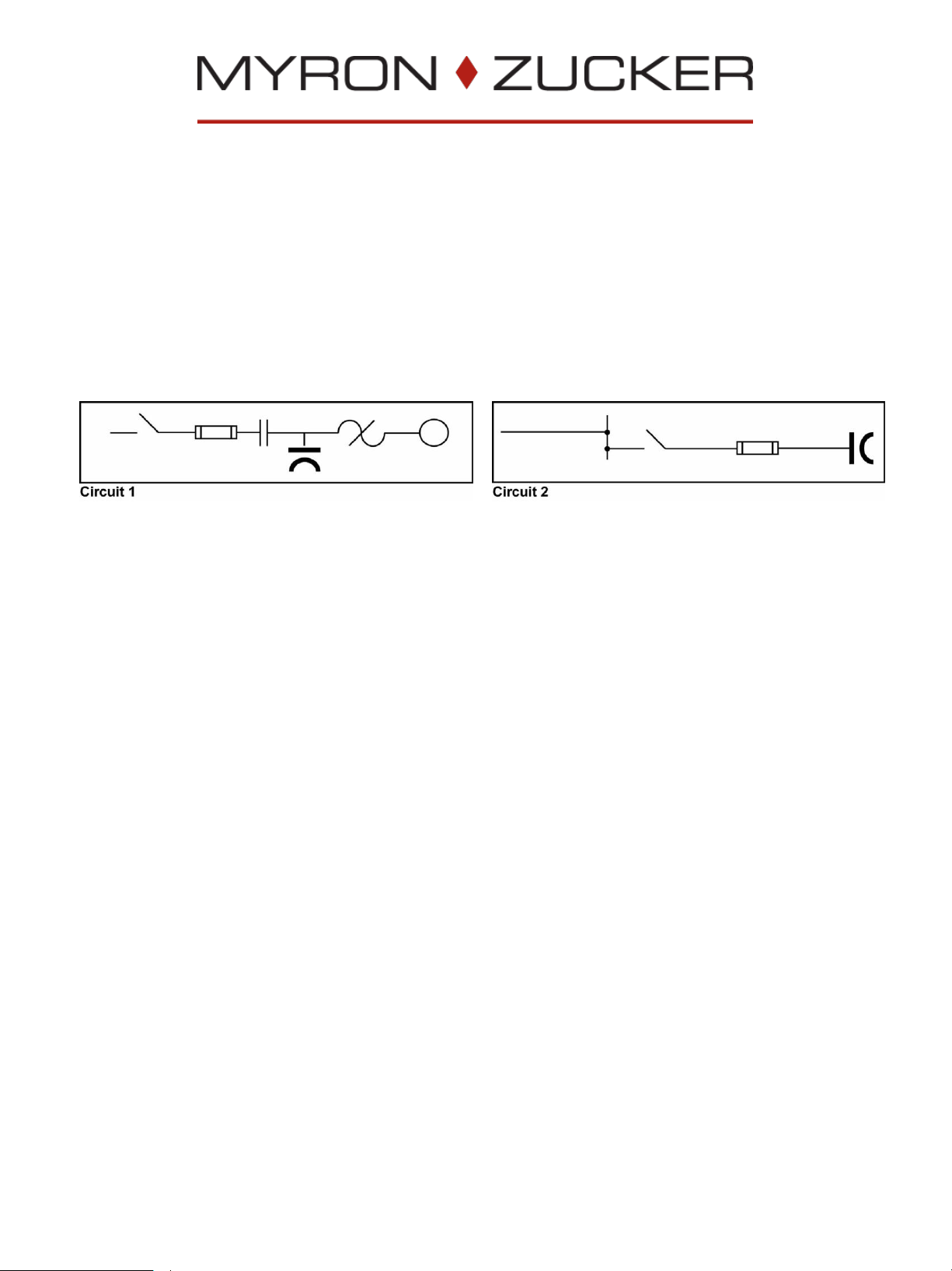
Calmount® brand capacitors can be connected either at the load (Circuit 1) or on the line (Circuit 2). In Circuit 2, the
capacitor must be connected through a disconnect device. Both circuits must have overcurrent protection. (For sizing, see
chart on back of these Installation Instructions.)
®
brand capacitor, please follow these Installation Instructions.
Capacitor lifetime is greatly reduced at high temperatures. Calmount® brand capacitors should be installed in cool
locations with good ventilation. Mechanical requirements of mounting the capacitor must also be considered. In general,
when selecting a mounting location:
• Avoid obvious “hot spots”, such as furnaces, transformers, heating ducts and direct sunlight.
• Avoid locations with harmonic voltages or currents.
• Allow at least three inches (3”) around the capacitor for air circulation.
• Allow mechanical clearances for:
- ducts and conduits (including future needs)
- construction
- machinery
- opening doors
- removal of the capacitor cover
• Position the capacitor for covenient nippling to cabinet or conduit and for visibility of indicator lights.
• Protect the capacitor from excessive dirt, dripping fluids and human interface.
LOCATION AMBIENT TEMPERATURE
Location ambient temperature is the temperature of the location before capacitors are installed, or with the capacitors
installed but not operating (not energized). This is the temperature of the surrounding air in the room, vault, substation or
enclosure where the capacitor will be operating. Maximum location ambient temperature should not exceed 46°C (115°F).
Page 2
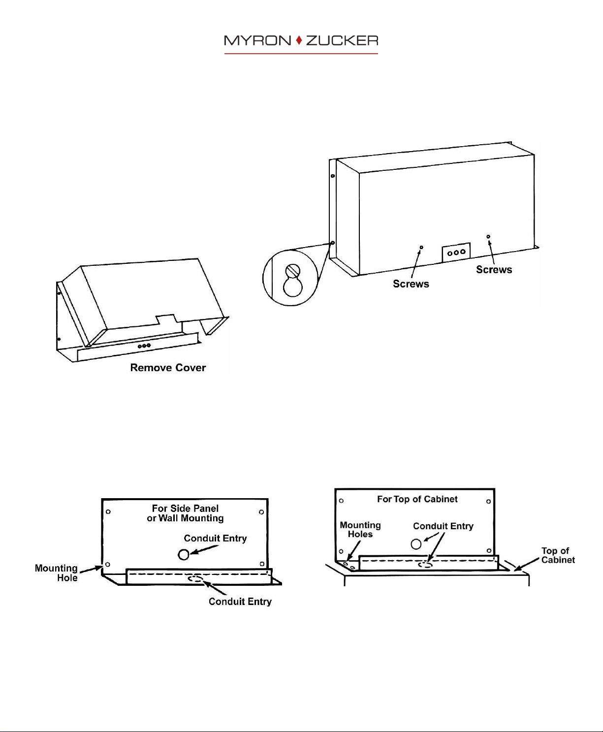
REMOVE COVER
The cover on all Calmount® brand capacitors is held on by four (4) side screws, and on larger units, two (2) or more front
panel screws.
To remove cover:
1. Take out front panel screws (if present).
2. Loosen side screws.
3. Lift cover off slightly.
4. Swing cover free from screws.
5. Lift cover off.
MOUNTING CALMOUNT® BRAND CAPACITORS
Place Calmount® brand capacitor on cabinet or wall, and mark mounting holes. (Mounting holes are prepunched on all
Calmount® brand capacitors.)
The following illustration shows the locations for conduit entry:
Page 3

Calmount® brand capacitors
Multical® brand capacitors
Electrical connections to these capacitors are made either to fuse
block, fuse lugs, or to a distribution block. Connect a single-phase
wire to each terminal. Be sure to attach grounding wire to
ground lug for safety.
On these units, each capacitor is wired to a
separate fuse block.
ATTACHING WIRES TO CALMOUNT
Select proper wire size from chart on back of these Installation Instructions.
CALMOUNT® BRAND CAPACITOR WITH CONTACTOR OPTION (CIRCUIT 3)
A two position terminal strip is provided for the remote operation of the contactor. Ensure that the voltage being supplied
to the contactor terminals is the same as the contactor coil.
INDICATING LIGHTS
Calmount® brand capacitor - KIM Series
On the KIM series capacitors, there are two (2) red lights and one (1) amber light. The two red lights are for indicating
blown fuses. The amber light serves two (2) indicating purposes:
blown fuse – middle phase (L2)
loss of capacitance in a capacitor cell detected by CelTel® brand indicator
Calmount® brand capacitor - KNM Series
On the KNM series capacitors, there are three (3) red indicating lights for indicating blown fuses. If a fuse blows, the fuse
light will illuminate. Each fuse light is wired in parallel to its fuse.
®
BRAND CAPACITORS
Page 4

KVAR
Current*
(Amps)
Wire Size
90° C-Type
THHN
XHHW* or
Equiv.†
Fuse
(Amps)
C.B. or
Switch
(Amps)
Current*
(Amps)
Wire Size
90° C-Type
THHN
XHHW* or
Equiv.†
Fuse
(Amps)
C.B. or
Switch
(Amps)
Current*
(Amps)
Wire Size
90° C-Type
THHN
XHHW* or
Equiv.†
Fuse
(Amps)
C.B. or
Switch
(Amps)
1 2.4 14 5 30 1.2 14 3 30 1.0 14 3 30
1.5 3.6 14 6 30 1.8 14 3 30 1.4 14 3 30
2 4.8 14 10 30 2.4 14 5 30 1.9 14 3 30
2.5 6.0 14 10 30 3.0 14 6 30 2.4 14 5 30
3 7.2 14 15 30 3.6 14 6 30 2.9 14 5 30
4 9.6 12 20 30 4.8 14 10 30 3.8 14 6 30
5 12 12 20 30 6.0 14 10 30 4.8 14 10 30
6 14 10 25 30 7.2 14 15 30 5.8 14 10 30
7.5 18 10 30 30 9.0 14 15 30 7.2 14 15 30
10 24 8 40 60 12 12 20 30 9.6 12 20 30
12.5 30 8 50 60 15 10 25 30 12 12 20 30
15 36 6 60 60 18 10 30 30 14 10 25 30
17.5 42 6 70 100 21 8 35 60 16 10 30 30
20 48 4 80 100 24 8 40 60 19 8 35 60
22.5 54 4 90 100 27 8 50 60 22 8 35 60
25 60 2 100 100 30 8 50 60 24 8 40 60
27.5 66 2 125 200 33 6 60 60 26 8 45 60
30 72 2 125 200 36 6 60 60 29 8 50 60
32.5 78 1/0 150 200 39 6 65 100 31 8 50 60
35 84 1/0 150 200 42 6 70 100 34 6 60 60
37.5 90 1/0 150 200 45 6 75 100 36 6 60 60
40 96 2/0 175 200 48 4 80 100 38 6 65 100
42.5 102 2/0 175 200 51 4 90 100 41 6 70 100
45 108 3/0 200 200 54 4 90 100 43 6 75 100
50 120 3/0 200 200 60 2 100 100 48 4 80 100
52.5 126 3/0 200 200 63 2 110 200 50 4 80 100
55 132 4/0 250 400 66 2 125 200 53 4 90 100
60 144 4/0 250 400 72 2 125 200 58 2 100 100
65 156 4/0 250 400 78 1/0 150 200 62 2 110 200
70 168 300MCM 300 400 84 1/0 150 200 67 2 125 200
75 180 300MCM 300 400 90 1/0 150 200 72 2 125 200
80 192 350MCM 350 400 96 2/0 175 200 77 1/0 150 200
90 216 500MCM 400 400 108 3/0 200 200 86 1/0 150 200
100 240 500MCM 400 400 120 3/0 200 200 96 2/0 175 200
125 300 (2)4/0 500 600 150 4/0 250 400 120 3/0 200 200
150 360 (2)300MCM 600 600 180 300MCM 300 400 144 4/0 250 400
175 420 (2)350MCM 700 800 210 500MCM 400 400 168 300MCM 300 400
200 480 (2)500MCM 800 800 240 500MCM 400 400 192 350MCM 350 400
225 540 (3)300MCM 900 1200 270 (2)4/0 500 600 216 500MCM 400 400
250 600 (3)350MCM 1000 1200 300 (2)4/0 500 600 240 500MCM 400 400
275 660 (3)500MCM 1100 1200 330 (2)300MCM 600 600 264 (2)4/0 500 600
300 720 (3)500MCM 1200 1200 360 (2)300MCM 600 600 288 (2)4/0 500 600
350 420 (2)350MCM 700 800 336 (2)300MCM 600 600
400 480 (2)500MCM 800 800 384 (2)350MCM 700 800
450 540 (3)300MCM 900 1200 432 (2)400MCM 750 800
500 600 (3)350MCM 1000 1200 480 (2)500MCM 800 800
550 660 (3)500MCM 1100 1200 528 (3)300MCM 900 1200
600 720 (3)500MCM 1200 1200 576 (3)350MCM 1000 1200
* Rated current based on operation at rated voltage, frequency, and KVAR
† Cons ul t National Electrical Code for other wire types . Above size base d on 35°C Ambient Operation. (Refer to NEC table 310-16.)
Note: Fuses furnished within Capacitor Assembly may be rated at higher value than shown in this table. The table is correct for field installations and
reflects the manufacturer's suggested rating for overcurrent protection and disconnect means in compliance with the National Electrical Code.
RECOMMENDED WIRE SIZES, SWITCHES, AND FUSES FOR 3-PHASE, 60Hz CAPACITORS
(These wire sizes are based on 135% of rated current in accordance with the National Electrical Code, Article 460.)
240 VOLTS
480 VOLTS
600 VOLTS
USE COPPER CONDUCTORS ONLY. UNIT TERMINALS ARE NOT DESIGNED TO ACCEPT OTHER TYPE
WIRING. THE USE OF ALUMINUM WIRING MAY CAUSE GALVANIC CORROSION AND/OR OVERHEATING AT
CAUTION:
 Loading...