

Page 1

™
TECHPRO
Operation
Manual
MODELS TPH1, TP1 & TH1
12 Apr 07 DFT 9
Page 2

TechPro
TPH1
BUFFER
°C °F
TDS
pH
COND
10 jan 06
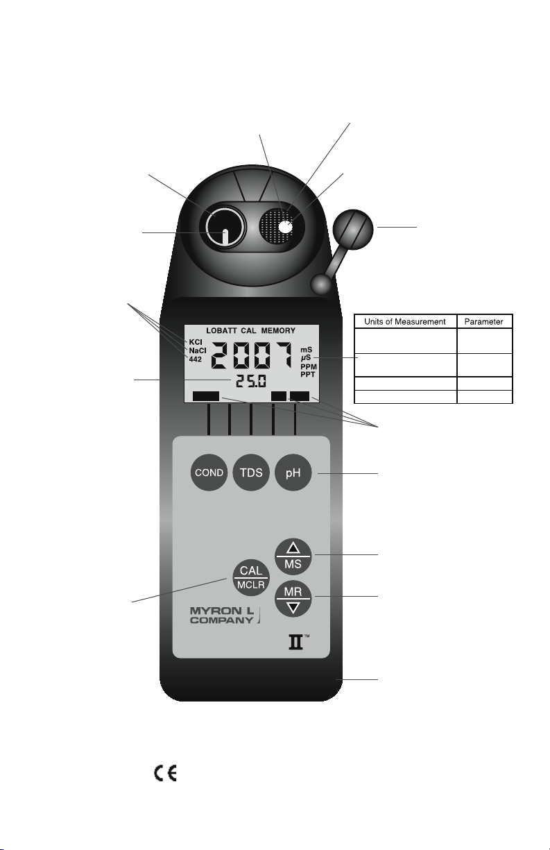
Wrist/neck strap slot
(strap user supplied)
pH Sensor
Protective Cap
Up key/Memory Store
Down key/Memory Recall
Displayed here:
• Temperature
readout
• Memory Storage
Location
• pH Calibration
This Key for:
• Calibration
• Memory Clear
• Solution Selection
• Confirmation
These Measurement Keys will:
• Turn instrument on
• Measure parameter
• Exit any function
Icons for pH, Conductivity or
Total Dissolved Solids (TDS)
pH Glass
Electrode
pH Sensor
(User replaceable)
Reference
Junction
(under Glass
Bulb)
Conductivity Cell
(Built-in
Electrodes)
Temperature
Sensor
Preprogrammed
conductivity/
TDS ratios
For detailed explanations, see Table of Contents
Instrument Illustration
MODEL TPH1 Shown
TDS/SalinityPPT - parts per thousand
µS - microsiemens/cm
(micromhos/cm)
mS - millisiemens/cm
(millimhos/cm)
PPM - parts per million TDS
Conductivity
Conductivity/
Salinity
Page 3
TechPro
TPH1
BUFFER
°C °F
TDS
pH
COND
10 jan 06
Wrist/neck strap slot
(strap user supplied)
pH Sensor
Protective Cap
Up key/Memory Store
Down key/Memory Recall
Displayed here:
• Temperature
readout
• Memory Storage
Location
• pH Calibration
This Key for:
• Calibration
• Memory Clear
• Solution Selection
• Confirmation
These Measurement Keys will:
• Turn instrument on
• Measure parameter
• Exit any function
Icons for pH, Conductivity or
Total Dissolved Solids (TDS)
pH Glass
Electrode
pH Sensor
(User replaceable)
Reference
Junction
(under Glass
Bulb)
Conductivity Cell
(Built-in
Electrodes)
Temperature
Sensor
Preprogrammed
conductivity/
TDS ratios
For detailed explanations, see Table of Contents
Instrument Illustration
MODEL TPH1 Shown
TDS/SalinityPPT - parts per thousand
µS - microsiemens/cm
(micromhos/cm)
mS - millisiemens/cm
(millimhos/cm)
PPM - parts per million TDS
Conductivity
Conductivity/
Salinity
i
Page 4

ii
Page 5

I. INTRODUCTION
Thank you for selecting the feature-packed TechPro II™, one of the
Myron L Company’s latest in an increasing line of instruments utilizing
advanced microprocessor-based circuitry and SMT manufacturing
processes. This circuitry makes the instrument extremely accurate,
reliable and very easy to use.
The TechPro II incorporates several new features including: waterproof
enclosure, keypad calibration, FULL 4 digit LCD, the addition of a 20
location memory storage, and enhanced performance to name just some
of the improvements. Additionally, “salinity” units may be selected. See
Features and Specications on pages 2 & 3.
For your convenience, on the bottom side of your TechPro II is a brief
set of instructions.
Special note ... For the TPH1 & TP1 models, conductivity and TDS
require mathematical correction to 25°C values (ref. Temperature
Compensation, pg. 27). On the left of the TechPro II’s liquid crystal
display is shown an indicator of the salt solution characteristic used to
model temperature compensation (Tempco) of conductivity and its TDS
conversion. The indicator may be KCl, NaCl, or 442™. Selection affects
the temperature correction of conductivity, and the calculation of TDS
from compensated conductivity (ref. Conductivity Conversion to Total
Dissolved Solids (TDS), pg. 30).
The selection can affect the reported conductivity of hot or cold solutions,
and will change the reported TDS of a solution. Generally, using KCl
for conductivity, and 442 (Natural Water characteristic) for TDS will
reect present industry practice for standardization. This is how your
instrument, as shipped from the factory, is set to operate. For use in sea
water desalination for example, both the CONDuctivity and TDS may
easily be changed to NaCl.
1
Page 6

II. FEATURES and SPECIFICATIONS
A. Features
• Ranges:
Conductivity/TDS — 0- 20,000 µS/ppm (TPH1 & TP1)
pH — 0 -14 (TPH1 & TH1)
• Superior resolution four (4) digit LCD.
• Conductivity/TDS accuracy of ±1% of reading
• pH accuracy of ±.01 pH units (TPH1 & TH1)
• All electrodes are internal for maximum protection
• Waterproof to 1 meter/3 feet
• Memory storage (20 readings)
• Autoranging Conductivity/TDS (TPH1 & TP1)
• Easy keypad calibration
• Prompts for simple pH calibration (TPH1 & TH1).
• Factory calibrations stored in microprocessor
• User selectable Conductivity/TDS modes (TPH1 & TP1)
• 3 “User Selectable” solution conversions (tempcos) (TPH1 & TP1)
• User Selectable “Salinity” units (TPH1 & TP1)
• Temperature accuracy of ±0.1°C/F
• Automatic Temperature Compensation to 25°C
• Temperature Compensation disable feature
B. General Specications
Display 4 Digit LCD
Dimensions (Lx W x H) 196 x 68 x 64 mm
7.7 x 2.7 x 2.5 in.
Weight 320 g/11.2 oz.
Case Material ABS
Cond/ TDS Cell Material ABS
Cond/ TDS Electrodes 316 Stainless Steel
Cond/ TDS Cell Capacity 5 ml/ 0.2 oz.
pH Sensor Well Capacity 1,2 ml/ 0.04 oz. (TPH1 & TH1)
Power 9V Alkaline Battery
Battery Life >100 Hours/ 5000 Readings
Operating/ Storage Temperature 0-55°C/ 32-132°F
Protection Ratings IP67/NEMA 6
(waterproof to 1 meter/3 feet)
Additional information is available on our website at:
www.myronl.com
2
Page 7

C. Specication Chart
pH
(TPH1
& TH1)
Ranges 0-14 pH 0-9999 µS/cm
Resolution
Accuracy ±.01 pH ±1% of reading ±0.1°C/F
Auto Temperature
Compensation
Conductivity or
TDS Ratios
.01 pH 0.1 (<1000 µS)
0-71°C
32-
160°F
Conductivity TDS Temperature
10-20 mS/cm in
3 autoranges
1.0 (<10 mS)
0.01 (>10 mS)
0-71°C
32-160°F
KCl, NaCl, or 442™
0-9999 ppm
10-20 ppt in 3
autoranges
0.1 (<1000 ppm)
1.0 (<10 ppt)
0.01 (>10 ppt)
0-71°C
32-160°F
0.1°C/F
D. Warranty/Service
The Myron L TechPro II™, excluding the pH sensor (TPH1 & TH1), has
a Two (2) Year Limited Warranty. The pH sensor (TPH1 & TH1) has a
Six (6) Month Limited Warranty. If an instrument fails to operate properly,
see Troubleshooting Chart, pg. 24. The battery and pH sensor (TPH1)
are user-replaceable. For other service, return the instrument prepaid to
the Myron L Company.
MYRON L COMPANY
2450 Impala Drive
Carlsbad, CA 92010-7226 USA
760-438-2021
www.myronl.com
If, in the opinion of the factory, failure was due to materials or workmanship,
repair or replacement will be made without charge. A reasonable service
charge will be made for diagnosis or repairs due to normal wear, abuse
or tampering. This warranty is limited to the repair or replacement of the
TechPro II only. The Myron L Company assumes no other responsibility
or liability.
E. TechPro II™ Series Models
TechPro II Models
Parameters pH & Conductivity, Conductivity,
TH1 TP1 TPH1
Temperature TDS & TDS, pH &
Temperature Temperature
MADE IN USA
3
Page 8

TABLE OF CONTENTS
Instrument Illustration . . . . . . . . . . . . . . . . . . . . . . . . . . . . . . . . . . . . . . i
I. INTRODUCTION . . . . . . . . . . . . . . . . . . . . . . . . . . . . . . . . . . . 1
II. FEATURES and SPECIFICATIONS . . . . . . . . . . . . . . . . . . . . 2
A. Features . . . . . . . . . . . . . . . . . . . . . . . . . . . . . . . . 2
B. General Specications . . . . . . . . . . . . . . . . . . . . . 2
C. Specication Chart . . . . . . . . . . . . . . . . . . . . . . . . 3
D. Warranty/Service . . . . . . . . . . . . . . . . . . . . . . . . . 3
E. TechPro II Series Models . . . . . . . . . . . . . . . . . . . 3
III. RULES of OPERATION. . . . . . . . . . . . . . . . . . . . . . . . . . . . . . 6
A. Operation . . . . . . . . . . . . . . . . . . . . . . . . . . . . . . . 6
B. Characteristics of the Keys . . . . . . . . . . . . . . . . . . 6
C. Operation of the Keys . . . . . . . . . . . . . . . . . . . . . . 6
1. Measurement Keys in General . . . . . . . . . 6
2. COND and TDS Keys (TPH1 & TP1) . . . . 6
3. pH Key (TPH1 & TH1) . . . . . . . . . . . . . . . 7
4. CAL/MCLR Key . . . . . . . . . . . . . . . . . . . . 7
5. UP or DOWN Keys . . . . . . . . . . . . . . . . . . 7
IV. AFTER USING the TechPro II . . . . . . . . . . . . . . . . . . . . . . . . 8
A. Maintenance of the Conductivity Cell
(TPH1 & TP1) . . . . . . . . . . . . . . . . . . . . . . . . . . . . . . . 8
B. Maintenance of the pH Sensor (TPH1 & TH1) . . . 8
V. SPECIFIC RECOMMENDED MEASURING PROCEDURES . . 8
A. Measuring Conductivity/ Total Dissolved Solids . . 8
B. Measuring pH (TPH1 & TH1) . . . . . . . . . . . . . . . . 8
VI. SOLUTION SELECTION (TPH1 & TP1) . . . . . . . . . . . . . . . . . 9
A. Why Solution Selection is Available . . . . . . . . . . . 9
B. The 3 Solution Types. . . . . . . . . . . . . . . . . . . . . . . 9
C. Calibration of Each Solution Type. . . . . . . . . . . . . 9
D. Procedure to Select a Solution . . . . . . . . . . . . . . . 9
VII. CALIBRATION . . . . . . . . . . . . . . . . . . . . . . . . . . . . . . . . . . . 10
A. Calibration Intervals . . . . . . . . . . . . . . . . . . . . . . 10
B. Rules for Calibration of the TechPro II . . . . . . . . 10
1. Calibration Steps . . . . . . . . . . . . . . . . . . 10
2. Calibration Limits . . . . . . . . . . . . . . . . . . 11
C. Calibration Procedures
1. Conductivity or TDS Calibration
(TPH1 & TP1) . . . . . . . . . . . . . . . . . . . . . 11
2. Reloading Factory Calibration . . . . . . . . 12
3. pH Calibration (TPH1 & TH1) . . . . . . . . . 12
VIII. CALIBRATION INTERVALS . . . . . . . . . . . . . . . . . . . . . . . . . 15
A. Suggested Intervals . . . . . . . . . . . . . . . . . . . . . . 15
B. Calibration Tracking Records . . . . . . . . . . . . . . . 15
C. Conductivity or TDS Practices (TPH1 & TP1). . . 15
D. pH Practices (TPH1 & TH1) . . . . . . . . . . . . . . . . 16
4
Page 9

IX. MEMORY. . . . . . . . . . . . . . . . . . . . . . . . . . . . . . . . . . . . . . . . 16
A. Memory Storage . . . . . . . . . . . . . . . . . . . . . . . . . 16
B. Memory Recall . . . . . . . . . . . . . . . . . . . . . . . . . . 16
C. Clearing a Record/Memory Clear . . . . . . . . . . . . 17
X. TEMPERATURE FORMAT “Centigrade & Fahrenheit” . . . . . 18
XI. TEMPERATURE COMPENSATION (TC) DISABLE
(TPH1 & TP1) . . . . . . . . . . . . . . . . . . . . . . . . . . . . . . . . . . . 18
XII. SALINITY UNITS (TPH1 & TP1) . . . . . . . . . . . . . . . . . . . . . . 19
XIII. TOTAL RETURN to FACTORY SETTINGS. . . . . . . . . . . . . . 20
XIV. CARE and MAINTENANCE . . . . . . . . . . . . . . . . . . . . . . . . . 20
A. Temperature Extremes . . . . . . . . . . . . . . . . . . . . 20
B. Battery Replacement (LO BATT) . . . . . . . . . . . . 21
C. pH Sensor Replacement (TPH1 & TH1) . . . . . . . 21
D. Cleaning Sensors . . . . . . . . . . . . . . . . . . . . . . . . 21
XV. TROUBLESHOOTING CHART . . . . . . . . . . . . . . . . . . . . . . . 24
XVI. ACCESSORIES. . . . . . . . . . . . . . . . . . . . . . . . . . . . . . . . . . . 26
A. Conductivity/TDS Standard Solutions
(TPH1 & TP1) . . . . . . . . . . . . . . . . . . . . . . . . . . . 26
B. pH Buffer Solutions (TPH1 & TH1) . . . . . . . . . . . 26
C. pH Sensor Storage Solution (TPH1 & TH1) . . . . 26
D. Soft Protective Case . . . . . . . . . . . . . . . . . . . . . . 27
E. Hard Protective Carry Cases . . . . . . . . . . . . . . . 27
F. Replacement pH Sensor (TPH1 & TH1) . . . . . . . 27
XVII. TEMPERATURE COMPENSATION (TPH1 & TP1) . . . . . . . 27
A. Standardized to 25°C . . . . . . . . . . . . . . . . . . . . . 27
B. Tempco Variation. . . . . . . . . . . . . . . . . . . . . . . . . 27
C. An Example. . . . . . . . . . . . . . . . . . . . . . . . . . . . . 28
D. A Chart of Comparative Error . . . . . . . . . . . . . . . 28
E. Other Solutions . . . . . . . . . . . . . . . . . . . . . . . . . . 29
XVIII. CONDUCTIVITY CONVERSION to
TOTAL DISSOLVED SOLIDS (TDS) (TPH1 & TP1). 30
A. How it’s Done . . . . . . . . . . . . . . . . . . . . . . . . . . . 30
B. Solution Characteristics . . . . . . . . . . . . . . . . . . . 30
C. When does it make a lot of difference?. . . . . . . . 30
XIX. TEMPERATURE COMPENSATION (Tempco)
and TDS DERIVATION (TPH1 & TP1) . . . . . . . . . . . 31
XX. pH MEASUREMENT (TPH1 & TH1) . . . . . . . . . . . . . . . . . . . 31
A. pH as an Indicator (TPH1 & TH1) . . . . . . . . . . . . 31
B. pH Units (TPH1 &TH1) . . . . . . . . . . . . . . . . . . . . 32
C. pH Sensor (TPH1 &TH1) . . . . . . . . . . . . . . . . . . 32
D. Myron L Integral pH Sensor (TPH1 &TH1) . . . . . 33
E. Sources of Error (TPH1 &TH1) . . . . . . . . . . . . . . 33
XXI. SOFTWARE VERSION . . . . . . . . . . . . . . . . . . . . . . . . . . . . . 34
XXII. GLOSSARY. . . . . . . . . . . . . . . . . . . . . . . . . . . . . . . . . . . . . . 35
XXIII. ADDENDUM . . . . . . . . . . . . . . . . . . . . . . . . . . . . . . . . . . . . . 36
XXIV. NOTES . . . . . . . . . . . . . . . . . . . . . . . . . . . . . . . . . . . . . . . . . 38
5
Page 10

III. RULES of OPERATION
A. Operation
Using the instrument is simple:
• Individual or multiple parameter readings may be obtained by
lling individual sensors or entire cell cup area.
• Rinse the conductivity cell or pH sensor well (TPH1 &TH1) with
test solution 3 times and rell. Temperature and/or
measurement extremes will require additional rinses for
maximum accuracy.
• Press the desired measurement key to start measurement.
Pressing the key again restarts the 20 second auto “off” timer.
• Note the value displayed or press the MS key to store the
reading (ref. Memory Storage, pg. 16). It’s that simple!
B. Characteristics of the Keys
• Though your TechPro II has a variety of sophisticated options,
it is designed to provide quick, easy, accurate measurements
by simply pressing one key.
• All functions are performed one key at a time.
• There is no “off” key. After 20 seconds of inactivity the
instrument turns itself off (60 seconds in CAL mode).
• Rarely is it necessary to press and
to Select a Solution, pg. 9; or Cond. or TDS Calibration, pg. 11).
C. Operation of the Keys (See Instrument Illustration on pg. i)
1. Measurement Keys in General
The measurement keys turn on the instrument in the mode selected.
The parameter is shown at the bottom of the display, and the measurement
units appear at the right. Pressing a measurement key does this even
if you are in a calibration sequence and also serves to cancel a change
(ref. Leaving Calibration, pg. 11).
hold
a key (as in Procedure
2. COND and TDS Keys (TPH1 & TP1)
These keys are used with solution in the Conductivity Cell.
Precautions:
• While lling cell cup ensure no air bubbles cling on the cell wall.
• If the proper solution is not selected (KCl, NaCl or 442), (ref.
Why Solution Selection is Available, pg. 9).
a. COND Key
Solution to be tested is introduced into the conductivity cell and a press
of displays conductivity with units on the right. On the left is
shown the solution type selected for conductivity.
6
Page 11
b. TDS Key
A press of displays Total Dissolved Solids with units on the right.
This is a display of the concentration of material calculated from
compensated conductivity using the characteristics of a known material.
On the left is shown solution type selected for TDS (ref. Solution
Selection, pg. 9).
3. pH Key (TPH1 & TH1)
Measurements are made on the solution contained in the pH sensor
well (ref. pH Measurement, pg. 31). The protective cap is removed,
and the sensor well is lled and rinsed with the sample enough times to
completely replace the pH Sensor Storage Solution.
After use, the pH sensor well must be relled with Myron L pH Sensor
Storage Solution, and the protective cap reinstalled securely (ref.
Maintenance of the pH Sensor, pg. 8 and pH, pg. 21).
A press of displays pH readings. No units are displayed.
4. CAL/MCLR Key
A press of allows you to enter the calibration mode while
measuring conductivity, TDS or pH. Once in CAL mode, a press of this
key accepts the new value. If no more calibration options follow, the
instrument returns to measuring (ref. Leaving Calibration, pg. 11).
If is held down for 3 seconds, CAL mode is not entered, but
“SEL” appears to allow Solution Selection (ref. pg. 9) with the Up or
Down keys. As in calibration, the CAL key becomes an “accept” key.
While reviewing stored records, the MCLR side of the key is active to
allow clearing records (ref. Clearing a Record/Memory Clear, pg. 17).
5. UP or DOWN Keys
While measuring in any parameter, the or keys activate
the Memory Store and Memory Recall functions.
While in CAL mode, the keys step or scroll the displayed value up or
down. A single press steps the display and holding either key scrolls the
value rapidly.
While in Memory Recall, these keys scroll the display up and down
through the stack of records (ref. Memory Recall, pg. 16).
7
Page 12

IV. AFTER USING the TechPro II
A. Maintenance of the Conductivity Cell (TPH1& TP1)
Rinse out the cell cup with clean water. Do not scrub the cell. For oily lms,
squirt in a foaming non-abrasive cleaner and rinse. (ref. Conductivity or
TDS, pg. 21). Even if a very active chemical discolors the electrodes, this
does not affect the accuracy; leave it alone.
B. Maintenance of the pH Sensor (TPH1 & TH1)
The sensor well must be kept wet with a solution. Before replacing the
rubber cap, rinse and ll the sensor well with Myron L pH Sensor Storage
Solution. If unavailable, use an almost saturated KCl solution, pH 4 buffer
(ref. pH Buffer Solutions, pg. 26) or a saturated solution of table salt and
tap water. NEVER USE DISTILLED WATER (ref. pH, pg. 21).
V. SPECIFIC RECOMMENDED MEASURING
PROCEDURES
Verify proper solution setting (KCl, NaCl, or 442), (ref. Solution Selection,
pg. 9).
NOTE: After sampling high concentration solutions or temperature
extremes, more rinsing may be required. When sampling low conductivity
solutions, be sure the pH cap is well seated so that no solution washes
into the conductivity cell from around the pH cap.
A. Measuring Conductivity & Total Dissolved Solids (TDS)
1. Rinse cell cup 3 times with sample to be measured. (This
conditions the temperature compensation network and
prepares the cell.)
2. Rell cell cup with sample.
3. Press or .
4. Note value displayed.
B. Measuring pH (TPH1 & TH1)
1. Remove protective cap by squeezing its at sides and pulling up.
2. Rinse sensor well 3 times with sample to be measured. Shake
out each sample to remove any residual liquid.
3. Rell both sensor wells with sample.
8
Page 13

4. Press .
5. Note value displayed.
6. IMPORTANT: After use, ll pH sensor well with Myron L
pH Sensor Storage Solution and replace protective cap.
If Myron L pH Sensor Storage Solution is unavailable, use a
strong KCl solution, a pH 4 buffer, or a saturated solution of
table salt and tap water (ref. Cleaning Sensors, 2. pH, pg. 21).
VI. SOLUTION SELECTION (TPH1 & TP1)
A. Why Solution Selection is Available
Conductivity and TDS require temperature correction to 25°C values (ref.
Standardized to 25°C, pg. 27). Selection determines the temperature
correction of conductivity and calculation of TDS from compensated
conductivity (ref. Cond. Conversion to TDS, pg. 30).
B. The 3 Solution Types
On the left side of the display is the salt solution characteristic used
to model temperature compensation of conductivity and its TDS
conversion. Generally, using KCl for conductivity, and 442 (Natural
Water characteristic) for TDS will reect present industry practice for
standardization. This is how your instrument is shipped from the factory
(ref. Solution Characteristics, pg. 30). NaCl may be user selected for
either.
Do not allow pH sensor to dry out.
C. Calibration of Each Solution Type
There is a separate calibration for each of the 3 solution types. Note
that calibration of a 442 solution does not affect the calibration of a NaCl
solution. For example: Calibration (ref. Conductivity or TDS Calibration,
pg. 11) is performed separately for each type of solution one wishes to
measure (ref. Conductivity/TDS Standard Solutions, pg. 26).
D. Procedure to Select a Solution
NOTE: Check display to see if solution displayed (KCl, NaCl or 442) is
already the type desired. If not:
1. Press or to select the parameter on which
you wish to change the solution type.
9
Page 14
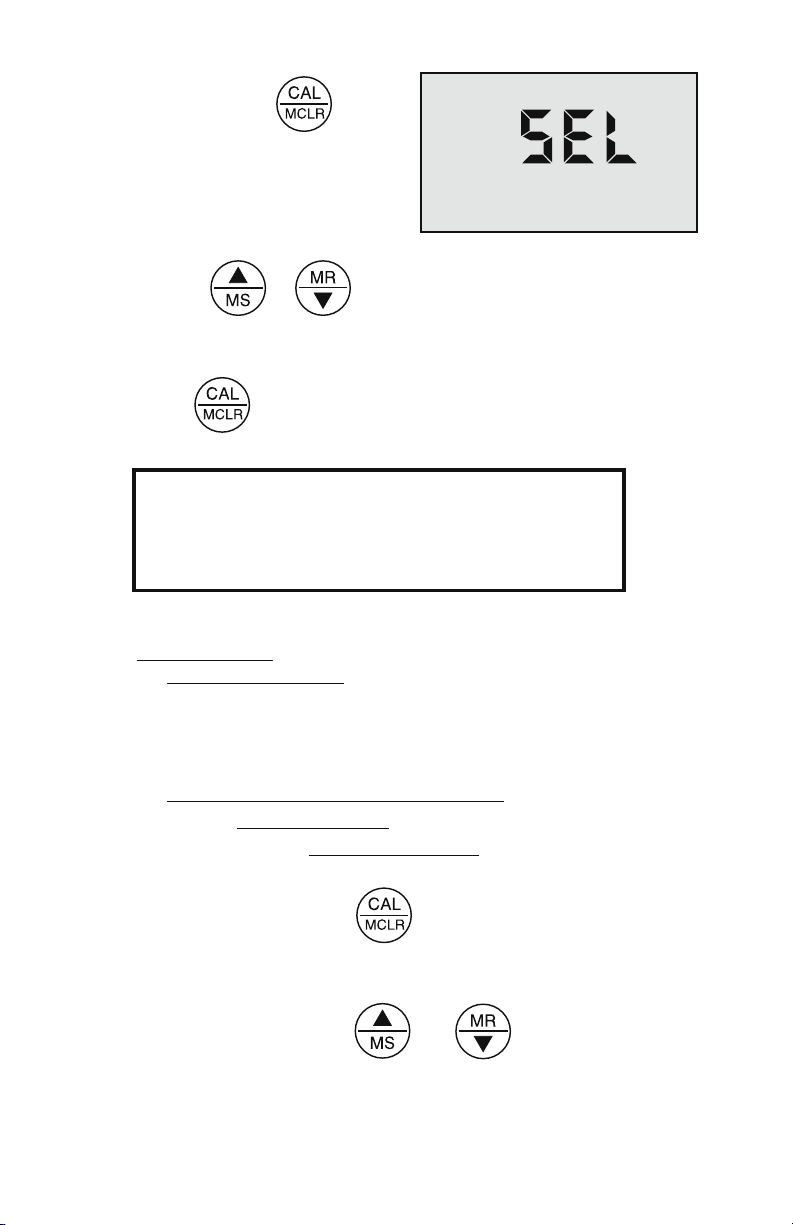
2. Press and hold key
Figure 1
KCl
442
NaCl
In the first six sections, you have learned all
you need to take accurate measurements.
The following sections contain calibration,
advanced operations and technical information.
for 3 seconds. “SEL” will be
displayed (see Figure 1).
For demonstration purposes,
all 3 solution types are
shown simultaneously.
3. Use the or key to select type of solution desired
(ref. Solution Characteristics, pg. 30). The selected solution
type will be displayed: KCl, NaCl or 442.
4. Press to accept new solution type.
VII. CALIBRATION
A. Calibration Intervals
Generally, calibration is recommended about once per month with
Conductivity or TDS solutions. Calibration with pH solutions should be
checked twice a month. (ref. CALIBRATION INTERVALS, pg. 15).
B. Rules for Calibration of the TechPro II
1. Calibration Steps
a. Starting Calibration
Calibration is begun by pressing while measuring Conductivity,
TDS or pH. Measuring continues, but the CAL icon is on, indicating
calibration is now changeable.
The reading is changed with the and keys to match the
10
Page 15

known value. The calibration for each of the 3 solution types may be
performed in either conductivity or TDS mode.
Depending on what is being calibrated, there may be 1, 2 or 3 steps to
the calibration procedures.
Once in “CAL” mode, the key becomes an “ACCEPT” key. At
each point, pressing accepts the new calibration value and steps
you to the next adjustment (or out of CAL mode if there are no more
steps).
To bypass a calibration step, simply press to accept the present
value as is.
b. Leaving Calibration
Calibration is complete when the “CAL” icon goes out. Pressing any
measurement key cancels changes not yet accepted and exits calibration
mode.
Leaving pH after the 2nd buffer results in the same gain being entered in
place of the 3rd buffer.
2. Calibration Limits
There are calibration limits. A nominal “FAC” value is an ideal value
stored by the factory. Attempts to calibrate too far, up or down, from there
will cause the displayed value to be replaced with “FAC”. If you accept it
(press the “Cal” key) you will have the original default factory calibration
for this measurement. The need to calibrate so far out that “FAC” appears
indicates a procedural problem, incorrect standard solution, a very dirty
cell cup or an aging pH sensor (ref. Troubleshooting Chart, pg. 24).
C. Calibration Procedures
1. Conductivity or TDS Calibration (TPH1 & TP1)
a. Rinse conductivity cell three times with proper standard (KCl,
NaCl, or 442) (ref. Cond/TDS Standard Solutions, pg. 26).
b. Rell conductivity cell with same standard. KCl-7000 used in
Figure 2, pg. 12.
c. Press or , then press , “CAL” icon will
11
Page 16

appear on the display
Figure 2
°C
KCl
COND
CAL
(see Figure 2).
d. Press or to step
the displayed value toward the
standard’s value (7032 >7000)
or hold a key down to scroll rapidly through the reading.
e. Press once to conrm new value and end the calibration
sequence for this particular solution type. If another solution
type is also to be measured, change solution type now and
repeat this procedure.
2. Reloading Factory Calibration (Cond or TDS)
If calibration is suspect or known to be incorrect, and no standard solution
is available, the calibration value can be replaced with the original factory
value for that solution. This “FAC” value is the same for all TechPro IIs,
and returns you to a known state without solution in the cell. The “FAC”
internal electronics calibration (which bypasses the electrodes and cell) is
not intended to replace calibration with conductivity standard solutions. If
another solution type requires resetting, change solution type and repeat
this procedure.
a. Press or .
b. Press .
c. Press key until “FAC” appears and release.
d. Press to accept the factory calibration setting.
3. pH Calibration (TPH1 & TH1)
Important: Always “zero” your TechPro II with a pH 7 buffer solution
before adjusting the gain with acid or base buffers, i.e., 4 and/or 10.
12
Page 17

a. pH Zero Calibration (TPH1 & TH1)
Figure 3
BUFFER
pH
CAL
1. Rinse sensor well 3 times with 7 buffer solution.
2. Rell both sensor wells with 7 buffer solution.
3. Press to verify the pH
calibration. If the display
shows 7.00, skip the pH Zero
Calibration and proceed to
section b. pH Gain Calibration.
4. Press to enter calibration mode. The “CAL”, “BUFFER”
and “7” annunciators will appear (see Figure 3). Displayed
value will be the uncalibrated sensor.
NOTES: If a wrong buffer is added (outside of 6-8 pH), “7” and “BUFFER”
will ash, and the TechPro II will not adjust.
The uncalibrated pH value displayed in step 4 will assist in determining
the accuracy of the pH sensor. If the pH reading is above 8 with pH 7
buffer solution, the sensor well needs additional rinsing or the pH sensor
is defective and needs to be replaced
.
5. Press or until the display reads 7.00.
NOTE: Attempted calibration of >1 pH point from factory calibration will
cause “FAC” to appear. This indicates the need for sensor replacement
(ref. Troubleshooting pg. 24) or fresh buffer solution. The “FAC” internal
electronic calibration is not intended to replace calibration with pH buffers.
It assumes an ideal pH sensor. Each “FAC” indicates a factory setting for
that calibration step (i.e., 7, acid, base).
You may press to accept the preset factory value, or you may
reduce your variation from factory setting by pressing or .
6. Press to accept the new value. The pH Zero Calibration
is now complete. You may continue with pH Gain Calibration or
exit by pressing any measurement key.
13
Page 18

b. pH Gain Calibration (TPH1 & TH1)
Figure 4
BUFFER
pH
CAL
Figure 5
pH
BUFFER
CAL
Important: Always calibrate or verify your TechPro II with a pH 7 buffer
solution before adjusting the gain with acid or base buffers, i.e., 4 and/or
10, etc. Either acid or base solution can be used for the 2nd point “Gain”
calibration and then the opposite for the 3rd point. The display will verify
that a buffer is in the sensor well by displaying either “Acd” or “bAS”.
1. The pH calibration mode is initiated by either completion of the
pH Zero Calibration, or verifying 7 buffer and pressing the
key twice while in pH measurement mode.
2. At this point the “CAL”, “BUFFER” and “Acd” or “bAS”
annunciators will be displayed (see Figures 4 and 5).
NOTE: If the “Acd” and “bAS” indicators are blinking, the unit is indicating
an error and needs either an acid or base solution present in the sensor
well
.
3. Rinse sensor well 3 times with acid or base buffer solution.
4. Rell sensor well again with same buffer solution.
5. Press or until display agrees with buffer value.
6. Press to accept 2nd point of calibration. Now the display
indicates the next type of buffer to be used.
Single point Gain Calibration is complete. You may continue for the 3rd
point of Calibration (2nd Gain) or exit by pressing any measurement key.
Exiting causes the value accepted for the buffer to be used for both acid
and base measurements.
To continue with 3rd point calibration, use base buffer if acid buffer was
used in the 2nd point, or vice-versa. Again, match the display to the
14
Page 19

known buffer value as in step 2 and continue with the following steps:
7. Repeat steps 3 through 5 using opposite buffer solution.
8. Press to accept 3rd point of calibration, which completes
the Calibration procedure. Fill sensor well with Myron L pH
Sensor Storage Solution and replace protective cap.
VIII. CALIBRATION INTERVALS
There is no simple answer as to how often one should calibrate
an instrument. The TechPro II is designed to not require frequent
recalibration. The most common sources of error were eliminated in
the design, and there are no mechanical adjustments. Still, to ensure
specied accuracy, any instrument must be checked against chemical
standards occasionally.
A. Suggested Intervals
On the average, we expect calibration need only be checked monthly
for the Conductivity or TDS functions. The pH (TPH1 & TH1) function
should be checked every 2 weeks to ensure accuracy. Measuring some
solutions will require more frequent intervals.
B. Calibration Tracking Records
To minimize your calibration effort, keep records. If adjustments you
are making are minimal for your application, you can check less often.
Changes in conductivity calibration should be recorded in percent.
Changes in pH calibration (TPH1 & TH1) are best recorded in pH units.
Calibration is purposely limited in the TechPro II to ±10% for the
conductivity cell, as any change beyond that indicates damage, not drift.
Likewise, calibration changes are limited to ±1 pH unit (TPH1 & TH1),
as any change beyond that indicates the end of the sensor’s lifetime and
replacement is recommended.
C. Conductivity, RES, TDS Practices to Maintain Calibration
1. Clean oily lms or organic material from the cell electrodes with
foaming cleaner or mild acid. Do not scrub inside the cell.
2. Calibrate with solutions close to the measurements you make.
Readings are compensated for temperature based on the
type of solution. If you choose to measure tap water with a
15
Page 20

KCl compensation, which is often done (ref. Temperature
Figure 6
°C
KCl
COND
MEMORY
Compensation, pg. 27), and you calibrate with 442 solution
because it is handy, the further away from 25°C you are, the
more error you have. Your records of calibration changes
will reect temperature changes more than the instrument’s
accuracy.
3. Rinse out the cell with pure water after taking measurements.
Allowing slow dissolving crystals to form in the cell contaminates
future samples.
4. For maximum accuracy, keep the pH sensor cap on tight so
that no uid washes into the conductivity cell.
D. pH Practices to Maintain Calibration (TPH1 & TH1)
1. Keep the sensor wet with Myron L pH Sensor Storage Solution.
2. Rinse away caustic solutions immediately after use.
IX. MEMORY
This feature allows up to 20 readings with their temperatures to be stored
simultaneously for later recall.
A. Memory Storage
1. While displaying a measurement, press to record the
displayed value.
2. “MEMORY” will appear and
the temperature display will be
momentarily replaced by a
number (1-20) showing the
position of the record. Figure
6 shows a reading of 1806 µS
stored in memory record #4.
B. Memory Recall
1. Press any measurement key.
2. Press , “MEMORY” will appear, and the display will show
16
Page 21

the last record stored.
Figure 7
MEMORY
3. Press or to scroll to the record location desired
(the temperature display alternates between temperature
recorded and location number).
4. Press any measurement key to leave memory recall or allow to
automatically turn off.
C. Clearing a Record/Memory Clear
After recalling a certain record location, press to clear that
memory. This space will be the place for the next memory record, unless
you scroll to another empty position before ending the recall sequence.
The next memory stored will go into the next highest available memory
location.
Example: You have locations 1-7 lled, and wish to clear the conductivity
reading stored in record location #3 and replace it with a pH reading.
1. Press and scroll to location #3.
2. Press to clear old record #3.
3. Fill pH sensor well with sample.
4. Press to measure sample and press to store
reading in location #3.
5. The next memory stored will go into location #8.
6. To clear all records: After
pressing , scroll down.
“CLr ALL” will be displayed
(see Figure 7).
7. Press . All records will be cleared.
17
Page 22

X. TEMPERATURE FORMAT “Centigrade & Fahrenheit”
Figure 8
Figure 9
1. Press any measurement key.
2. Press repeatedly until either “C” or “F” is displayed.
(see Figures 8 and 9).
3. Press to switch units.
4. Press any measurement key to accept unit preference for all
temperature readings.
XI. TEMPERATURE COMPENSATION (TC) DISABLE
This feature allows the user to disable (turn OFF ) the TC for specic
applications requiring uncompensated conductivity and TDS
measurements.
1. Press .
2. Press repeatedly until “tc On” is displayed
(see Figures 10 and 11).
3. Press ; the display will change to “tc OFF”.
4. Press ; all conductivity and TDS measurements are now
uncompensated.
18
Page 23

Repeat steps 1-4 to reverse selection back to “tc On”.
Figure 10
Figure 11
Figure 12
442
TDS
Figure 13
442
TDS
PPT
XII.
SALINITY UNITS (TPH1 & TP1)
“Salinity” Units may be selected in either COND or TDS mode, and in
ANY solution KCl, NaCl & 442. TDS 442 shown below, (ref. Solution
Selection, pg. 9).
Salinity (S) - A parameter used in oceanography to describe the
concentration of dissolved salts in seawater. It is dened in terms of
electrical conductivity relative to a standard solution of KCl.
When expressed in units of parts per thousand, the salinity may be
roughly equated to the concentration of dissolved material in grams per
kilogram (grams/liter) of seawater (NaCl). HC&P 85th edition 2-55
Since most applications do not use seawater, which is predominately
Sodium Chloride (NaCl), we highly recommend the solution of choice be
442™. 442 more closely matches the fresh natural water used in most
applications (ref. Conductivity/TDS Standard Solutions, pg. 26).
1. Press or .
Note: Choice will determine whether
the units are displayed in mS
or PPT. COND = mS or TDS
= PPT.
2. Press repeatedly until
“SALt OFF” is displayed
(see Figure 12).
3. Press . The display will
change from SALt OFF to
“SALt On” (see Figure 13).
19
Page 24

4. Press . All COND or TDS readings, as selected, are now
Figure 14
displayed in Salinity units.
Either COND/mS units or TDS/PPT units are now selected.
If you wish BOTH COND and TDS to be displayed in Salinity
units, repeat with the other measurement key.
XIII. TOTAL RETURN to FACTORY SETTINGS “FAC SEL”
There may come a time when it would be desirable to quickly reset all the
recorded calibration values in the instrument back to the factory settings.
This might be to ensure all calibrations are set to a known value, or to
give the instrument to someone else free of adjustments for a particular
application. NOTE: All stored data will be lost.
1. Press any measurement key.
2. Press repeatedly until
“FAC SEL” is displayed
(see Figure 14).
3. Press to accept the resetting. Display will return to COND.
XIV. CARE and MAINTENANCE
Your TechPro II should be rinsed with clean water after each use.
Solvents should be avoided. Shock damage from a fall may cause
instrument failure.
A. Temperature Extremes
Solutions in excess of 71°C/160°F should not be placed in the cell
cup area; this may cause damage. The pH sensor (TPH1 & TH1) may
fracture if the TechPro II temperature is allowed to go below 0°C/ 32°F.
Care should be exercised not to exceed rated operating temperature.
Leaving the TechPro II in a vehicle or storage shed on a hot day can
easily subject the instrument to over 66°C/150°F.
This will void the warranty.
20
Page 25

B. Battery Replacement (LO BATT)
Dry Instrument THOROUGHLY. Remove the four (4) bottom screws.
Open instrument CAREFULLY. Carefully detach battery from circuit
board. Replace with 9 volt alkaline battery. Replace bottom, ensuring the
sealing gasket is installed in the groove of the top half of case. Re-install
screws, tighten evenly and securely.
C. pH Sensor Replacement (TPH1 & TH1)
Order model RPG. When ordering, be sure to include the model and
serial number of your instrument to ensure receipt of the proper type.
Complete installation instructions are provided with each replacement
sensor.
D. Cleaning Sensors
1. Conductivity or TDS
The cell cup should be kept as clean as possible. Flushing with clean
water following use will prevent buildup on electrodes. However, if very
dirty samples — particularly scaling types — are allowed to dry in the
cell cup, a lm will form. This lm reduces accuracy. When there are
visible lms of oil, dirt, or scale in the cell cup or on the electrodes,
use Isopropyl alcohol or a foaming non-abrasive household cleaner.
Rinse out the cleaner, and your TechPro II is again ready for accurate
measurements.
2. pH (TPH1 & TH1)
The unique pH sensor in your TechPro
type that features a porous liquid junction.
out.
However, if this occurs, the sensor may sometimes be rejuvenated
by rst cleaning the sensor well with Isopropyl alcohol or a liquid spray
cleaner such as Windex™ or Fantastic™ and rinsing well. Do not scrub
or wipe the pH sensor.
II is a nonrellable combination
It should not be allowed to dry
Then use one of the following methods:
1. Pour a HOT salt solution ~60°C/140°F, preferably potassium
chloride (KCI) solution (Myron L pH Sensor Storage Solution)—
HOT tap water with table salt (NaCl) will work ne — in the
sensor well and allow to cool. Retest.
or
2. Pour DI water in the sensor well and allow to stand for no more
than 4 hours (longer can deplete the reference solution and
damage the glass bulb). Retest.
If neither method is successful, the sensor must be replaced.
21
Page 26

“Drifting” can be caused by a lm on the pH sensor bulb and/or reference
pH Sensor
Top View
pH Glass
Electrode
Sensor
Body
Reference
Junction
under Glass
pH Bulb
junction. Use Isopropyl alcohol (IPA) or spray a liquid cleaner such as
Windex™ or Fantastic™ into the sensor well to clean it. The sensor bulb
is very thin and delicate. Do not scrub or wipe the pH sensor.
Leaving high pH (alkaline) solutions in contact with the pH sensor for long
periods of time is harmful and will cause damage. Rinsing such liquids
from the pH sensor well and relling it with Myron L pH Sensor Storage
Solution, a saturated KCl solution or a saturated solution of table salt and
tap water, will extend the useful life.
Samples containing chlorine, sulfur, or ammonia can “poison” any pH
electrode. If it is necessary to measure the pH of any such sample,
thoroughly rinse the pH sensor well with clean water immediately after
taking the measurement. Any sample element that reduces (adds an
electron to) silver, such as cyanide, will attack the reference electrode.
Replacement pH sensors are available only from the Myron L Company
or its authorized distributors.
22
Page 27

23
Page 28

Symptom
No display, even
though measurement
key pressed
Inaccurate pH readings
(TPH1)
No response to
pH changes (TPH1)
Will not adjust down
to pH 7 (TPH1)
pH readings drift or
respond slowly to
changes in buffers/
samples (TPH1)
or
“FAC” is displayed
repeatedly (TPH1)
Unstable
Conductivity/TDS
readings
Unable to calibrate
Conductivity/TDS
Possible Cause
Battery weak or not connected
1. pH calibration needed (ref. pH Cal, pg. 12).
2. Cross-contamination from residual pH
buffers or samples in sensor well.
3. Calibration with expired pH buffers.
Sensor bulb is cracked or there is an
electromechanical short caused by an
internal crack.
pH sensor has lost KCl.
1. Temporary condition due to “memory”
of solution in pH sensor well for long
periods
2. Bulb dirty or dried out
3. Reference junction is clogged or coated.
Dirty electrodes
Film or deposits on electrodes
XV. TROUBLESHOOTING CHART
24
Page 29

Corrective Action
Check connections or replace battery
(ref. Battery Replacement, pg. 21).
1. Recalibrate instrument.
2. Thoroughly rinse sensor well.
3. Recalibrate using fresh buffers (ref. pH
Buffer Solutions, pg. 26).
Replace pH sensor (ref. pH Sensor
Replacement, pg. 21).
Clean and rejuvenate sensor (ref. Cleaning
Sensors, pg. 21) and recalibrate. If no
improvement, replace pH sensor
(ref. pH Sensor Replacement, pg. 21).
Clean and rejuvenate sensor (ref. Cleaning
Sensors, pg. 21) and recalibrate. If no
improvement, replace pH sensor
(ref. pH Sensor Replacement, pg. 21).
Clean cell cup and electrodes
(ref. Cleaning Sensors, pg. 21).
Clean cell cup and electrodes
(ref. Cleaning Sensors, pg. 21).
25
Page 30

XVI. ACCESSORIES
A. Conductivity/TDS Standard Solutions (TPH1 & TP1)
Your TechPro II has been factory calibrated with the appropriate Myron L
Company NIST traceable KCl, NaCl, and our own 442™ standard
solutions. Most Myron L conductivity standard solution bottles show three
values referenced at 25°C: Conductivity in microsiemens/micromhos,
the ppm/TDS equivalents (based on our 442 Natural Water™), and
NaCl standards. All standards are within ±1.0% of reference solutions.
Available in 2 oz., quarts/liters, and gallon/~3.8 liter bottles.
1. Potassium Chloride (KCl)
The concentrations of these reference solutions are calculated from
data in the International Critical Tables, Vol. 6. The 7000 µS is the
recommended standard.
2. 442 Natural Water™
442 Natural Water Standard Solutions are based on the following salt
proportions: 40% sodium sulfate, 40% sodium bicarbonate, and 20%
sodium chloride, which represent the three predominant components
(anions) in freshwater. This salt ratio has conductivity characteristics
approximating fresh natural waters and was developed by the
Myron L Company over four decades ago. It is used around the world for
measuring both conductivity and TDS in drinking water, ground water,
lakes, streams, etc. 3000 ppm is the recommended standard.
Order KCL-7000
Order 442-3000
3. Sodium Chloride (NaCl)
This is especially useful in sea water mix applications, as sodium chloride
is the major salt component. Most Myron L standard solution labels show
the ppm NaCl equivalent to the conductivity and to ppm 442 values. The
14.0 mS is the recommended standard.
B. pH Buffer Solutions (TPH1 & TH1)
pH buffers are available in pH values of 4, 7 and 10. Myron L Company
buffer solutions are traceable to NIST certied pH references and are
color-coded for instant identication. They are also mold inhibited and
accurate to within ±0.01 pH units @ 25°C. Order 4, 7 or 10 buffer.
Order NACL-14.0
Available in 2 oz., quarts/liters, and gallon/~3.8 liter bottles.
C. pH Sensor Storage Solution (TPH1 & TH1)
Myron L pH Sensor Storage Solution prolongs the life of the pH sensor.
Available in 2 oz., quarts/liters, and gallon/~3.8 liter bottles.
26
Page 31

D. Soft Protective Carry Cases
Padded Nylon carrying case features a belt clip for hands-free mobility.
Two colors to choose from;
Blue - Model #: UCC
Desert Tan - Model #: UCCDT
E. Hard Protective Carry Cases
Large case with 2 oz. bottles of calibration Standard Solutions (KCl-7000,
442-3000, 4, 7, & 10 pH buffers and pH storage solution) -
Small case (no calibration Standard Solutions) -
F. Replacement pH Sensor (TPH1 & TH1)
pH sensor is gel lled and features a unique porous liquid junction. It is
user-replaceable and comes with easy to follow instructions.
Model #: UPP
Model #: PKU
Model #: RPG
XVII. TEMPERATURE COMPENSATION (Tempco)
of Aqueous Solutions (TPH1 & TP1)
Electrical conductivity indicates solution concentration and ionization
of the dissolved material. Since temperature greatly affects ionization,
conductivity measurements are temperature dependent and are normally
corrected to read what they would be at 25°C.
A. Standardized to 25°C
Conductivity is measured with great accuracy in the TechPro II using a
method that ignores ll level, electrolysis, electrode characteristics, etc.,
and features a unique circuit to perform temperature compensation. In
simpler instruments, conductivity values are usually assigned an average
correction similar to that of KCl solutions for correction to 25°C. The
correction to an equivalent KCl solution is a standard set by chemists
that standardizes the measurements and allows calibration with precise
KCl solutions. In the TechPro II, this correction can be set to either KCl,
NaCl or 442 to best match your applications.
B. Tempco Variation
Most conductivity instruments use an approximation of the
temperature characteristics of solutions, perhaps even assuming
a constant value. The value for KCl is often quoted simply as
2%/°C. In fact, KCl tempco varies with concentration and temperature
in a non-linear fashion. Other solutions have more variation still. The
TechPro II uses corrections that change with concentration and
temperature instead of single average values. (see Chart 1 on pg. 28).
27
Page 32

C. An Example of 2 different solution selections and the
Chart 1
0 5 10 15 20 25 30 35 40 45 50 55 60
1.500%
1.600%
1.700%
1.800%
1.900%
2.000%
2.100%
2.200%
2.300%
2.400%
2.500%
KCl % / °C
% / °C
Temperature
resulting compensation
How much error results from treating natural water as if it were KCl at
15°C?
A tap water solution should be compensated as 442 with a tempco of
1.68 %/°C, where the KCl value used would be 1.90 %/°C.
Suppose a measurement at 15°C/59°F is 900 microsiemens of true
uncompensated conductivity.
Using a 442 correction of 10 (degrees below 25) x 1.68% indicates the
solution is reading 16.8% low. For correction, dividing by (.832) yields
1082 microsiemens as a compensated reading.
A KCl correction of 10 (degrees below 25) x 1.9% indicates the solution
is reading 19% low. Dividing by (.81) yields 1111 microsiemens for a
compensated reading. The difference is 29 out of 1082, or 2.7%.
D. A Chart of Comparative Error
In the range of 1000 µS, the error using KCl on a solution that should be
compensated as NaCl or as 442, is illustrated in Chart 2 on pg. 29.
28
Page 33

7%
Chart 2
55
(1)%
(2)%
0%
1%
2%
3%
4%
5%
6%
0 5 10 15 20
25
30 35 40 45 50
Temperature
NaCl error with KCl tempco
442 error with KCl tempco
Users wanting to measure natural water based solutions to 1% would
have to alter the internal compensation to the more suitable preloaded
“442” values, or stay close to 25°C. Users who have standardized to KCl-
based compensation may want to stick with it, regardless of increasing
error as you get further from 25°C. The TechPro II will provide the
repeatability and convertibility of data necessary for relative values for
process control.
E. Other Solutions
A salt solution like sea water or liquid fertilizer acts like NaCl. An internal
correction for NaCl can be selected for greatest accuracy with such
solutions. Many solutions are not at all similar to KCl, NaCl or 442. A
sugar solution, or a silicate, or a calcium salt at a high or low temperature
may require a value peculiar to the application to provide readings close
to the true compensated conductivity.
Clearly, the solution characteristics should be chosen to truly represent
the actual water under test for rated accuracy of ±1%. Many industrial
applications have historically used relative measurements seeking
a number to indicate a certain setpoint or minimum concentration or
trend. The TechPro II gives the user the capability to collect data in “KCl
conductivity units” to compare to older published data, as in terms of
NaCl or 442, or as appropriate.
29
Page 34

XVIII. CONDUCTIVITY CONVERSION to TOTAL
DISSOLVED SOLIDS (TDS) (TPH1 & TP1)
Electrical conductivity indicates solution concentration and ionization
of the dissolved material. Since temperature greatly affects ionization,
conductivity measurements are temperature dependent and are
normally corrected to read what they would be at 25°C (ref. Temperature
Compensation, pg. 27).
A. How it’s Done
Once the effect of temperature is removed, the compensated conductivity
is a function of the concentration (TDS). Temperature compensation of
the conductivity of a solution is performed automatically by the internal
processor with data derived from chemical tables. Any dissolved salt at
a known temperature has a known ratio of conductivity to concentration.
Tables of conversion ratios referenced to 25°C have been published by
chemists for decades.
B. Solution Characteristics
Real world applications have to measure a wide range of materials and
mixtures of electrolyte solutions. To address this problem, industrial users
commonly use the characteristics of a standard material as a model for
their solution, such as KCl, which is favored by chemists for its stability.
Users dealing with sea water, etc., use NaCl as the model for their
concentration calculations. Users dealing with freshwater work with
mixtures including sulfates, carbonates and chlorides, the three
predominant components (anions) in freshwater that the Myron L
Company calls “Natural Water”. These are modeled in a mixture called
“442™” which the Myron L Company markets for use as a calibration
standard, as it does KCl and NaCl standard solutions.
The TechPro II contains algorithms for these 3 most commonly referenced
compounds. The solution type in use is displayed on the left.
C. When does it make a lot of difference?
First, the accuracy of temperature compensation to 25°C determines the
accuracy of any TDS conversion. Assume we have industrial process
water to be pretreated by RO. Assume it is 45°C and reads 1500 µS
uncompensated.
30
Page 35

1. If NaCl compensation is used, an instrument would report 1035
µS compensated, which corresponds to 510 ppm NaCl.
2. If 442 compensation is used, an instrument would report 1024
µS compensated, which corresponds to 713 ppm 442.
The difference in values is 40%.
In spite of such large error, some users will continue to take data in
the NaCl mode because their previous data gathering and process
monitoring was done with an older NaCl referenced device.
Selecting the correct Solution Type on the TechPro II will allow the user
to attain true TDS readings that correspond to evaporated weight.
XIX. TEMPERATURE COMPENSATION (Tempco)
and TDS DERIVATION (TPH1 & TP1)
When taking conductivity measurements, the Solution Selection
determines the characteristic assumed as the instrument reports what a
measured conductivity would be if it were at 25°C. The characteristic is
represented by the tempco, expressed in %/°C. If a solution of 100 µS
at 25°C increases to 122 µS at 35°C, then a 22% increase has occurred
over this change of 10°C. The solution is then said to have a tempco of
2.2 %/°C.
Tempco always varies among solutions because it is dependent on their
individual ionization activity, temperature and concentration. This is why
the TechPro II features mathematically generated models for known salt
characteristics that also vary with concentration and temperature.
XX. pH MEASUREMENT (TPH & TH1)
A. pH as an Indicator (TPH1 & TH1)
pH is the measurement of Acidity or Alkalinity of an aqueous solution. It
is also stated as the Hydrogen Ion activity of a solution. pH measures the
effective, not the total, acidity of a solution.
31
Page 36

A 4% solution of acetic acid (pH 4, vinegar) can be quite palatable, but
a 4% solution of sulfuric acid (pH 0) is a violent poison. pH provides the
needed quantitative information by expressing the degree of activity of
an acid or base.
In a solution of one known component, pH will indicate concentration
indirectly. However, very dilute solutions may be very slow reading, just
because the very few ions take time to accumulate.
B. pH Units (TPH1 & TH1)
The acidity or alkalinity of a solution is a measurement of the relative
availabilities of hydrogen (H+) and hydroxide (OH-) ions. An increase in
(H+) ions increases acidity, while an increase in (OH-) ions increases
alkalinity. The total concentration of ions is xed as a characteristic of
water, and balance would be 10
-
7
mol/liter (H+) and (OH-) ions in a neutral
solution (where pH sensors give 0 voltage).
pH is dened as the negative logarithm of hydrogen ion concentration.
Where (H+) concentration falls below 10-7, solutions are less acidic than
neutral, and therefore are alkaline. A concentration of 10-9 mol/liter of
(H+) would have 100 times less (H+) ions than (OH-) ions and be called
an alkaline solution of pH 9.
C. pH Sensor (TPH1 & TH1)
The active part of the pH sensor is a thin glass surface that is selectively
receptive to hydrogen ions. Available hydrogen ions in a solution will
accumulate on this surface and a charge will build up across the glass
interface. The voltage can be measured with a very high impedance
voltmeter circuit; the dilemma is to connect the voltmeter to solution on
each side.
The glass surface encloses a captured solution of potassium chloride
holding an electrode of silver wire coated with silver chloride. This is the
most inert connection possible from a metal to an electrolyte. It can still
produce an offset voltage, but using the same materials to connect to the
solution on the other side of the membrane causes the 2 equal offsets
to cancel.
The problem is, on the other side of the membrane is an unknown test
solution, not potassium chloride. The outside electrode, also called the
Reference Junction, is of the same construction with a porous plug in
place of a glass barrier to allow the junction uid to contact the test solution
without signicant migration of liquids through the plug material.
32
Page 37

Figure 15 shows a typical 2
KCl solution
Figure 16
Junction plug
Electrode wires
Glass
Sleeve
Glass Surface
Glass surface
Figure 15
KCl solution
Electrode wire
Electrode wire
H+ions
Junction Plug
component pair.
Migration does occur, and this
limits the lifetime of a pH junction
from depletion of solution inside
the reference junction or from
contamination. The junction may
be damaged if dried out because
insoluble crystals may form in a
layer, obstructing contact with
test solutions.
(ref. pH, pg. 21).
D. Myron L Integral pH Sensor (TPH1 & TH1)
The sensor in the TechPro II (see gure 16)
is a single construction in an easily
replaceable package. The sensor body
holds an oversize solution supply for
long life. The reference junction “wick”
is porous to provide a very stable, low
permeable interface, and is formed in a
ring around the pH sensing electrode.
This construction combines all the best
features of any pH sensor known.
E. Sources of Error (TPH1 & TH1)
The basics are presented in pH, pg. 21.
1. Reference Junction
The most common sensor problem will be a clogged junction because a
sensor was allowed to dry out. The symptom is a drift in the “zero” setting
at 7 pH. This is why the TechPro II does not allow more than 1 pH unit of
offset during calibration. At that point the junction is unreliable.
2. Sensitivity Problems
Sensitivity is the receptiveness of the glass surface. A lm on the surface
can diminish sensitivity and cause a long response time.
3. Temperature Compensation
pH sensor glass changes its sensitivity slightly with temperature, so the
further from pH 7 one is, the more effect will be seen. A pH of 11 at
40°C would be off by 0.2 units. The TechPro II senses the sensor well
temperature and compensates the reading.
33
Page 38
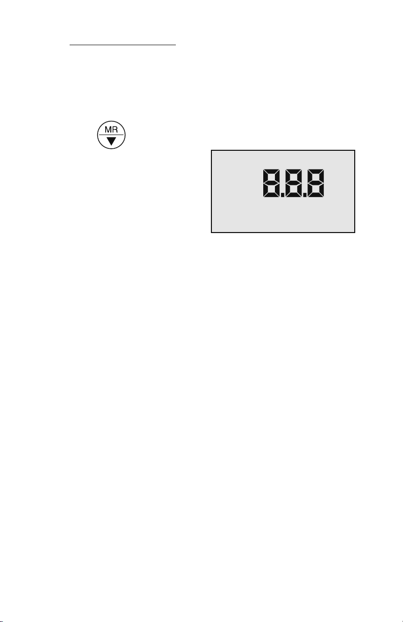
XXI. SOFTWARE VERSION
Figure 17
Contact the Myron L Company to see if a software upgrade is available.
1. Press any measurement key.
2. Press key until three numbers are displayed as shown
in Figure 17.
3. Press any measurement
key, instrument will time out in
~20 seconds.
34
Page 39

XXII. GLOSSARY
Anions Negatively charged ions.
See Solution Characteristics, pg. 30.
Algorithm A procedure for solving a mathematical problem.
See Temperature Compensation and TDS Derivation,
pg. 31.
Logarithm An arithmetic function. See pH Units, pg. 32.
TDS Total Dissolved Solids or the Total Conductive Ions
in a solution. See Conductivity Conversion to TDS,
pg. 30.
Tempco Temperature Compensation
See Temperature Compensation, pg. 27.
For details on specic areas of interest refer to the Table of Contents.
35
Page 40

XXIII. ADDENDUM
36
Page 41

37
Page 42

XXIV. NOTES
38
Page 43

39
Page 44

MYRON L COMPANY
2450 Impala Drive
Carlsbad, CA 92010-7226
USA
Tel: 1-760-438-2021
Fax: 1-760-931-9189
www.myronl.com
Made In USA
 Loading...