

Page 1
RPR pH/ORP SENSOR REPLACEMENT INSTRUCTIONS
For Ultrameter™ 6P, 3P, Ultrameter II™ 6P, 6Psi, 6Pfc, Ultrameter III™ 9P
PoolPro™ PS6, PS6si and D-6 Digital Dialysate Meter™
NOTE: Please read these instructions thoroughly and carefully — Damage caused by improper installation or mishandling will void
the warranties of the instrument and the new sensor.
CAUTION: Moisture trapped in instrument will cause damage. Careful adherence to the following procedure will signicantly reduce
the potential for failure due to moisture contamination.
Enclosed with this new sensor is a new orange O-ring, and a protective foam, install per instructions in III. 8. below. While the
instrument is open, we recommend you replace the battery with a 9V alkaline type. For clarity, this procedure is broken down into
four sections. Follow each section carefully to avoid damage. Refer to drawings on reverse as necessary.
I. Preparing and Opening Instrument Case.
1. Remove pH/ORP protective cap from sensor well, shake out uid and dry sensor well thoroughly.
2. If the instrument is wet, dry it thoroughly before proceeding, paying particular attention to the bottom screw
holes. Ensure hands are clean and dry. Moisture will damage the electronics.
3. Turn instrument over and set on a clean, dry surface.
4. Using a Phillips screwdriver, remove the 4 bottom screws.
5. Open instrument carefully, on Ultrameter it may be necessary to rock the bottom case side to side to release it
from the RS-232 connector. While removing bottom case ensure sealing gasket does not stick to bottom, but stays
in top case groove. If gasket comes out, handle carefully and reinstall in top case groove.
Exercise extreme care not to allow any water to enter the open case.
II. Disconnecting and Removing Old pH/ORP Sensor.
1. Locate the cable connectors and disconnect (unscrew using a 1/4 in. open-end wrench) both cables from the
circuit board noting position of RED pH cable. Red cable is on the left. See drawing B.
2. If you are right handed, hold the instrument in your left hand with the rounded end up and locate the pH/ORP
sensor and locking tab. See drawings B & C.
3. Using your left thumb, press the locking tab away from the sensor or toward the circuit board (the tab need
only be moved approximately 1/16 in./1,5 mm).
4. While holding locking tab back, pull straight out on the cables and body of the sensor, wiggling slightly if
necessary. Once the sensor moves upwards, you may let go of the tab and pull the sensor completely out.
5. Remove any pieces of the old seal and wipe out all dirty residue from the sensor well.
6. Thoroughly inspect and clean both top and bottom case (paying special attention to the case seal and O-rings),
screw wells and screws.
III. Preparing and Installing New pH/ORP Sensor
1. Install new ORANGE O-ring in sensor well. See drawing C.
Steps 2-4 should be performed AWAY from instrument.
2. Remove tape from around new sensor and protective boot. CAUTION: Protective boot is lled with a concentrated
saline storage solution that will cause damage if allowed to come in contact with internal components.
3. Carefully remove protective boot from new sensor by lightly squeezing top half of boot and executing a slow
twisting pull. Inspect to ensure 2 O-rings are on sensor body.
4. Rinse sensor with clean water and dry thoroughly. Inspect to ensure 2 O-rings are on sensor body.
5. Align sensor with case (it will only go in one way — see drawings B & C). Ensure both O-rings on sensor slide
evenly into sensor well. CAUTION: A damaged O-ring will allow water to leak into case.
6. Press sensor into sensor well until an audible snap is heard and locking tab is in place. See drawing C.
7. Reconnect the cables in their respective places: Red cable on the left, Black on the right. Tighten securely.
8. Remove existing protective foam (light colored) from the bottom case, peel backing from new protective foam, and
install inside bottom case in same location.
IV. Closing Instrument Case
1. Align cables so that they will NOT obstruct or become pinched while reinstalling the bottom case.
2. Ensure the sealing gasket is installed in the groove of the top case.
3. Replace bottom, aligning it with the groove.
4. Install and start the 4 bottom screws.
5. Tighten screws evenly and securely. A waterproof seal cannot be ensured unless screws are secure.
Uneven tightening will cause instrument to rock.
6. Turn instrument over and ll pH/ORP sensor well with Myron L pH/ORP Sensor Storage Solution. If unavailable,
use a pH 4 Buffer or a saturated solution of table salt and tap water.
7. Reinstall protective cap on pH/ORP sensor well.
Your instrument is now ready for calibration. See Operation Manual, Pocket Card or Bottom Label for calibration instructions.
2450 Impala Drive
Carlsbad, CA 92010-7226 USA
Tel: +1-760-438-2021
Fax: +1-800-869-7668 / +1-760-931-9189
www.myronl.com
RPRI r10-17
Page 2
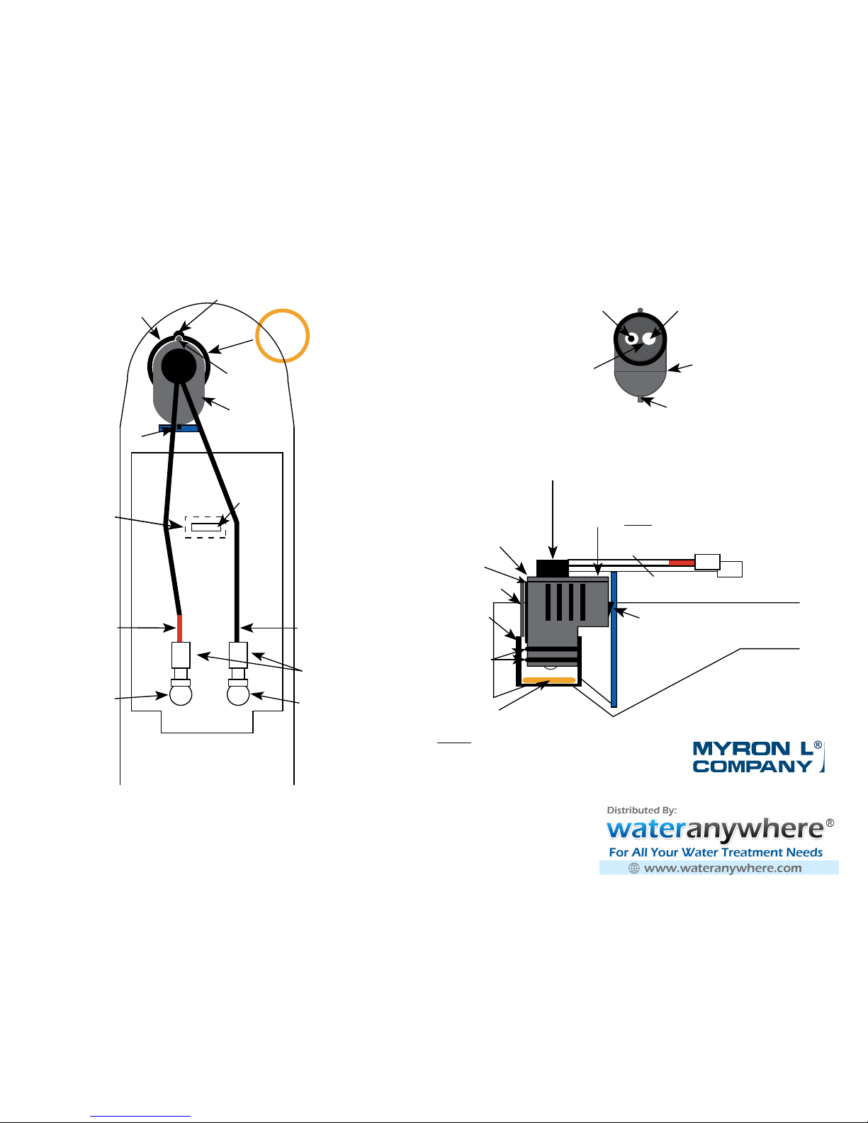
TOP VIEW
ORP
Electrode
pH Glass
Electrode
Sensor
Body
Locking Tab
Reference
Junction
under
Glass Bulb
A
Alignment Guide
pH
ORP
Red
Cable
Locking Tab
pH/ORP Sensor Body
Black
Cable
UM:
Center
Connector
(RS-232)
Connectors
B
Sensor Well
Install ORANGE
O-ring in Sensor
Well before
installing
sensor.
INTERIOR VIEW
C
Connectors
Sensor
Body
ORP
pH
ORANGE
Sensor Well
O-ring Seal is
installed below
the sensor
Locking Tab
Sensor Well
SIDE VIEW
Cut-Away
Alignment Guide
Circuit
Board
uDock
Capable
P
OOLPRO or
UMII:
IR
Transmitter
(do not
obstruct)
O-ring
Seals (2)
Align sensor rib with alignment guide (notch) in case.
Move cables aside and press
here to Snap in place.
pH/ORP SENSOR
Model RPR
Sensor Rib
Sensor Rib
W
ate r Q ualit y I nst rum ent ati o
n
Acc urac y • Re liabil ity • Simpli city
 Loading...