

Myron L ULTRAMETER III 9PTKB, POOLPRO PS9TKB Operation Manual

ULTRAMETER
Operation
Manual
MODEL 9PTKB
III
™
®
24 July 2019

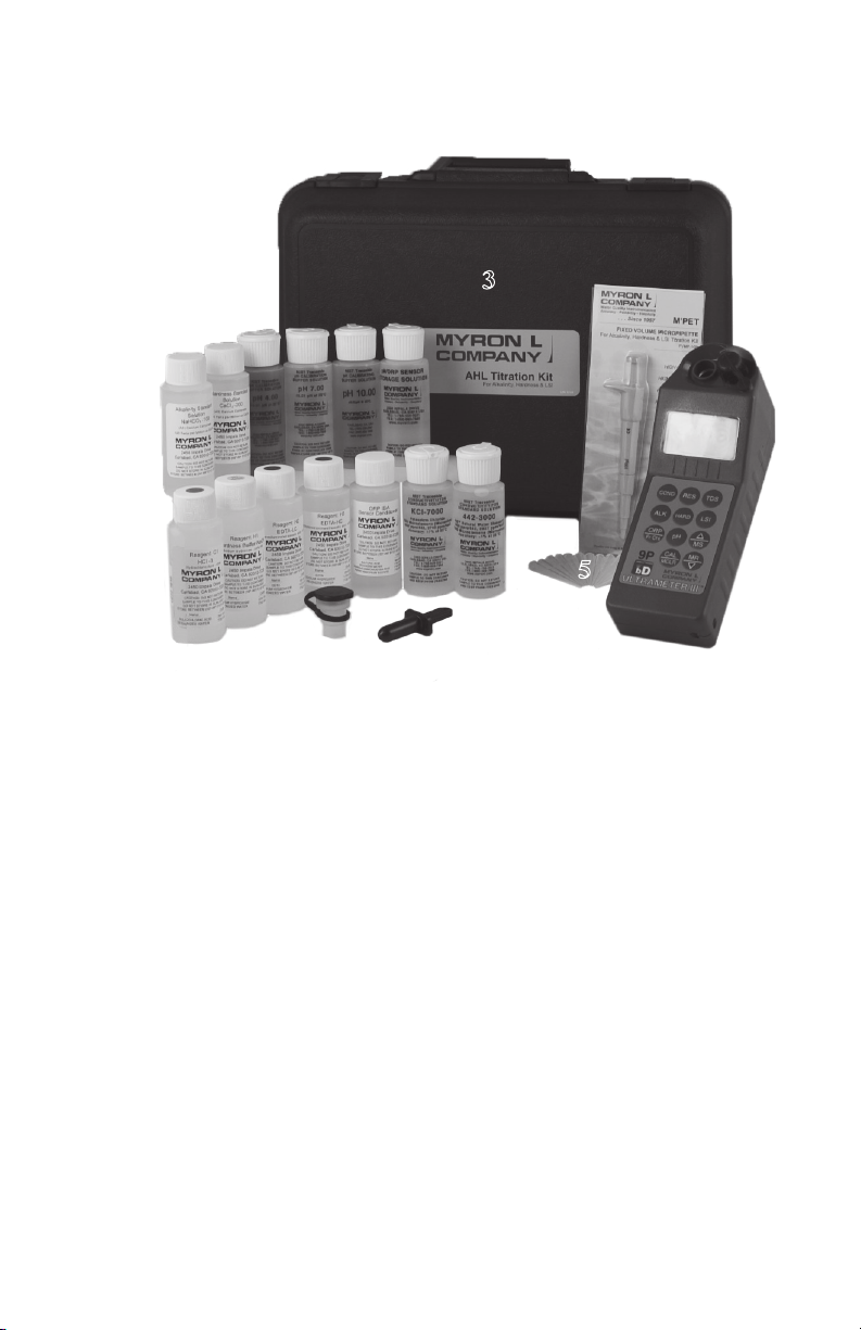
THE 9P TITRATION KIT (WITH BLUDOCKTM OPTION)
COMES WITH EVERYTHING YOU SEE HERE
3
4
10 11
9
8
7
6
1
18
17
16
15
14
13
12
5
2
19
PLEASE CHECK THE CONTENTS OF YOUR KIT!
1. Ultrameter III™ Model 9P-BD
2. Cell Extender Model TKCE
3. Foam-lined hard carry case
4. M’PET 100µL xed volume pipette Model FVMP-100
5. 12 disposable pipette tips
6. 2oz. bottle of Alkalinity Standard Solution Model ALK-1002OZ
7. 2oz. bottle of Hardness Standard Solution Model HARD-2002OZ
8. 2oz. bottle of pH 4 buffer Model PH42OZ
9. 2oz. bottle of pH 7 buffer Model PH72OZ
10. 2oz. bottle of pH 10 buffer Model PH102OZ
11. 2oz. bottle of pH/ORP Sensor Storage Solution Model SS2OZ
12. 2oz. bottle of Alkalinity Reagent A1 Model H2SO4-12OZ
13. 2oz. bottle of Hardness Reagent HB, Model HBUFF2OZ
14. 2oz. bottle of Hardness Reagent H4, Model EDTA-B-LC2OZ
15. 2oz. bottle of Hardness Reagent H5, Model EDTA-B-HC2OZ
16. 1oz. bottle of ORP ISA Sensor Conditioner Model ORPCOND1OZ
17. 2oz. bottle of KCl-7000 Model KCL-70002OZ
18. 2oz. bottle of 442-3000 Model 442-30002OZ
19. Titration T-plunger Model TPLUNGER
i
ii

I. INTRODUCTION
Thank you for selecting the feature-packed Ultrameter III™, one of the
Myron L® Company’s latest in an increasing line of instruments utilizing
advanced microprocessor-based circuitry and SMT manufacturing
processes. This circuitry makes the instrument extremely accurate,
reliable and very easy to use.
The Ultrameter III has been designed to include titration measurements
for Alkalinity, Hardness and an LSI Calculator for water balance analysis.
The Ultrameter III also features Myron L® Company's exclusive Free
Chlorine Equivalent (FC
TM
E
) function for making ORP-based free chlorine
measurements, as well as optional Bluetooth® wireless data transfer.
Other features include a clock with time and date, memory of up to 100
locations with time and date stamp, the ability of the user to adjust the
timeout “Auto OFF”, and enhanced performance. See Features and
Specications on pages 2-3.
The most exciting feature is data logging with the ability to wirelessly
download the memory or stored test data with its corresponding time, date
and unit name (requires -BD option or bluDockTM accessory). This feature
allows the user to create spreadsheets and graphs with ease, and quickly
and accurately manipulate data more effectively. The bluDock's Guardian
TM
2 TM
application will operate on Windows® 7 or later/macOS® 10.13 or later with
Bluetooth® capability. The data may be exported to spreadsheet formats
such as Microsoft Excel® (.xls and .xlsx) or universal formatting (.csv). The
user can also save data in a secure, encrypted format (.mlcx).
Please Note: Although the Myron L® Company has performed extensive
testing, we cannot guarantee compatibility of all applications and
formats. We suggest testing your application and format for compatibility
before relying on it.
For your convenience, a brief set of instructions is provided on the
bottom side of your Ultrameter III. A Quick Start Guide with abbreviated
instructions is also included with the instrument as a quick reference.
Special note ... Conductivity, resistivity, and TDS require mathematical
correction to 25°C values (ref. Temperature Compensation, pg. 56). On
the left of the Ultrameter III’s liquid crystal display is shown an indicator of
the salt solution characteristic used to model temperature compensation
of conductivity and its TDS conversion. The indicator may be KCl,
NaCl, 442™ or User. Selection affects the temperature correction of
conductivity and the calculation of TDS from compensated conductivity
(ref. Conductivity Conversion to Total Dissolved Solids (TDS), pg. 59).
The selection can affect the reported conductivity of hot or cold solutions
and will change the reported TDS of a solution. Using KCl for conductivity,
NaCl for resistivity, and 442™ (Natural Water characteristic) for TDS is
consistent with present industry practice for standardization. This is how
your instrument, as shipped from the factory, is set to operate. For use in
seawater desalination for example, both the conductivity and TDS may
easily be changed to NaCl.
1

II. FEATURES and SPECIFICATIONS
A. Features
• ORP-based FCE Free Chlorine measurement; displays as ppm
concentration
• Alkalinity and Hardness Conductometric Titrations
• Langelier Saturation Index (LSI) Calculator
• Superior resolution 4 digit LCD displays full 9999 µS/ppm
• Cond/TDS Accuracy of ±1% of READING / ±0.1% at calibration point
• All electrodes are internal for maximum protection
• Improved 4-electrode sensor technology
• Waterproof to 1 meter/3 feet
• Autoranging conductivity/TDS/resistivity
• Prompts for easy pH calibration
• Factory calibrations stored in microprocessor
• 3 conductivity/TDS solution conversions preprogrammed into
microprocessor
• User mode feature allows:
Programming your own Cond/TDS conversion factor
Programming your own temperature compensation factor
Disabling temperature compensation
• Real Time Clock with Time and Date
• Data Logging with TIME and DATE in memory
• Memory stores 100 readings
• User adjustable timeout “Auto OFF”
• Bluetooth® wireless download capability with optional bluDock™
accessory package
B. General Specications
Display 4 Digit LCD
Dimensions (LxWxH) 196 x 68 x 64 mm/
7.7 x 2.7 x 2.5 in.
Weight 352 g/12.4 oz.
Case Material VALOX*
Cond/Res/TDS Cell Material VALOX*
Cond/TDS Electrodes (4) 316 Stainless Steel
Cond/Res/TDS Cell Capacity 5 ml/0.17 oz.
pH/ORP Sensor Well Capacity 1,2 ml/0.04 oz.
Power 9V Alkaline Battery
Battery Life >100 Hours/5000 Readings
Operating/Storage Temperature 0-55°C/32-131°F
Protection Ratings IP67/NEMA 6 (waterproof to
1 meter/3 feet)
EMI/EMC Ratings EN61326-1: 2006 + Annex A: 2008
(hand-held devices)
(Conformité Européenne)
IEC 61000-4-2: 2001 and,
IEC 61000-4-3: 2002
* ™ SABIC Innovative Plastics IP BV
Additional information is available on our website:
CISPR 11: 2003
www.myronl.com
MADE IN USA
2
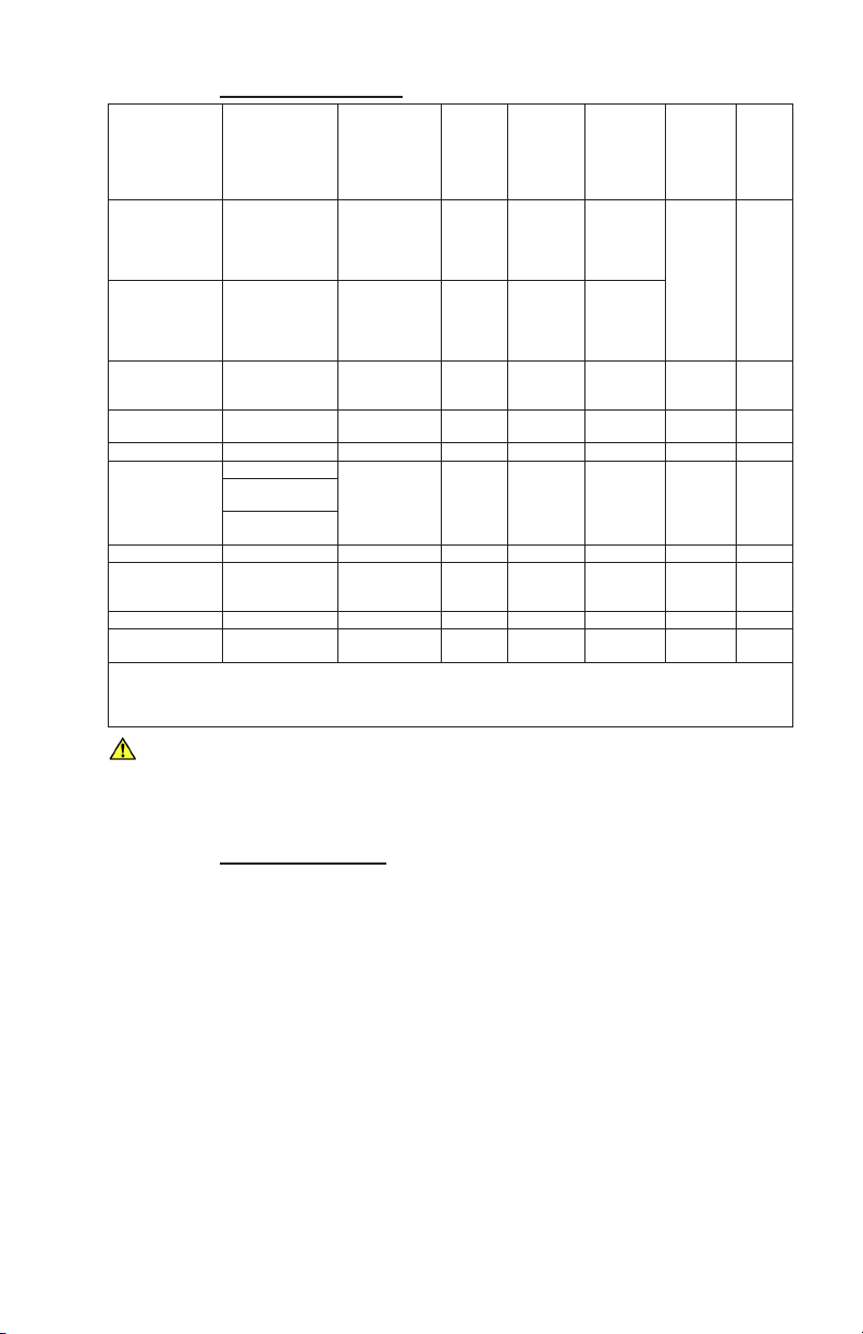
C. Specication Chart
*
*
*
Auto
Temperature Compensation
0-71ºC
32-160ºF
0-71ºC
32-160ºF
0-71ºC
32-160ºF
0-71ºC
32-160ºF
0-71ºC
32-160ºF
Parameters Ranges Resolution
0.01(<100µS)
0.1(<1000µS)
1(<10mS)
0.01(<100mS)
0.1(<200mS)
0.01(<100ppm)
0.1(<1000ppm)
1(<10ppt)
0.01(<100ppt)
0.1(<200ppt)
0.01(<100KΩ)
0.1(<1000KΩ)
0.1(>1MΩ)
0.01ppm
0.1(<1000 ppm)
1(<1710 ppm)
0.1(<100 grains)
0.1ºC/ºF ±0.1ºC
350≤ORPmV<725
)
725≤ORPmV<825
0-9999µS/cm
10-200mS/cm
in 5 autoranges
0-9999ppm
10-200ppt
in 5 autoranges
0.00-9.99ppm**
and 0.0≤pH<9.9
and 0.0≤pH<8.9
0-1710ppm
(0-100 grains)
0-71ºC
32-160ºF
Conductivity
TDS
Resistivity 10KΩ-30MΩ
pH 0-14pH 0.01pH ±0.01pH
ORP ±999mV 1mV ±1mV
Free Chlorine
Equivalent
TM
E
(FC
Alkalinity Titration 10-800ppm 0.1ppm
Hardness Titration
LSI Calculator -10 to +10 0.01
Temperature
*EM Susceptibility: When Measuring 10.0 pH Reference Solution
±0.2 pH in the presence of RF elds ≥ 3 V/m.
±0.37 pH in the presence of RF elds at 300 MHz (±30MHz)
**If either ORP or pH is outside the specied limits, the instrument will display "-Or-".
Accu-
racy
±1% of
reading
±1% of
reading
±1% of
reading
±0.3ppm
<1.00ppm*
±0.2ppm
≥1.00ppm
Adjustable
Temperature Compensation
0-9.99%/ºC
0-9.99%/ºC
0-9.99%/ºC
Cond/TDS
Ratios
Prepro-
grammed
KCl, NaCl,
442™
Adjust-
able
Cond/
TDS
Ratio
Factor
0.20-
7.99
WARNING: These products can expose you to chemicals including
Di(2-ethylhexyl)phthalate (DEHP), which is known to the State of
California to cause cancer and birth defects or other reproductive harm.
For more information go to www.P65Warnings.ca.gov
D. Warranty/Service
The Myron L® Ultrameter III, excluding the pH/ORP sensor, has a Two
(2) Year Limited Warranty. The pH/ORP sensor has a Six (6) Month
Limited Warranty for materials and workmanship. If an instrument fails
to operate properly, see Troubleshooting Chart, pgs. 52-53. The battery,
pH/ORP sensor and cell extender are user-replaceable. For other
service, return the instrument prepaid to the Myron L® Company.
MYRON L® COMPANY
2450 Impala Drive
Carlsbad, CA 92010-7226 USA
+1-760-438-2021
E-Mail: info@myronl.com
techquestions@myronl.com
www.myronl.com
If, in the opinion of the factory, failure was due to materials or
workmanship, repair or replacement will be made without charge. A
reasonable service charge will be made for diagnosis or repairs due to
normal wear, abuse or tampering. This warranty is limited to the repair or
replacement of the Ultrameter III only. The Myron L® Company assumes
no other responsibility or liability.
3

E. Ultrameter
Model
III
Ultrameter III Model 9P
PARAMETERS
Conductivity/Resistivity/TDS/Alkalinity/Hardness/LSI/ORPmV/
Free Chlorine Equivalent (FCE) ppm/pH/Temperature
PLEASE NOTE:
Because of our commitment to product improvement, the substance and
style of this manual may change. When changes are made, the updated
manual is posted for download in PDF format from the Myron L® Website:
www.myronl.com
4

TABLE OF CONTENTS
9PTK Contents ............................................i
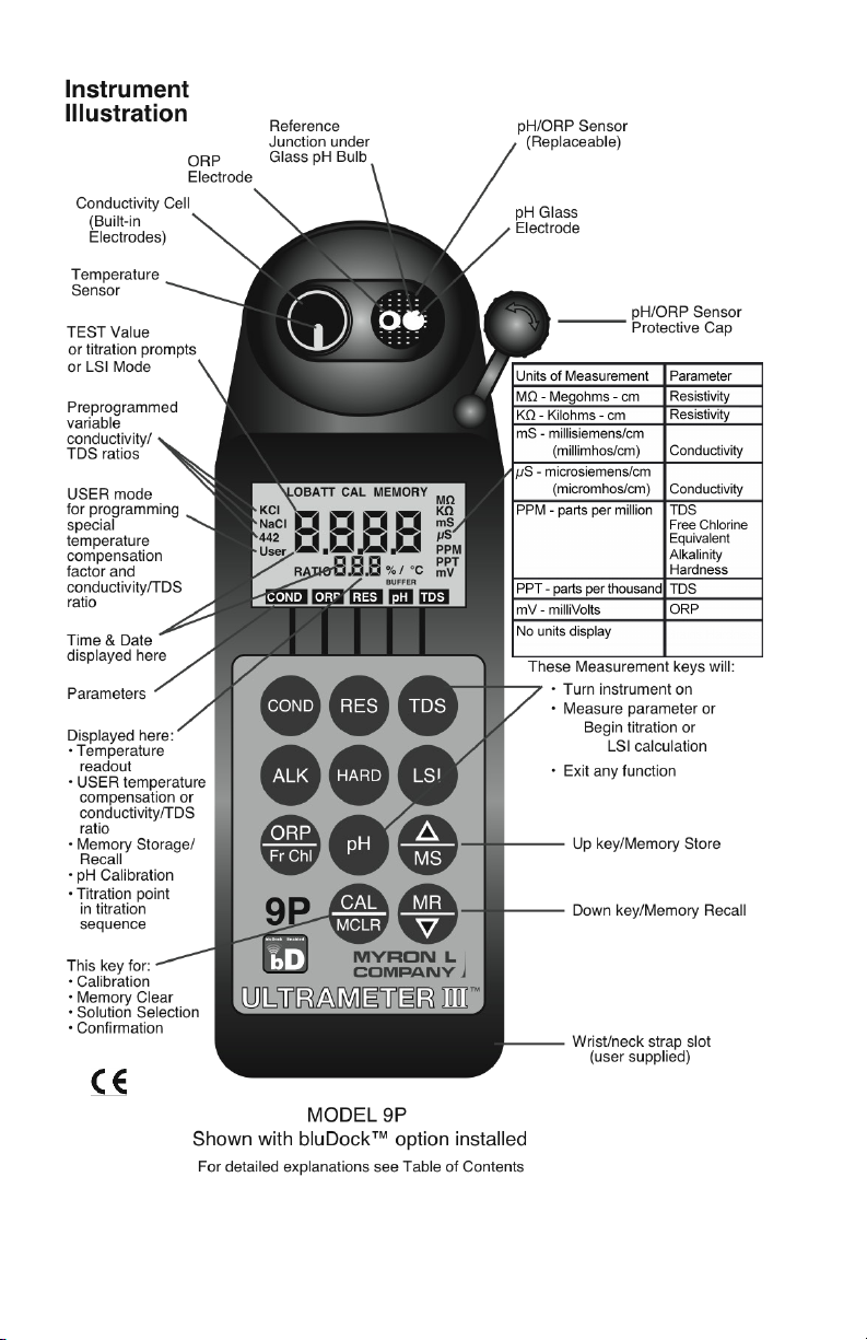
Instrument Illustration ...................................... ii
I. INTRODUCTION ................................... 1
II. FEATURES and SPECIFICATIONS ....................2
A. Features ................................2
B. General Specications .....................2
C. Specication Chart ........................3
D. Warranty/Service..........................3
E. Ultrameter III Model .......................3
III. RULES of OPERATION..............................8
A. Operation ...............................8
B. Characteristics of the Keys ..................8
C. Operation of the Keys ......................8
1. Measurement Keys in General......... 8
2. COND, RES and TDS Keys ........... 9
3. Alkalinity, Hardness and LSI Keys . . . . . . 9
4. pH and ORP/FCE Keys ...............10
5. CAL/MCLR Key ...................10
6. UP or DOWN Keys................. 10
IV. AFTER USING THE ULTRAMETER III................. 11
A. Maintenance of the Conductivity Cell ......... 11
B. Maintenance of the pH/ORP Sensor.......... 11
V. SPECIFIC RECOMMENDED MEASURING
PROCEDURES ...................... 11
A. Parameter Methods....................... 11
B. Titration Methods......................... 11
1. Pipette Instructions................. 12
2. T-plunger Instructions...............13
3. Mixing Solution in Cell ..............13
C. Measuring Conductivity &
Total Dissolved Solids (TDS) ............ 14
D. Measuring Resistivity .....................14
E. Measuring Alkalinity ......................14
F. Measuring Hardness......................16
1. Hardness Unit Selection............. 16
2. Select EDTA Reagent...............16
3. Hardness Titration Procedure ........16
G. LSI Calculator Functions...................18
1. Measuring LSI ....................19
2. Hypothetical LSI Calculations ........19
H. Measuring pH ...........................19
I. Measuring ORP..........................20
1. ORP/FCE Mode Selection ...........20
2. Measuring ORP ...................21
J. Measuring FCE ..........................21
1. Prepare for FCE Measurement ........ 21
2. FCE Flow Method ..................21
3. FCE Immersion Method .............22
4. FCE Best Practices ................. 23
5

VI. SOLUTION SELECTION ............................ 23
A. Why Solution Selection is Available .......... 23
B. The 4 Solution Types ..................... 23
C. Calibration of Each Solution Type ............ 23
D. Procedure to Select a Solution ..............23
E. Application of User Solution Type ............24
1. User Programmable Temperature
Compensation (Tempco) ........24
2. Disabling Temperature Compensation ...25
3. User Programmable Conductivity to
TDS Ratio .................... 25
VII. CALIBRATION....................................26
A. Calibration Intervals ......................26
B. Rules for Calibration of the Ultrameter III ......26
1. Calibration Steps ..................26
2. Calibration Limits ..................28
C. Calibration Procedures ....................28
1. Conductivity or TDS Calibration ....... 28
2. User Calibration Conductivity/TDS..... 28
3. Resistivity Calibration...............29
4. Reloading Factory Calibration
(Cond or TDS) ................29
5. Alkalinity Calibration................29
6. Hardness Calibration ...............31
7. pH Calibration ....................33
8. ORP Calibration ...................35
9. Temperature Calibration.............35
VIII. CALIBRATION INTERVALS .........................35
A. Suggested Intervals ......................35
B. Calibration Tracking Records ...............35
C. Conductivity, RES, TDS Practices............36
D. pH and ORP/FCE Practices.................36
IX. MEMORY........................................36
A. Memory Storage .........................36
B. Memory Recall ..........................37
C. Clearing a Record/Memory Clear ............37
X. TIME and DATE................................... 38
A. Setting TIME ............................38
B. Setting DATE............................39
C. DATE FORMAT “US & International (Int)” ...... 40
XI. TEMPERATURE FORMAT “Centigrade & Fahrenheit” .....41
XII. TOTAL RETURN to FACTORY SETTINGS..............41
XIII. CELL CHECK ....................................42
XIV. AUTO OFF ......................................43
XV. USER MODE CALIBRATION LINC™ FUNCTION ........44
A. Calibration of Ultrameter III for use in
User mode .......................... 44
B. Setting User mode Calibration “Linc” .........45
C. Canceling User mode Calibration “Linc” .......46
XVI. bluDock™ Wireless Data Transfer Instructions...........47
6
A. Software Installation ......................47

B. Hardware Setup .........................47
C. Memory Stack Download ..................48
XVII. CARE and MAINTENANCE ......................... 49
A. Temperature Extremes ....................49
B. Battery Replacement......................49
C. pH/ORP Sensor Replacement .............. 50
D. Cleaning Sensors ........................50
XVIII. TROUBLESHOOTING .............................52
XIX. ACCESSORIES................................... 54
A. Conductivity/TDS Standard Solutions ......... 54
B. Titration Standard Solutions ................54
C. Titration Reagent Solutions ................. 55
D. pH Buffer Solutions .......................55
E. pH Sensor Storage Solution ................55
F. ORP Sensor Conditioner Solution............55
G. Soft Protective Carry Cases ................55
H. Hard Protective Carry Cases ...............56
I. Replacement pH/ORP Sensor ..............56
J. Pipette Kit with Replacement Tips............ 56
K. Replacement M’Pet Pipette.................56
L. M’Pet Pipette Replacement Tips.............56
M. bluDockTM Wireless Data Transfer
Accessory Package................... 56
XX. TEMPERATURE COMPENSATION (Tempco)
of Aqueous Solutions.................. 56
A. Standardized to 25°C .....................56
B. Tempco Variation.........................57
C. An Example of 2 different solution selections
and the resulting compensation.......... 57
D. A Chart of Comparative Error ...............58
E. Other Solutions ..........................58
XXI. CONDUCTIVITY CONVERSION to
TOTAL DISSOLVED SOLIDS (TDS) ......59
A. How it’s Done ...........................59
B. Solution Characteristics ...................59
C. When does it make a lot of difference? ........ 60
XXII. TEMPERATURE COMPENSATION (Tempco)
and TDS DERIVATION ................60
A. Conductivity Characteristics ................60
B. Finding the Tempco of an Unknown Solution ...61
C. Finding the TDS Ratio of an Unknown Solution ... 61
XXIII. pH and ORP/FCE..................................62
A. pH ....................................62
B. ORP/Oxidation-Reduction Potential/REDOX ...64
C. FCE ...................................65
XXIV. ALKALINITY, HARDNESS AND LSI ................... 66
A. Alkalinity and Hardness Titrations............66
B. Langelier Saturation Index .................66
C. Hardness Units ..........................67
XXV. SOFTWARE VERSION .............................67
XXVI. GLOSSARY...................................... 68
7

III. RULES of OPERATION
A. Operation
NOTE: The cell extender does not interfere with normal operation.
Using the instrument is simple:
• Individual or multiple parameter readings may be obtained by
lling individual sensors or entire cell cup area.
• Rinse the conductivity cell and/or pH/ORP sensor well with test
solution 3 times and rell. Temperature and/or measurement
extremes will require additional rinses for maximum accuracy.
• Press the desired measurement key to start measurement.
• For titrations, user intuitive display prompts guide you through
the addition of reagents and measurements.
• Pressing any parameter key again in measurements restarts
the 15 second “Auto off” timer. Pressing any parameter key
again during titrations will cancel the titration in progress.
• Note the value displayed and/or press the MS key to store the
reading (ref. Memory Storage, pg. 36). It’s that simple!
B. Characteristics of the Keys
• Though your Ultrameter III has a variety of sophisticated
options, it is designed to provide quick, easy, accurate
measurements by simply pressing a key.
• All functions are performed one key at a time.
• THERE IS NO “OFF” KEY. If the instrument remains inactive
for 15 seconds after you press any parameter key (user
adjustable up to 75 seconds), the instrument turns itself off.
The instrument turns itself off after 60 seconds of inactivity in
CAL mode, 3 minutes of inactivity in each titration screen and
60 seconds of inactivity in each LSI calculator value screen.
• Rarely is it necessary to press and hold a key (as in Procedure
to Select a Solution, pg. 23; Conductivity or TDS Calibration,
pg. 28; and ORP/FCE Mode Selection, pg. 20).
C. Operation of the Keys (See Instrument Illustration, pg. ii)
1. Measurement Keys in General
Any of the 8 measurement keys turns on the instrument in the mode
selected. The mode is shown at the bottom of the display for COND,
RES, TDS, ORP and pH. The ORP mode is indicated by the units
displayed, mV for ORP or ppm for free chlorine. Measurement units
appear at the right. Pressing any measurement key puts the unit in that
measurement mode even if you are in a calibration sequence and also
serves to cancel a change (ref. Leaving Calibration, pg. 27).
8
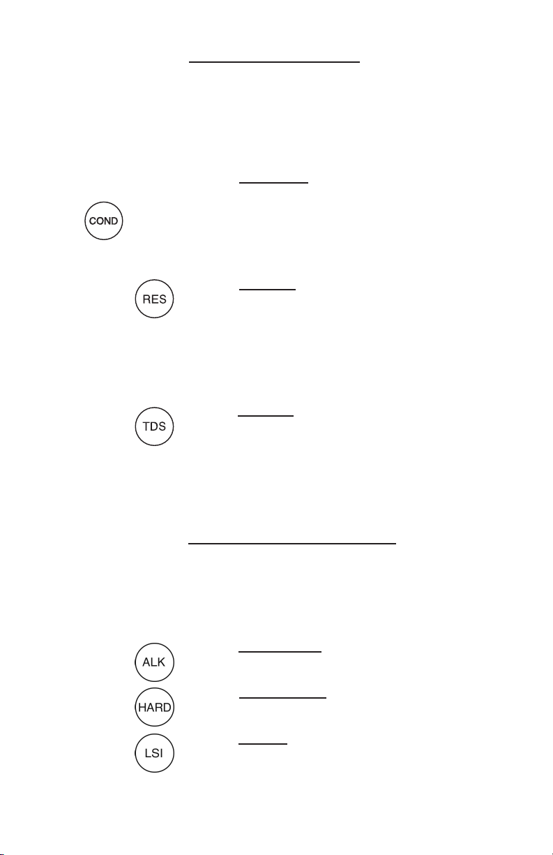
2. COND, RES and TDS Keys
These 3 keys are used with solution in the Conductivity Cell.
Precautions:
• While lling cell cup, ensure no air bubbles cling on the cell wall.
• If the proper solution is not selected (KCl, NaCl, 442™ or
User), refer to Why Solution Selection is Available, pg. 23 and
Procedure to Select a Solution, pg. 23.
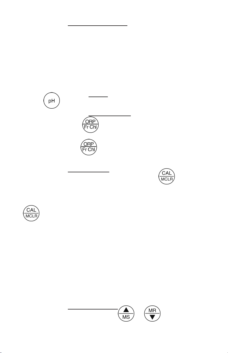
a. COND Key
Solution to be tested is introduced into the conductivity cell and a press
of displays conductivity with units on the right. On the left is
shown the solution type selected for conductivity.
b. RES Key
A press of
is shown solution type selected for resistivity (ref. Solution Selection,
pg. 23). The range of display of resistivity is limited to between 10
kilohms (KΩ) and 30 megohms (MΩ). A solution outside that range will
only show [- - - -] in the display.
c. TDS Key
A press of
This is a display of the concentration of ionized material calculated from
compensated conductivity using the characteristics of a known material.
On the left is shown solution type selected for TDS (ref. Solution
Selection, pg. 23).
displays resistivity with units on the right. On the left
displays Total Dissolved Solids with units on the right.
3. Alkalinity, Hardness and LSI Keys
The ALK and HARD keys enter the titration measurement functions. The
LSI key also allows you to access the LSI Calculator.
NOTE: All titration measurements require the installation of the cell
extender.
a. Alkalinity Key
A press of
b. Hardness Key
A press of
c. LSI Key
A press of
used to measure LSI by pulling the most recent alkalinity, hardness, pH
and temperature values or for hypothetical water balance adjustments.
enters the Alkalinity titration function.
enters the unit in the Hardness titration function.
enters the unit in LSI calculator mode, which can be
9
4. pH and ORP/FC Keys
E
Measurements are made on solution held in the pH/ORP sensor well
(ref. pH and ORP/FCE, pg. 62). The protective cap is removed and
the sensor well is lled and rinsed with the sample enough times to
completely replace the storage solution.
After use, the pH/ORP sensor well must be relled with Myron L®
Storage Solution, and the protective cap reinstalled securely (ref.
Maintenance of the pH/ORP Sensor, pg. 11 and Cleaning Sensors, 2.
pH/ORP, pg. 50).
a. pH Key
A press of
displays pH readings. No units are displayed on the right.
b. ORP/Fr Chl Key
In ORP mode, a press of
displays Oxidation-Reduction Potential
/REDOX reading in millivolts; "mV" is displayed. When the FCE mode
is activated, a press of
reading in "ppm" alternating with the FCE predictive ORP reading in "mV".
displays the Free Chlorine Equivalent
5. CAL/MCLR Key
While measuring conductivity, TDS, or pH, a press of
allows
you to enter the calibration mode. Once in CAL mode, a press of this
key accepts the new value. If no more calibration options follow, the
instrument returns to measuring (ref. Leaving Calibration, pg. 27).
If is held down for about 3 seconds, CAL mode is not entered,
but “SEL” appears to allow Solution Selection (ref. pg. 23) with the UP
or DOWN keys. As in calibration, the CAL key is now an “accept” key.
While measuring ORP or Free Chlorine, holding CAL down for about
3 seconds allows ORP/FCE mode selection (ref. pg. 20).
For titrations and LSI Calculator, the CAL key steps you through the
procedure and accepts values for nal calculations.
Once in CAL mode, a press of this key accepts the new value.
While reviewing stored records, the MCLR side of the key is active to
allow clearing records (ref. Clearing a Record/Memory Clear, pg. 37).
6. UP or DOWN Keys
While measuring in any parameter, the or
keys activate
the Memory Store and Memory Recall functions. A single press steps
the display and holding either key scrolls the value rapidly.
10

While in calibration or calculator mode, the keys step or scroll the
displayed value up or down.
While in Memory Recall, the keys scroll the display up and down
through the stack of records (ref. Memory Recall, pg. 37).
IV. AFTER USING THE ULTRAMETER
A. Maintenance of the Conductivity Cell
Rinse out the cell cup with clean water. Do not scrub the cell. For
oily lms, squirt in a foaming non-abrasive cleaner and rinse (ref.
Cleaning Sensors, pg. 50). Even if a very active chemical discolors
the electrodes, this does not affect the accuracy; leave it alone.
B. Maintenance of the pH/ORP Sensor
The sensor well must be kept wet. Before replacing the rubber cap,
rinse and ll the sensor well with Myron L® pH Sensor Storage Solution.
Although not ideal, if Myron L® Storage Solution is not available, you
can temporarily use a strong KCl solution, a pH 4 Buffer Solution, or a
saturated solution of table salt and tap water until pH Storage Solution is
obtained. NEVER use distilled water.
If all ORP solutions are reporting approximately the same value,
clean ONLY the platinum ORP electrode with an MLC ORP
conditioner-soaked cotton swab, being careful not to touch the
swab to the glass bulb of the pH sensor.
V. SPECIFIC RECOMMENDED MEASURING PROCEDURES
A. Parameter Methods
For Conductivity and Total Dissolved Solids measurements, if the
proper solution is not selected (KCl, NaCl, 442TM or User), see Solution
Selection, pg. 23.
III
NOTE: After sampling high concentration solutions or temperature
extremes, more rinsing may be required. When sampling low
conductivity solutions, be sure the pH cap is well seated so that no
solution washes into the conductivity cell from around the pH cap.
B. Titration Methods
For Alkalinity, Hardness titrations, assemble the required materials
before you begin: a pipette with 100µL tips, the required reagents, the
cell extender, and the T-plunger.
11
NOTE: The accuracy of titration measurements
Plunger Button
is affected by your technique. Be careful when
removing the cap of the cell extender to add
reagents. Flicking the cap or popping it off can
Plunger Rod
cause solution to spill out of the cell extender.
Always use a new pipette tip when changing
solutions to avoid contamination.
CE
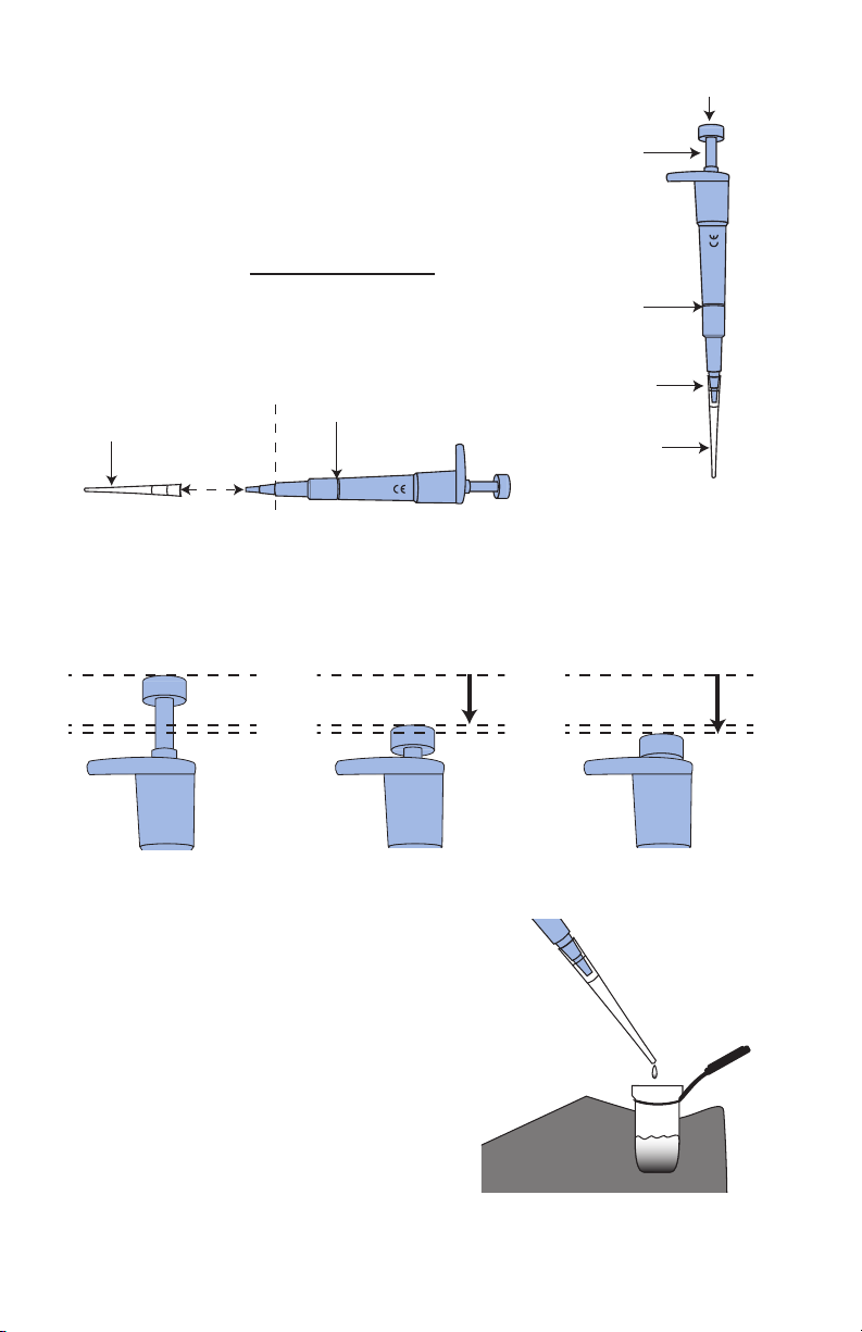
1. Pipette Instructions
100µl
Always use a clean tip when changing
solutions! To install a tip, press the wide end of
Shaft Coupling
100 µL
the tip on the end of the pipette until it is secure.
Avoid contaminating the pipette tips. To remove
a tip, simply pull it off the end of the pipette.
Disposable Tip
Shaft Coupling
100µl
100 µL
Pipette Assembly
CE
Shaft Bottom
Disposable Tip
Fully Assembled Pipette
NOTE: Do NOT twist the cap off as this may unscrew the shaft bottom
from the pipette.
The pipette has 3 positions: REST, FIRST STOP, and SECOND STOP.
Practice pushing in and letting up on the pipette to feel the different
positions.
Rest Position: The
plunger is all the way
U P.
First Stop: The plunger
is depressed until
resistance is felt.
a. To DRAW a
sample: Grasp the pipette by the shaft
with your hand. Rest your thumb on top
of the plunger button. Use your thumb
to depress the top of the pipette to the
FIRST STOP. Insert the tip end down into
sample until only the tip is submerged,
about 2-3mm / 1/8". Slowly release the
top and let it return to the REST position
being careful to keep the tip submerged.
b. To
DISPENSE a sample: With the pipette
in the REST position, place the tip end
12
Second Stop: The
plunger is depressed all
the way DOWN.
Do not allow the pipette tip to touch
the cell wall or the sample.

over the conductivity cell being careful
not to touch the tip to the existing
solution. Depress the top of the pipette
to the SECOND STOP (all the way
down) being careful to keep the tip over
the cell. Release the plunger button and
let it return to the REST position.
2. T-Plunger Instructions
To PLUNGE the cell:
Clean and dry the T-plunger. With the
cell extender installed and solution in
the cell, insert the tip of the T-plunger
in the cell extender until the arms of the
T-plunger are ush against the rim of the
cell extender. Solution will overow the
cell.
Keeping the arms of the T-plunger ush
against the rim of the cell extender, rotate
the T-plunger from side to side, allowing
the arms of the T-plunger to slide along
the rim of the cell extender.
Remove the T-plunger from the cell by
lifting it straight up out of the cell, being
careful to keep it centered over the mouth
of the cell extender. When the T-plunger
is completely out of solution, tap the
T-plunger on the inside rim of the cell
extender to dispel any clinging solution
back into the cell.
Insert the T-plunger all the way
down into the cell extender then
rotate it from side to side.
Hold the T-plunger over the cell
then tap rmly so that solution is
dispelled back into the cell cup.
Remove the T-plunger completely from
the cell area.
3. Mixing Solution in Cell
a. Agitate
When the display says to agitate (“AGit”):
Grasp the instrument on both sides of
the keypad (keypad facing up) with your
hands so you don’t accidentally drop or
release it. Agitate the solution in the cell
by swinging the cell cup area of the 9P up
“AGit”: When “AGit” displays, swing
the cell end of the 9P up and down
ve or more times.
and down ve or more times.
b. Hold
When the display says to hold (“HOLd”):
Hold the instrument steady in the
horizontal position while the instrument
records a measurement.
“HOLd”: When “HOLd” displays, hold
the 9P still with bottom of case parallel
to the ground.
13

C. Measuring Conductivity & Total Dissolved Solids (TDS)
1. Rinse cell cup 3 times with sample to be measured. (This
conditions the temperature compensation network and prepares
the cell.)
2. Rell cell cup with sample.
3. Press or
4. Take reading. A display of [- - - -] indicates an overrange
condition.
D. Measuring Resistivity
Resistivity is for low conductivity solutions. In a cell cup the value may
drift from trace contaminants or absorption from atmospheric gasses, so
measuring a owing sample is recommended.
1. Ensure pH protective cap is secure to avoid contamination.
2. Hold instrument at 30° angle (cup sloping downward).
3. Let sample ow continuously into conductivity cell with no aeration.
4. Press
NOTE: If reading is lower than 10 kilohms, display will be dashes:
[ - - - - ]. Measure solution Conductivity instead.
E. Measuring Alkalinity
Prepare the materials required for titration: Reagent: A1, cell extender,
T-plunger, and 100µL pipette with a clean tip installed.
NOTE: If you do not complete each titration point within the 3-minute
timeout period, the unit exits the Alkalinity function. Start the titration
process over.
key; use best reading.
.
If you make a gross error in your titration method, e.g., you forget to add
sample to the cell, “Err” will display. Start the titration over.
1. Ensure pH protective cap is secure to avoid contamination.
2. Install the cell extender by pushing the base of the cell extender
into the conductivity cell until it is fully seated.
3. Rinse the conductivity cell cup and cell extender 3 times with
solution to be measured.
4. Rell cell cup and cell extender with sample solution.
5. Insert T-plunger into open cell extender until the “T” rests ush
on the lip of the cell extender. This will cause uid beyond what
is required for titration to overow the cell extender.
14
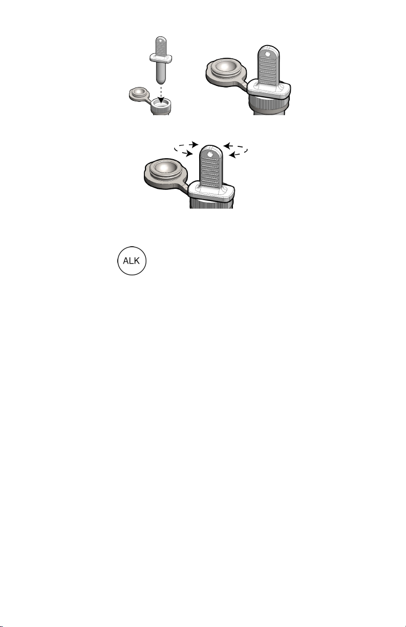
6. Rotate the T-plunger from side to side, allowing the arms of the
T-plunger to slide along the rim of the cell extender.
7. Carefully remove the T-plunger so as not to ick or spill remaining
sample. Tap the T-plunger on the inside rim of the cell extender
to remove sample that may be stuck to the T-plunger.
8. Press . “AL” alternating with “tdS” briey displays along
with the “PPM” value of the sample. “PrES CAL” will display
when the reading stabilizes.
9. Press CAL to accept and advance to the rst titration prompt.
“Add” alternating with “A1” displays.
10. Using the pipette, add 100µL of Reagent: A1, close the cell
extender cap securely, Press CAL to continue.
11. “AGit t1” ashes on the screen. Agitate to mix the sample. When
agitation is done, tap the cell extender cap to dispel any solution
clinging to the cap back into the cell. Press CAL to continue.
(The number after "t" indicates which titration point you are on.
The number "1" here indicates this is the rst titration point.
Subsequent titration points are sequenced numerically: 2, 3, 4,
etc.)
12. “HOLd” displays. Keep holding the meter steady until “Add”
alternating with “A1” displays. Open the cell extender cap carefully
to avoid spilling, and use the pipette to add 100µL of Reagent A1.
Close the cell extender cap securely. Press CAL to continue.
13. Repeat Steps 11 and 12 until the meter reports the alkalinity
result.
14. Note the value for your records or press MS to store the value.
The unit will automatically power off.
15
F. Measuring Hardness
1. Hardness Unit Selection
The 9P offers the ability to set the hardness unit preference to either
“PPM” CaCO3 or grains of hardness. To change hardness units, press
HARD, then press and hold CAL down until “HArd” and “SEL” are
displayed. Press UP or DOWN to toggle between “PPM” and grains (no
units are displayed for grains). Press CAL to accept. This also sets the
hardness unit preference for the LSI Calculator simultaneously.
2. Select EDTA Reagent
0-200 ppm- Reagent H4, EDTA-B-LC (optimal for 0-100 ppm)
0-1710 ppm- Reagent H5, EDTA-B-HC (optimal for 100-1710 ppm)
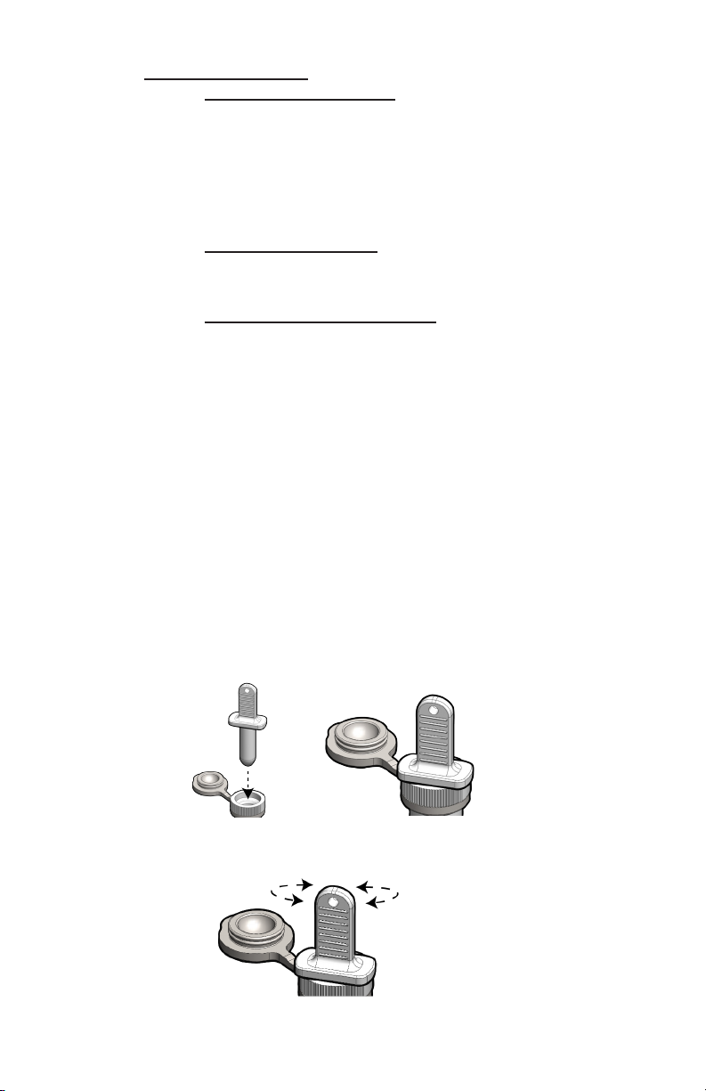
3. Hardness Titration Procedure
Prepare the materials required for titration: Reagent: HB, Reagent: H4,
or Reagent: H5, cell extender, T-plunger, 100µL pipette with a clean tip
installed, and one extra clean tip.
NOTE: If you do not complete each titration point within the 3-minute
timeout period, the unit exits the Hardness function. Start the titration
process over.
1. Ensure pH protective cap is secure to avoid contamination.
2. Install the cell extender by pushing the base of the cell extender
into the conductivity cell until it is fully seated.
3. Rinse the conductivity cell cup and cell extender 3 times with
solution to be measured.
4. Rell cell cup and cell extender with sample solution.
5. Insert T-plunger into open cell extender until the “T” rests ush
on the lip of the cell extender. This will cause uid beyond what
is required for titration to overow the cell extender.
6. Rotate the T-plunger from side to side, allowing the arms of the
T-plunger to slide along the rim of the cell extender.
16

7. Carefully remove the T-plunger so as not to ick or spill remaining
sample. Tap the T-plunger on the inside rim of the cell extender
to remove sample that may be stuck to the T-plunger.
8. Press . “CA” alternating with “tdS” displays along with
“PPM” sample value. “PrES CAL” displays when the reading
stabilizes.
9. Press CAL. "HC" or "LC" will display; use the UP or DOWN
keys to switch to HC for the higher range (0-1710 ppm) or
LC for the lower range (0-200ppm). Press CAL to accept and
continue.
10. “Add” alternating with “buFF” displays. Using the pipette, add
100µL of Reagent HB to the sample, close the cell extender cap
securely. Change the pipette tip for adding EDTA in following
steps. Press CAL to continue.
11. “AGit” ashes on the screen. Agitate to mix the sample. When
agitation is done, tap the cell extender cap to dispel any solution
clinging to the cap back into the cell. Press CAL to continue.
12. “HOLd” displays. Keep holding the meter steady until “Add”
alternating with “EdtA” displays. Open the cell extender cap
carefully to avoid spilling, and use the pipette to add 100µL of
EDTA-B-HC or EDTA-B-LC, as indicated on the display. Close
the cell extender cap securely. Press CAL to continue.
13. “AGit t1” ashes on the screen. Agitate to mix the sample. When
agitation is done, tap the cell extender cap to dispel any solution
clinging to the cap back into the cell. Press CAL to continue.
(The number after “t” indicates which titration point you are on.
The number “1” here indicates this is the rst titration point.
Subsequent titration points are sequenced numerically: 2, 3, 4,
etc.)
14. Repeat Steps 12 and 13 until the meter reports the hardness result.
15. Note the hardness value for your records or press MS to store
the value. The unit will automatically power off.
NOTE: If there is a gross error in your titration method, e.g., you forgot
to add sample to the cell, “rEAd Err” will alternate with “rEPt tit”.
Repeat the titration from Step 1 to obtain a reading. If the reading is
over range, the display indicates “Or”. If the reading is under range, the
display indicates “0.00”.
17

G. LSI Calculator Functions
The Ultrameter III features an LSI Calculator that can be used to perform
actual LSI or for hypothetical water balance calculations.
The LSI Calculator computes a Langelier Saturation Index value using
measured, default, or user-adjusted values for alkalinity, hardness, pH
and temperature.
If you have stored alkalinity, hardness or pH and temperature values,
the calculator will automatically display the most recent stored value. All
other values will display as default. You can adjust any or all of the values
displayed to determine the effect of the change(s) on the LSI value.
1. Measuring LSI
To compute the actual saturation index of a solution:
Before you enter the calculator function, you must measure and store
values for all water balance variables used by the calculator to compute
saturation index.
1. Perform an alkalinity titration of the sample solution (ref.
Measuring Alkalinity, pg. 14). Press MS to store the reading in
memory.
2. Perform a hardness titration of the sample solution (ref.
Measuring Hardness, pg. 16). Press MS to store the reading in
memory.
3. Measure the pH of the sample solution (ref. Measuring pH, pg.
19) Press MS to store the reading in memory.
4. Press
5. The last stored alkalinity value is displayed.
6. Press CAL to accept value and advance to the hardness value
screen. The last stored hardness value is displayed.
7. Press CAL to accept value and advance to the pH value screen.
The last stored pH value is displayed.
8. Press CAL to accept value and advance to the temperature
value screen. The last stored temperature value (taken from
the last stored hardness or alkalinity titration) is displayed.
9. Press CAL to accept and calculate LSI. The saturation index
value will display. Press MS to store the reading. The unit will
automatically power off after the period of inactivity dened in
the AUTO OFF setting (ref. AUTO OFF, pg. 43).
18
.

If you want to modify any of the input values and recalculate LSI based
on those changes, press CAL again and repeat Steps 5-9 using the UP
and DOWN keys to change the values. If you want to change hardness
units (ppm/grains), you must do so in the hardness parameter. See
Hardness Unit Selection, pg. 16.
2. Hypothetical LSI Calculations
To compute saturation index using hypothetical alkalinity, hardness, pH
or temperature values:
1. Press
2. Either the last stored value or the default value of “120” is
displayed.
3. Press the UP or DOWN keys to adjust the alkalinity value or
leave as displayed.
4. Press CAL to accept and advance to the hardness value
screen. Either the last stored value or the default value of “166”
is displayed.
5. Press the UP or DOWN keys to adjust the hardness value or
leave as displayed.
6. Press CAL to accept hardness value and advance to the pH
value screen. Either the last stored value or the default value of
“7.20” is displayed.
7. Press UP or DOWN to adjust the pH value or leave as displayed.
8. Press CAL to accept pH value and advance to the temperature
value screen. Either the last stored value (taken from the last
stored hardness or alkalinity titration) or the default value of
“25 ºC” is displayed.
9. Press UP or DOWN to adjust the temperature value or leave as
displayed.
10. Press CAL to accept and calculate LSI. A saturation index value
will display.
If you want to modify any of the input values and recalculate LSI based
on those changes, press CAL again and repeat Steps 3-10. If you want
to change hardness units, you must do so in the hardness parameter.
See Hardness Unit Selection, pg. 16.
.
H. Measuring pH
1. Remove protective cap by rotating while grasping and pulling up.
2. Rinse pH/ORP sensor well and conductivity cell cup 3 times
with sample to be measured. Shake out each sample to remove
any residual liquid.
19
 Loading...