

Page 1

TechPro
™
Operation
Manual
Model pH1
MYRON L
COMPANY
10-02 (WEB) EG
Page 2
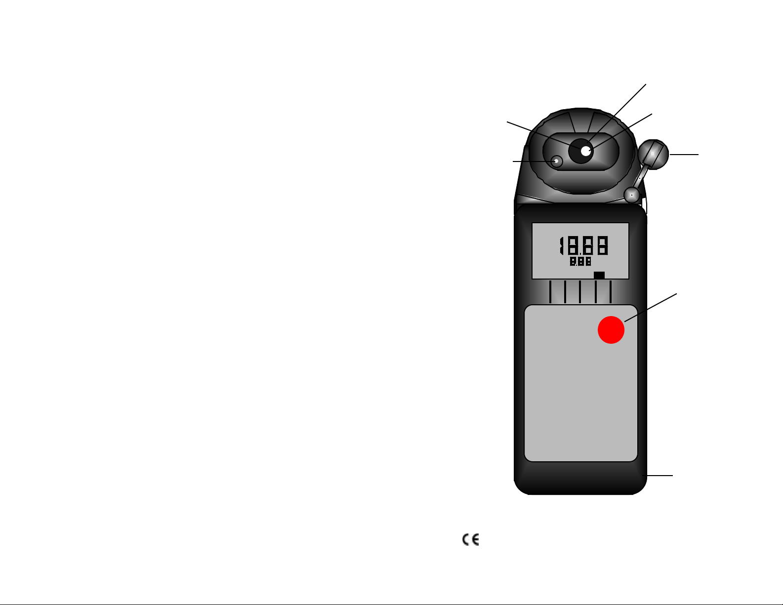
Instrument Illustration
Reference
Junction
(under Glass
Bulb)
pH Sensor
(User replaceable)
pH Glass
Electrode
Temperature
Sensor
pH Sensor
Protective Cap
LO BATT
°C
pH
Measurement key
pH
pH Meter
pH1
MYRON L
COMPANY
For detailed explanations, see Table of Contents
Wrist/neck strap slot
(user supplied)
10-26-98
1
Page 3
FEATURES and SPECIFICATIONS
A. Features
• Superior resolution 3 1/2 digit LCD
• Accuracy of ± .05 pH units
• All electrodes are internal for maximum protection
• Latest sensor technology
• Water resistant
• Easy calibration
• Temperature Accuracy of ±1° C/F
B. General Specifications
Display 3 1/2 Digit LCD
Dimensions (LxWxH) 7.7x2.7x2.5 in.
196x68x64 mm
Weight 10.8oz./310g
Case Material ABS
pH Sensor Well Capacity 0.04 oz./1.2 ml
Power 9V Alkaline Battery
Battery Life >100 Hours/5000 Readings
Operating/Storage Temperature 32-132°F/0-55°C
Protection Ratings IP64/NEMA 3
D. Warranty/Service
The pH1, has a 2 year warranty excluding the pH sensor which has a
limited 6 month warranty. If an instrument fails to operate properly, see
Troubleshooting Chart, pg. 12. The battery and pH sensor are user-replaceable
For other service, return the instrument prepaid to the Myron L Company.
MYRON L COMPANY
2450 Impala Drive
Carlsbad, CA 92010
USA
760-438-2021
If, in the opinion of the factory, failure was due to materials or
workmanship, repair or replacement will be made without charge. A
reasonable service charge will be made for diagnosis or repairs due to
normal wear, abuse or tampering. This warranty is limited to the repair or
replacement of the pH1 only. The Myron L Company assumes no other
responsibility or liability.
E. TechPro™ Series Models
TechPro Series Models pH1 AR1 ARH1
Parameters pH Conductivity or TDS, Conductivity or TDS,
& Temperature & Temperature pH & Temperature
C.Specification Chart
Additional information available on our web site at:
pH1 pH Temperature
Range 0-14 pH 0-71° C
32-160° F
Resolution .01 pH 0.1° C/F
Accuracy ±.05 pH ±1.0° C/F
Auto Temperature 0-71° C
Compensation 32 - 160° F
www.myronl.com
2 3
Page 4

TABLE OF CONTENTS
Instrument Illustration . . . . . . . . . . . . . . . . . . . . . . . . . . . . . . . . . . . . . . . . . . . .1
FEATURES and SPECIFICATIONS. . . . . . . . . . . . . . . . . . . . . . . . . 2
A. Features . . . . . . . . . . . . . . . . . . . . . . . . . . . . . . . . . . . . . . 2
B. General Specifications . . . . . . . . . . . . . . . . . . . . . . . . . . 2
C. Specification Chart . . . . . . . . . . . . . . . . . . . . . . . . . . . . . 2
D. Warranty/Service . . . . . . . . . . . . . . . . . . . . . . . . . . . . . . .3
E. TechPro Series Models . . . . . . . . . . . . . . . . . . . . . . . . .3
X. ACCESSORIES . . . . . . . . . . . . . . . . . . . . . . . . . . . . . . . . . . . . . . . . 13
A. pH Buffer Solutions . . . . . . . . . . . . . . . . . . . . . . . . . . . 13
B. pH Sensor Storage Solution. . . . . . . . . . . . . . . . . . . . 13
C. Soft Protective Case . . . . . . . . . . . . . . . . . . . . . . . . . . 13
D. Replacement pH Sensor . . . . . . . . . . . . . . . . . . . . . . 13
E. Conductivity/TDS Standard Solutions . . . . . . . . . . . 13
XI. pH MEASURING . . . . . . . . . . . . . . . . . . . . . . . . . . . . . . . . . . . . . . . .13
XII. GLOSSARY . . . . . . . . . . . . . . . . . . . . . . . . . . . . . . . . . . . . . . . . . . . .16
I. INTRODUCTION . . . . . . . . . . . . . . . . . . . . . . . . . . . . . . . . . . . . . . . . .6
II . RULES of OPERATION. . . . . . . . . . . . . . . . . . . . . . . . . . . . . . . . . . . 6
III. AFTER USING the pH1. . . . . . . . . . . . . . . . . . . . . . . . . . . . . . . . . . . .6
IV. THE SPECIFIC RECOMMENDED MEASURING
PROCEDURES . . . . . . . . . . . . . . . . . . . . . . . . . . . . . . . . . . .6
V. CALIBRATION . . . . . . . . . . . . . . . . . . . . . . . . . . . . . . . . . . . . . . . . . . .7
A. Calibration Intervals . . . . . . . . . . . . . . . . . . . . . . . . . . . . .7
B. Rules for Calibration in the pH1 . . . . . . . . . . . . . . . . . . .7
1. Calibration Steps. . . . . . . . . . . . . . . . . . . . . . . . 7
2. Calibration Limits . . . . . . . . . . . . . . . . . . . . . . . . 7
C. Calibration Procedures. . . . . . . . . . . . . . . . . . . . . . . . . . 7
1. pH Zero Calibration . . . . . . . . . . . . . . . . . . . . . .7
2. pH Gain Calibration . . . . . . . . . . . . . . . . . . . . . . 8
VI. CALIBRATION INTERVALS . . . . . . . . . . . . . . . . . . . . . . . . . . . . . . . 9
A. Suggested Intervals . . . . . . . . . . . . . . . . . . . . . . . . . . . . 9
B. Calibration Tracking Records. . . . . . . . . . . . . . . . . . . . . 9
C. Practices to Maintain Calibration . . . . . . . . . . . . . . . . . . 9
VII. CHANGING from CENTIGRADE to FAHRENHEIT . . . . . . . . . . . . . 9
NOTES . . . . . . . . . . . . . . . . . . . . . . . . . . . . . . . . . . . . . . . .. . . . . . . . 17
VIII. CARE and MAINTENANCE . . . . . . . . . . . . . . . . . . . . . . . . . . . . . . .10
A. Temperature Extremes . . . . . . . . . . . . . . . . . . . . . . . . 10
B. Battery Replacement (LO BATT) . . . . . . . . . . . . . . . . 10
C. pH Sensor Replacement . . . . . . . . . . . . . . . . . . . . . . .10
D. Cleaning Sensor . . . . . . . . . . . . . . . . . . . . . . . . . . . . . .10
IX. TROUBLESHOOTING . . . . . . . . . . . . . . . . . . . . . . . . . . . . . . . . . . .12
4 5
Page 5

I. INTRODUCTION
Thank you for selecting the TechPro™ Series, Model pH1, one of the
Myron L Company’s latest in a new line of digital instruments utilizing
advanced circuitry. This circuitry makes it very accurate and easy to use
(see pages 2 & 3 for Features and Specifications on this and other
models). For your convenience, on the bottom side of your pH1 is a brief
set of instructions.
4. Press .
5. Take reading.
6. IMPORTANT: After use, fill pH sensor well with Myron L
Storage Solution, a strong KCl solution or pH 4 buffer, and
replace protective cap. Do not allow pH sensor to dry out.
pH
II. RULES of OPERATION
Using the instrument is simple:
• Rinse the pH sensor well with test solution 3 times.
• Refill and Press the RED pH key.
• Note the value displayed. It’s that simple!
Your pH1 is designed to provide quick, easy, accurate measurements by
simply pressing one key.
Measurements are made on solution held in the pH sensor well (ref. pH
Measuring, pg. 13). The protective cap is removed, and the sensor well is
filled and rinsed with sample enough times to completely replace the
storage solution. After use, the pH sensor well must be refilled with
Myron L Storage Solution, and the protective cap reinstalled securely
(ref. Cleaning Sensor, pg. 10).
A press of displays pH readings. No units are displayed.
III. AFTER USING the pH1
Rinse out the cell cup with clean water. Do not scrub the sensor. For oily
films, squirt in a foaming non-abrasive cleaner and rinse.
The sensor well must be kept wet with a solution. Before replacing the
rubber cap, rinse and fill the sensor well with (in order of preference):
Myron L Storage Solution, an almost saturated KCl solution, pH 4 buffer,
(ref. Buffer Solutions, pg. 13) or at least a strong table salt solution. Not
distilled water.
IV. THE SPECIFIC RECOMMENDED MEASURING
1. Remove protective cap by squeezing its sides and pulling up.
2. Rinse sensor well 3 times with sample to be measured. Shake
pH
PROCEDURES
out each sample to remove any residual liquid.
NOTE: If a storage solution, KCl or pH 4 solution is unavailable, use a
saturated solution of table salt and water (ref. Cleaning Sensor, pg. 10).
In the first four sections, you have learned all
you need to make accurate measurements.
The following sections contain calibration and
technical information.
V. CALIBRATION
A. Calibration Intervals
Depending on frequency of use and type of solutions tested, generally,
calibration is recommended about twice per month.
B. Rules for Calibration in the pH1
1. Calibration Steps
Both Zero and Gain calibrations are accomplished by Calibration Controls
located under their respective cap plugs located on the bottom of the
instrument, one for Zero, and one for Gain.
After pressing the pH key, the reading is changed/adjusted to match the
known buffer value.
2. Calibration Limits
In pH, the inability to calibrate may indicate improper or contaminated
buffer solution or a damaged pH Sensor.
C. Calibration Procedures
IMPORTANT: Always “zero” your pH1 with a pH 7 buffer solution
before adjusting the gain with acid or base buffers, i.e. 4 and/or 10, etc.
1. pH Zero Calibration
1. Remove protective cap.
2. Rinse sensor well 3 times with 7 buffer solution.
3. Refill sensor well with sample.
6 7
3. Refill sensor well with 7 buffer solution.
Page 6

4. Press to verify the pH calibration. (If the display reads 7.00,
pH
finger until reading agrees with buffer solution.
skip the pH Zero Calibration and proceed to section b. pH Gain
Calibration. If reading is not acceptable, continue.
5. Remove cap plug labeled ZERO CAL on bottom of Instrument.
NOTE: If the pH reading displayed will not adjust to the proper reading,
the sensor well needs additional rinsing or fresh buffer solution, or the pH
sensor is bad and needs to be replaced. (ref. Troubleshooting Chart, pg.
12)
6. Refill sensor well again with 7 buffer solution.
7. While pressing the key, adjust ZERO CAL Control with
finger until the display reads 7.0.
8. Replace bottom cap plug securely to maintain water resistance.
The pH ZERO Calibration procedure is now complete. You may continue
with pH Gain Calibration or stop and replace with storage solution & pH cap.
IMPORTANT: Always calibrate or verify your pH1 with a pH 7 buffer
solution before adjusting the gain with acid or base buffers, i.e., 4 and/or
10, etc. The pH gain calibration is performed in the same manner as the
ZERO. For maximum accuracy use a buffer value closest to instrument’s
normal area of use, i.e., if you normally measure acidic solutions, use “4”
buffer.
1. Rinse the sensor well 3 times with acid or base buffer solution.
pH
b. pH Gain Calibration
7. If the instrument will be used to read both acids and bases,
repeat steps 1 and 6 using opposite buffer solution.
8. If reading is different by more than is acceptable, split the
difference with the previous setting. (If it is not possible to
adjust Gain, it is an indication of bad buffers or a deteriorating
or damaged pH sensor).
9. Replace bottom cap plug securely to maintain water resistance.
The pH GAIN Calibration procedure is now complete.
VI. CALIBRATION INTERVALS
There is no simple answer as to how often one should calibrate an
instrument. The pH1 is designed to not require frequent recalibration.
The most common sources of error were eliminated in the design, and
there are simple electromechanical adjustments. Still, to ensure specified
accuracy, any instrument has to be checked against chemical standards
occasionally.
A. Suggested Intervals
On the average, calibration should be checked every 2 weeks to ensure
accuracy. Measuring some solutions will require more frequent intervals.
B. Calibration Tracking Records
To minimize your calibration effort, keep records. If adjustments you are
making are minimal for your application, you can check less often.
Changes in pH calibration are best recorded in pH units. Calibration is
purposely limited in the pH1 to approximately ±1 pH unit because more
than that indicates the end of the sensor lifetime, and it should be
replaced.
2. Refill sensor well again with same buffer solution.
1. Keep the sensor wet with pH storage solution.
3. Press key. If reading is acceptable, end procedure. If
not, continue.
4. Remove cap plug labeled GAIN CAL on bottom of Instrument.
5. Refill sensor well again with same buffer solution.
6. While pressing the , adjust GAIN CAL Control with
8 9
pH
pH
2. Rinse away caustic solutions immediately after use.
VII. CHANGING from CENTIGRADE to FAHRENHEIT
1. Dry Instrument THOROUGHLY.
2. Remove the 4 bottom screws and carefully open Instrument.
C. Practices to Maintain Calibration.
(Note: °F to °C is the reverse)
Page 7

3. Locate dip switch labeled “TEMP COMP” on the right side of the
circuit board. Note: Factory setting is degrees “C”.
4. Set switch number 4 to the down position.
5. Carefully turn instrument over and press the key. The
pH
displayed reading will be in Fahrenheit “°F”.
oil, dirt, or scale in the cell cup or on the sensor, use a foaming nonabrasive household cleaner. Rinse out the cleaner, and your pH1 is ready
for accurate measurements.
The unique pH sensor in your pH1 is a nonrefillable combination type
which features a porous liquid junction. It should not be allowed to dry
out. If it does, the sensor can sometimes be rejuvenated by first cleaning
the sensor well with a liquid spray cleaner such as Windex™ or Fantastic™
and rinsing well. Do not scrub or wipe the pH sensor.
6. Replace bottom, ensuring the sealing gasket is installed in the
groove of the top half of case. Tighten screws securely.
Then use one of the following methods:
1. Pour a HOT salt solution ~60°C (140°F), preferably potassium
chloride (KCI) solution — HOT tap water with table salt (NaCl)
VIII. CARE and MAINTENANCE
will work fine — in the sensor well and allow to cool. Retest.
Or
The pH1 should be rinsed with clean water after each use. Solvents
should be avoided. Shock damage from a fall may cause instrument
failure.
2. Pour DI water in the sensor well and allow to stand for no more
than 4 hours (longer can deplete the reference solution and
damage the glass bulb). Retest.
If neither method is successful, sensor must be replaced.
A. Temperature Extremes
Solutions in excess of 160°F/71°C should not be placed in the cell cup
area; this may cause damage. The pH sensor may fracture if the pH1
temperature is allowed to go below -10°C (14°F). Care should be
exercised not to exceed rated operating temperature. Leaving the pH1 in
a vehicle or storage shed on a hot day can easily subject the instrument
to over 150°F. This will void the warranty.
"Drifting" can be caused by a film on the pH sensor bulb. Spray a liquid
cleaner such as Windex™ or Fantastic™ into the sensor well to clean it.
The sensor bulb is very thin and delicate. Do not scrub or wipe the pH
sensor.
pH Sensor
Top View
pH Glass
Electrode
B. Battery Replacement (LO BATT)
Dry Instrument THOROUGHLY. Remove the 4 bottom screws.
Open instrument. Carefully detach battery from circuit board. Replace
with 9 volt alkaline battery. Replace bottom, ensuring the sealing gasket
is installed in the groove of the top half of case. Tighten screws evenly
and securely.
Sensor
Body
Leaving high pH (alkaline) solutions in contact with the pH sensor for long
Reference
Junction
under Glass
pH Bulb
periods of time can damage it. Rinsing such liquids from the pH sensor
C. pH Sensor Replacement
Order model RPG. When ordering, be sure to include the model and
well and refilling well with Myron L Storage Solution, a saturated KCl
solution, pH 4 buffer, or a salty tap water, will extend the useful life.
serial number of your instrument to ensure receiving the proper type.
Complete installation instructions are provided with each replacement
sensor.
Samples containing chlorine, sulfur, or ammonia can "poison" any pH
electrode. If it is necessary to measure the pH of any such sample,
thoroughly rinse the pH sensor well with clean water immediately after
D. Cleaning Sensor
The cell cup should be kept as clean as possible. Flushing with clean
taking the measurement. Any sample element which will reduce (add an
electron to) silver, such as cyanide, will attack the reference electrode.
water following use will prevent buildup on sensor. However, if very dirty
samples — particularly scaling types — are allowed to dry in the cell cup, a
film will form. This film reduces accuracy. When there are visible films of
Replacement pH sensors are available only from the Myron L Company or
our authorized distributors.
10 11
Page 8

pH readings drift or respond
slowly to changes in
buffers/samples.
1. Temporary condition due to “memory” of
solution in pH sensor well for long periods.
2. Bulb dirty or dried out.
3. Reference junction clogged or coated.
Will not adjust down to pH 7.
pH sensor has lost KCl.
No response to pH changes
2. Cross-contamination from residual
pH buffers or samples in sensor well.
3. Calibration with expired pH buffers.
Sensor bulb is cracked or an electro-
mechanical short caused by an internal
crack.
Inaccurate pH readings
measurement key pressed.
1. pH calibration needed.
(ref. Calibration Procedure, pg. 7)
Symptom
No display, even though
Battery weak or not connected.
Possible Cause Corrective Action
IX. TROUBLESHOOTING CHART
X. ACCESSORIES
A. Buffer Solutions
pH buffers are available in pH values of 4, 7 and 10. Myron L Company
buffer solutions are traceable to NIST certified pH references and are
color-coded for instant identification. They are also mold inhibited and
accurate to within ±0.01 pH units @ 25°C. Order 4, 7 or 10 buffer.
B. pH Sensor Storage Solution
Myron L Storage Solution prolongs the life of the pH sensor. It is available
in quarts and gallons. Order SSQ or SSG.
C. Soft Protective Case
Padded Cordura® Nylon carrying case features a belt clip for hands-free
mobility. Order Model: UCC ® Registered trade mark of DuPont
D. Replacement pH Sensor
Model RPG is gel filled and features a unique porous liquid junction. It is
user-replaceable and comes with easy to follow instructions.
E. Conductivity/TDS Standard Solutions
For your other Myron L instruments, our NIST standard solutions are
available in a variety of salts and concentrations to fit your needs. Call or
write for information.
XI. pH MEASURING
A. pH as an Indicator
Replace pH sensor (ref. Sensor
Replacement, pg. 10)
Clean and rejuvenate sensor (ref.
Cleaning Sensor, pg. 10) and recalibrate.
If no improvement, replace pH sensor
(ref. Sensor Replacement, pg. 10).
Clean and rejuvenate sensor (ref.
Cleaning Sensor, pg. 10) and recalibrate.
If no improvement, replace pH sensor
(ref. Sensor Replacement, pg. 10).
12 13
(ref. Buffer Solutions, pg. 13 )
1. Recalibrate instrument.
2. Thoroughly rinse sensor well.
3. Recalibrate using fresh buffers.
Check connections or replace battery.
(ref. Battery Replacement, pg. 10).
pH is the measurement of Acidity or Alkalinity of an aqueous solution. It is
also stated as the Hydrogen Ion activity of a solution. pH measures the
effective, not the total, acidity of a solution.
A 4% solution of acetic acid (pH 4, vinegar) can be quite palatable, but a
4% solution of sulfuric acid (pH 0) is a violent poison. pH provides the
needed quantitative information by expressing the degree of activity of
an acid or base.
In a solution of one known component, pH will indicate concentration
indirectly. However, very dilute solutions may be very slow reading, just
because the very few ions take time to accumulate.
B. pH Units
The acidity or alkalinity of a solution is a measurement of the relative
availabilities of hydrogen (H ) and hydroxide (0H ) ions. An increase in
+-
Page 9

(H ) ions will increase acidity, while an increase in (OH ) ions will increase
-+
alkalinity. The total concentration of ions is fixed as a characteristic of
water, and balance would be 10 mol/liter (H ) and (OH ) ions in a neutral
-7 +-
solution (where pH sensors give 0 voltage).
pH is defined as the negative logarithm of hydrogen ion concentration.
Where (H ) concentration falls below 10 , solutions are less acidic than
+
neutral, and therefore are alkaline. A concentration of 10 mol/liter of (H )
would have 100 times less (H ) ions than (OH ) ions and be called an
+
-7
-9
-
alkaline solution of pH 9.
C. The pH Sensor
The active part of the pH sensor is a thin glass surface which is selectively
receptive to hydrogen ions. Available hydrogen ions in a solution will
accumulate on this surface and a charge will build up across the glass
interface. The voltage can be measured with a very high impedance
voltmeter circuit; the trick is to connect the voltmeter to solution on each
side.
The glass surface encloses a captured solution of potassium chloride
holding an electrode of silver coated with silver chloride. This is as inert a
connection as can be made from metal to an electrolyte. It still can
produce an offset voltage, but using the same materials to connect to the
solution on the other side of the membrane allows the 2 equal offsets to
cancel.
The problem is... the other side of the
membrane is some test solution,
Glass surface
H+ ions
Junction plug
not potassium chloride. The
outside electrode, also called the
Reference Junction, is of the same
construction with a porous plug in
place of a glass barrier to allow the
junction fluid to contact the test
solution without significant
migration of liquids through the
plug material. The figure to the
right shows a typical 2 component
Electrode wire
KCl solution
Electrode wire
pair. Migration does occur, and this
limits the lifetime of a pH junction from depletion of solution inside the
reference junction or from contamination. The junction is damaged by
drying out because insoluble crystals may form in a layer, obstructing
contact with test solutions. See Cleaning Sensor, pg. 10.
D. The Myron L Integral pH Sensor
The sensor in the pH1 (figure at right)
is a single construction in an easily
Glass Surface
Junction plug
replaceable package. The sensor body
holds an oversize solution supply for
KCl solution
long life. The reference junction “wick”
is porous to provide a very stable, low
+
permeability interface. It is formed in a
ring around the pH sensing electrode.
Glass
Sleeve
The construction combines all the best
features of any pH sensor known.
E. Sources of Error
Electrode wires
The basics are presented in Cleaning Sensor, pg. 10.
1. Reference Junction
The most common sensor problem will be a clogged junction because a
cell was allowed to dry out. The symptom is a drift in the “zero” setting at 7
pH. This is why the pH1 does not allow more than 1 pH unit of offset
during calibration. At that point the junction is unreliable.
2. Sensitivity Problems
Sensitivity is the receptiveness of the glass surface, which can be
diminished by a film on the surface, or a crack in the glass. These
problems also cause long response time.
3. Temperature Compensation
pH sensor glass changes its sensitivity slightly with temperature, so the
further from pH 7 one is, the more effect will be seen. A pH of 11 at 40 °C
would be off by 0.2 units. The pH1 senses the sensor temperature and
compensates the reading.
14 15
Page 10

XII. GLOSSARY
Logarithm - An arithmetic function. See pH Units, pg. 13.
For details on specific areas of interest refer to Table of Contents.
NOTES
16 17
 Loading...