

Page 1

CTCII
Water Quality Instrumentation
Accuracy • Reliability • Simplicity
CONDUCTIVITY/TDS
Chemical Treatment Controller
(Cooling Tower Controller)
Operation
Manual
14 JANUARY 05
INSTALLATION • OPERATION • MAINTENANCE
Controller Only: CTCII, & CTCIIT
Monitor/controller: CTCIID, & CTCIITD
ACCURACY • RELIABILITY • SIMPLICITY
Page 2

Page 3
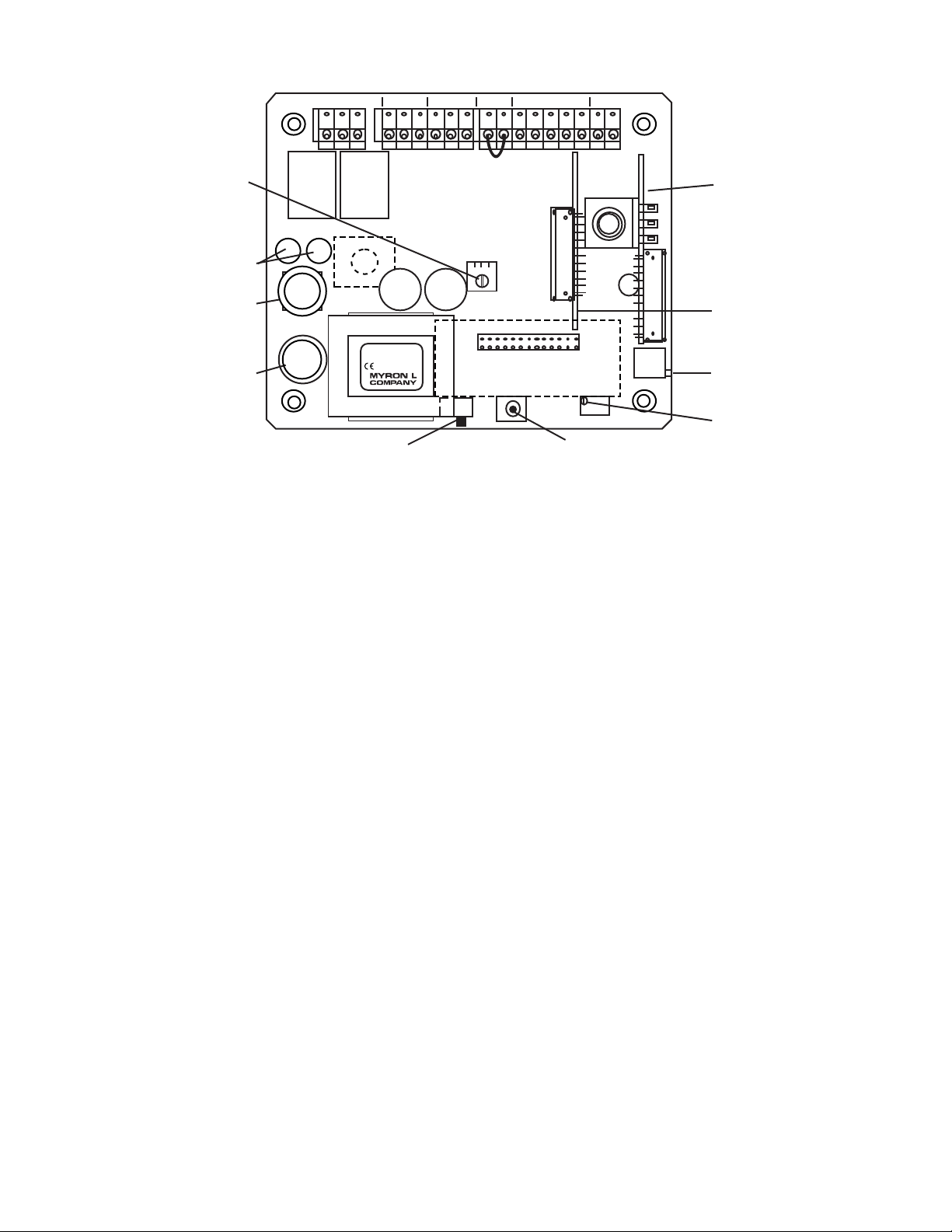
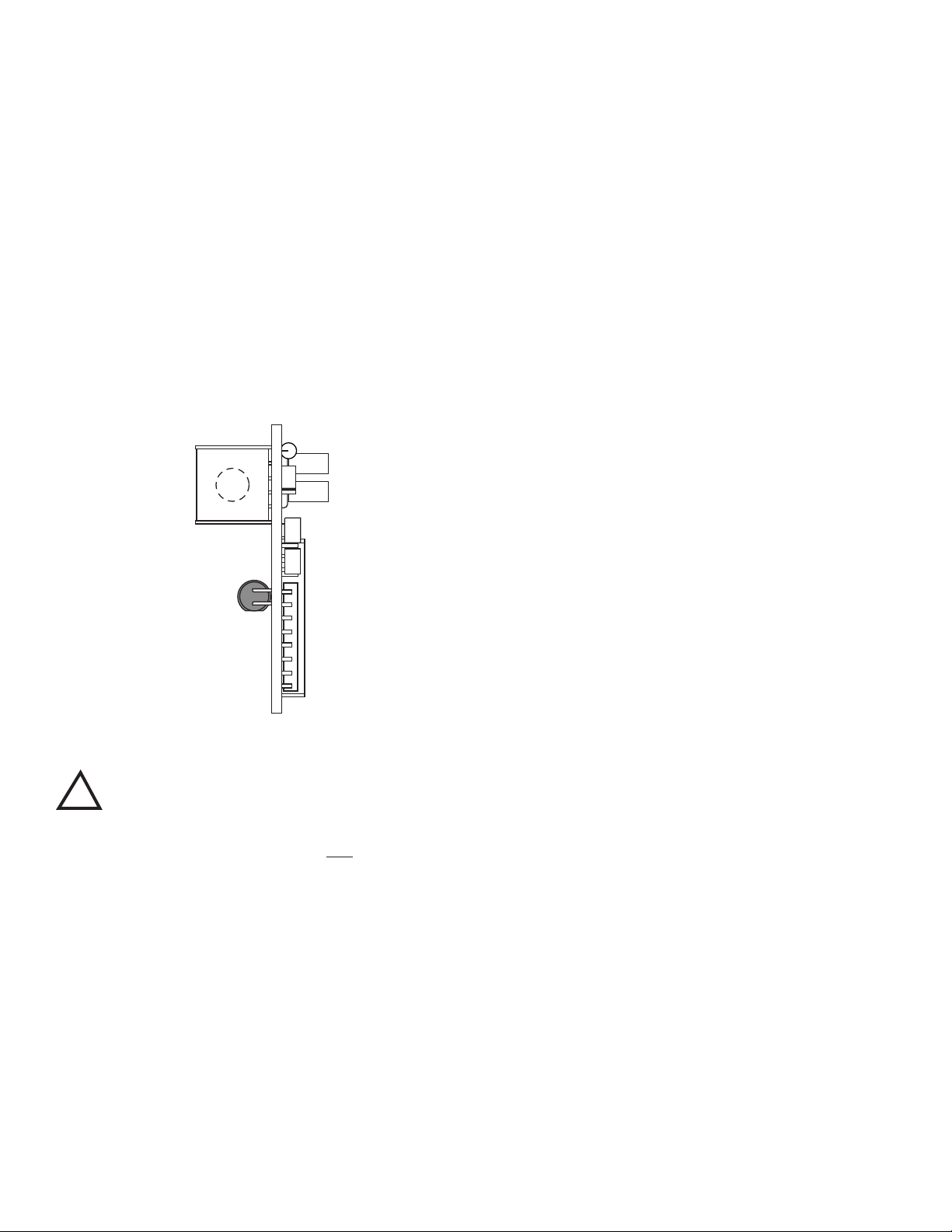
ELECTRONIC CALIBRATION (CIRCUIT ONLY) -
CTCII MAIN CIRCUIT BOARD
Figure V.A.1
115/230 VAC
SELECT SWITCH
100mA Slow Blow (T.10A)
115 & 230 VAC (V~)
Wickman Fuse 5 Amp
(#3741500041 or equiv)
115 VAC(V~)
SCALE SELECT
ELECTRONIC
CALIBRATION
MAIN
CALIBRATION
CONTROL
DISPLAY
CALIBRATION
CONTROL
(FACTORY SET)
OPTIONAL
LIMIT
TIMER
CONTROL
MODULE
OPTIONAL
4-20 mA
OUTPUT
MODULE
DIS
CAL
TDS COND
EC
CTCII
DISPLAY
TRANSFORMER
Yel
CAP CAP
C4AM
LTM
HYST
Flow Switch
Jumper Remove if
flow switch
installed.
SWITCH
FUSE
RELAY RELAY
BLEED FEED
FEED
PUMP
BLEED
VALVE
POWER
FLOW
SWITCH
SENSOR 0-10VDC
FS BK WTRD GN NU R- R+PWR C GDPWR C GDPWR C GD
SET POINT
HYSTERESIS
RIGHT INC
LEFT DEC
a. Set Point Control Calibration
1. Ensure power is OFF.
2. Using a standard slot screwdriver remove the four (4)
screws on the clear cover and remove cover.
3. The front panel is held in place with hook & loop strips
on each side. By carefully lifting at the slot on the top,
the front panel will pull toward you. Do not pull more than
about 8 inches/20CM.
DO NOT pull on control knob(s).
4. Rotate the front panel down so that the back side is
facing you. The Circuit Board is mounted to the back of
the front panel.
5. Turn power ON.
Caution: When handling CB, DO NOT touch component side.
Electrical shock may occur.
6. Press and hold the EC switch.
7. Rotate Set Point control from “0” toward EC. At EC the
relay should click, and the LED should change from RED
to GREEN. If not, set Set Point control to EC and adjust
the CALibration control.
Models with 3 1/2 digit LCD.
The display should indicate 2.50.
If not, adjust the DISplay calibration control.
8. Turn power OFF.
9. Re-install front panel and cover as described in
USING STANDARD SOLUTIONS - Section V.B.2.
The BEST method of verifying and recalibrating your CTCII
“REASSEMBLY”.
10. To operate, turn power ON.
b. 0-10VDC Recorder Output Calibration
Chemical Treatment Controller is with NIST traceable Standard
Solution (available from the Myron L Company). Because it
includes the sensor, the entire system is calibrated.
See section V.B.1.
See Section V.B.1.
The following procedure describes the easiest method for
standard solution calibration. We recommended using Myron L
442-3000 Standard Solution or equivalent. This standard solution
will calibrate either Conductivity µS (at 3900 µS) or TDS ppm (at
3000 ppm).
1. Rinse thoroughly, and ll a clean glass beaker with
standard solution.
2. Place sensor in beaker of standard solution. The level of
standard solution must be high enough to cover at least
1/2” above the electrodes.
3. Slowly shake the sensor to remove air bubbles from the
electrodes.
4. Allow 5-10 minutes for temperature to equilibrate. For
the quickest and the best results, both the sensor and
solution should be at the same temperature.
5. Turn power ON.
6. Rotated the Set Point control to 3900 for Conductivity
models or 3000 for TDS models. The relay should click
and the LED will change from GREEN to RED.
If the set point is different, adjust CALibration control
on the main circuit board until the reading matches the
solution.
Models with display (standard 3 1/2 digit).
The display should match the value of the standard
solution, 3900 µS (displayed as 3.90) or 3000 ppm
(displayed as 3.00).
If the reading is different, adjust DISplay calibration
control on the main circuit board until the reading
matches the solution.
7. After adjustment, turn power OFF.
8. Re-install front panel and cover as described below in
“REASSEMBLY”.
9. To operate, turn power ON.
TRANSFER STANDARD METHOD - See Section V.B.3.
Page 4

CTCII
CHEMICAL TREATMENT CONTROLLER
(COOLING TOWER CONTROLLER)
QUICK REFERENCE GUIDE!
If you read nothing else in this
manual please read this
Quick Reference Guide.
PLEASE READ and COMPREHEND ALL
WARNINGS, CAUTIONS and ADVISEMENTS
CONTAINED WITHIN THIS MANUAL.
Failure to comply is beyond the responsibility of the
Myron L Company.
WARNING: ALL CONTROLLERS ARE FACTORY SET TO
OPERATE ON 115 VAC. BEFORE APPLYING POWER ENSURE
THE INPUT POWER “115/230 VAC” SELECTION IS CORRECT
FOR YOUR REQUIREMENTS. FAILURE TO DO SO IS BEYOND
THE RESPONSIBILITY OF THE MYRON L COMPANY. See
section II.D.1. and gure II.E.1.
WARNING: ENSURE POWER IS OFF WHILE INSTALLING
ELECTRICAL EQUIPMENT. IF MONITOR/CONTROLLER
IS INSTALLED, ENSURE THE POWER IS OFF BEFORE
SERVICING. FAILURE TO DO SO COULD CAUSE DAMAGE
TO THE INSTRUMENT, AND COULD BE HARMFUL OR FATAL
TO PERSONNEL. ONLY QUALIFIED PERSONNEL SHOULD
INSTALL OR SERVICE ELECTRICAL EQUIPMENT.
CAUTIONS: Before installation, ensure you have the correct
model (with options), AND it is scaled for your application.
See sections I.A. & I.B.
Do you have the correct sensor? See section I.E.
Mounting requirements. What is needed? See section II.B.
The following will give the installer and user a quick
overview. See the sections listed for details.
REMOVING FRONT PANEL
1. Using a Phillips Head screwdriver remove the four (4)
screws on the clear cover.
2. Remove clear cover.
3. The front panel is held in place with hook & loop strips
on each side. By carefully lifting at the slot on the top,
the front panel will pull toward you. Do not pull more than
about 8 inches/20CM.
DO NOT pull on control knob(s).
4. Rotate the front panel down so that the back side is
facing you. The Main Circuit Board is mounted to the
back of the front panel.
REASSEMBLY
1. Carefully reinstall the front panel.
2. Reinstall the clear cover.
3. Reinstall the four (4) screws and tighten.
4. If desired, install corner covers.
5. To operate, turn power ON.
INTRODUCTION - Section I.
This section covers the specications of your new CTCII
Chemical Treatment Controller including sensor information.
INSTALLATION - Section II.
This section covers how to install your new CTCII Chemical
Treatment Controller; mechanically and electrically.
OPTIONS & ACCESSORIES - Section III.
This section covers the specications, installation, set up, and
operation of each option.
OPERATING PROCEDURES - Section IV.
This section covers a brief description of different models and
their features; how they work, and how to set them up for your
particular use.
QUICK CHECK-OUT PROCEDURE -
See Section IV.B.1.
It is assumed that the Controller power is ON, that it is connected
to an appropriate sensor, and that the sensor is immersed in water
within the range that the Controller will be required to operate, and
the clear lid is removed from the Controller.
1. Rotate the large Set Point Control knob on the front
panel through its entire range.
2. Verify that the set point indicator light changes from RED
to GREEN and visa versa.
3. Verify that the relay clicks, and controls the bleed valve
and/or chemical feed pump.
4. Adjust the set point control to the desired set point value.
5. Re-install clear cover.
HYSTERESIS (DEAD BAND) ADJUSTMENT -
See Section IV.B.3.
PRIMARY COMPONENT IDENTIFICATION -
Section V.A.
Review the gure on the following page to familiarize yourself with
the Main circuit board assembly. The diagram shows the Limit
Timer and the optional 4-20 mA Output module installed.
QUICK CALIBRATION - Section V.B.
WARNING: When performing calibration procedures, the
technician must take extreme care to avoid contacting the
circuitry other than the CALibration control. Failure to do so
could result in damage to the equipment, property and/or
personal injury.
Page 5
60
80
100
120
0
1000
2000
3000
4000
5000
40
20
0
MICROSIEMENS / CM
CTCII
EC
MINUTES
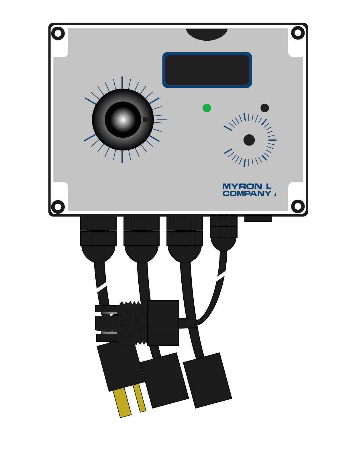
CTCII
Basic
Model
1
Page 6
60
80
100
120
0
1000
2000
3000
4000
5000
40
20
0
MICROSIEMENS / CM
CTCII
EC
MINUTES
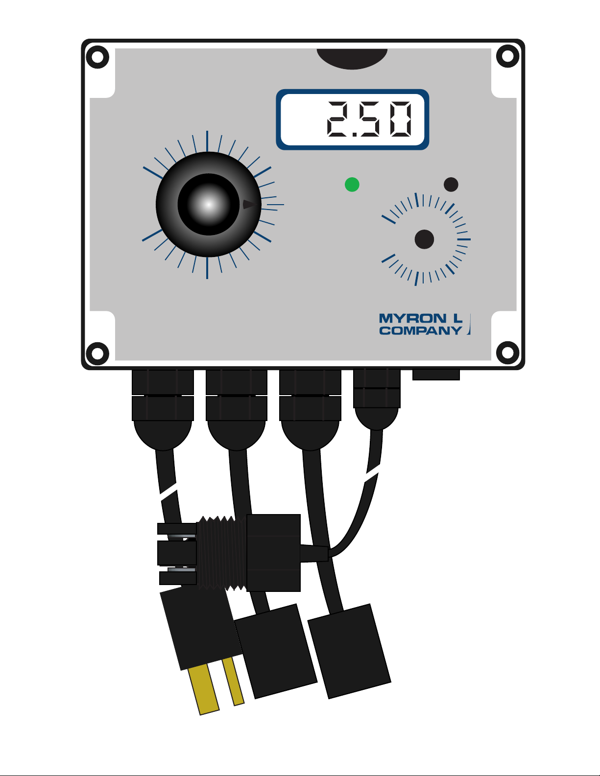
CTCII
w/ 3 1/2
Digit LCD
2
Page 7
60
80
100
120
0
1000
2000
3000
4000
5000
40
20
0
MICROSIEMENS / CM
CTCII
EC
MINUTES
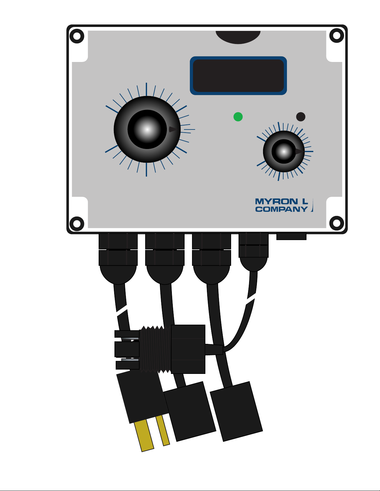
CTCII w/
Feed Pump
Limit Timer
3
Page 8

60
80
100
120
0
1000
2000
3000
4000
5000
40
20
0
MICROSIEMENS / CM
CTCII
EC
MINUTES
CTCII
w/ 3 1/2
Digit LCD
Feed Pump Limit Timer
4
Page 9

TABLE OF CONTENTS
SECTION PAGE
CTC Series II ILLUSTRATIONS (CTCII, CTCIID, CTCIIT & CTCIITD)......................................................................1-4
I. INTRODUCTION .................................................................................................................................................................. 7
A. SCOPE................................................................................................................................................................... 7
1. Functional Descriptions ........................................................................................................................... 7
2. Applications.............................................................................................................................................. 7
B. SPECIFICATIONS.................................................................................................................................................. 7
C. OPTIONAL FEATURES..........................................................................................................................................8
D. ACCESSORIES...................................................................................................................................................... 8
E. SENSORS .............................................................................................................................................................. 9
1. Conductivity/TDS ..................................................................................................................................... 9
2. Sensor Specications ..............................................................................................................................9
F. ORDER INFORMATION......................................................................................................................................... 9
1. How to order a CTCII controller .............................................................................................................. 9
2. How to order Sensors .............................................................................................................................. 9
II. INSTALLATION ....................................................................................................................................................................10
A. GENERAL............................................................................................................................................................... 10
B. MECHANICAL INSTALLATION .............................................................................................................................. 10
1. Surface Mounting..................................................................................................................................... 10
C. SENSOR INSERTION / DIP MOUNT ASSEMBLIES ............................................................................................. 11
1. CSAR Insertion Mode Assembly.............................................................................................................. 11
2. CS51R Alternate Dip Sensor Assembly ................................................................................................... 11
D. ELECTRICAL INSTALLATION................................................................................................................................ 11
1. 115/230 VAC Conversion......................................................................................................................... 11
2. Connecting the Sensor Cable.................................................................................................................. 12
a. Modication for US Pharmaceutical 25 (No Temperature Compensation) ......................................... 12
3. Flow Switch.............................................................................................................................................. 12
E. 0-10 VDC OUTPUT ................................................................................................................................................ 13
1. Connection............................................................................................................................................... 13
2. Voltage Divider......................................................................................................................................... 13
F. RESCALE............................................................................................................................................................... 14
III. OPTIONS & ACCESSORIES INSTALLATION.................................................................................................................... 15
A. -LTM (LIMIT TIMER MODULE) ............................................................................................................................. 15
1. Description............................................................................................................................................... 15
2. Installation................................................................................................................................................ 15
a. Hysteresis.......................................................................................................................................................... 15
B. -C4A MODULE (4-20mA OPTION) ........................................................................................................................ 15
1. Description............................................................................................................................................... 15
2. Installation................................................................................................................................................ 16
3. Recalibration............................................................................................................................................ 17
IV. OPERATING PROCEDURES .............................................................................................................................................. 18
A. FRONT PANEL INDICATORS & CONTROLS ....................................................................................................... 18
1. Red LED Indicator ................................................................................................................................... 18
2. Green LED Indicator ................................................................................................................................ 18
3. Set Point Control...................................................................................................................................... 18
4. Digital Display Models.............................................................................................................................. 18
5. Limit Timer Models................................................................................................................................... 18
B. SETUP PROCEDURES......................................................................................................................................... 19
1. Check-Out Procedure .............................................................................................................................. 19
2. Set Point Adjustment ............................................................................................................................... 19
3. Hysteresis (Dead Band) Adjustment........................................................................................................ 19
4. Feed Pump Limit Timer............................................................................................................................ 19
V. COMPONENT IDENTIFICATION, CALIBRATION AND PREVENTIVE CARE...................................................................20
A. PRIMARY COMPONENT IDENTIFICATION ......................................................................................................... 20
B. CALIBRATION PROCEDURES - MAIN CIRCUIT BOARD.................................................................................... 21
1. Electronic Calibration (Circuit Only)......................................................................................................... 21
2. Calibration Using Standard Solution........................................................................................................ 21
3. Transfer Standard Method....................................................................................................................... 22
C. PREVENTIVE CARE.............................................................................................................................................. 22
5
Page 10

TABLE OF CONTENTS Continued
SECTION PAGE
VI. OPTIONS & ACCESSORIES............................................................................................................................................... 23
A. OPTIONS ORDERED WITH CTCII....................................................................................................................... 23
B. OPTIONS & ACCESSORIES ORDERED SEPARATELY ......................................................................................23
C. STANDARD SOLUTIONS...................................................................................................................................... 24
VII. REPLACEMENT PARTS ..................................................................................................................................................... 25
VIII. WARRANTY......................................................................................................................................................................... 26
IX. GLOSSARY.......................................................................................................................................................................... 27
X. NOTES ................................................................................................................................................................................. 28
XI. ADDENDUM......................................................................................................................................................................... 29
A. CONDUCTIVITY, TDS AND TEMPERATURE RELATIONSHIPS.......................................................................... 29
6
Page 11

I. INTRODUCTION
Thank you for selecting one of the Myron L Company’s latest
Chemical Treatment Controllers. The CTCII is based on input
from ‘you’ - our customers, time proven designs, and many years
of instrumentation experience.
Since 1957, the Myron L Company has been providing customers
with quality products at an affordable price by designing and
producing products that are Accurate, Reliable, and Simple to use.
Quality you have come to rely and depend on.
As you read through this operation manual you will see the CTCII
is truly designed to be user friendly and simple to install.
The CTCII is packaged as a complete set ready to install which
includes the sensor, input power cord (115VAC) and two (2)
output connectors (115VAC) in a fully waterproof enclosure.
A. SCOPE
This operation manual provides the user with the necessary
information to install, operate and maintain your
Myron L Company CTCII Chemical Treatment Controller.
Section I. Provides Descriptions, Applications, Specications.
Section II. Installation; mounting, wiring and set up.
Section III. Options and Accessory installation procedures.
Section IV. Operating procedures.
Section V. Identies their primary components and provides the
user with easy-to-use calibration and preventive care
procedures.
Section VI. Options & Accessories List.
Section VII. Replacement Components.
Section VIII. Warranty information.
Section IX. Glossary, denitions.
Section X. Notes.
Section XI. Addendum.
1. FUNCTIONAL DESCRIPTIONS
All models feature a water proof & corrosion resistant IP65/NEMA
4X enclosure for bench or surface mounting. The CTCII is a
compact 4.7” (120mm) x 6.3” (160mm).
Bright dual GREEN/RED LED indicates ON/OFF (above or below
set point). All models feature TWO heavy-duty 10 amp output
relays, operating on increasing concentrations.
All models include input power cord* (115 VAC powercord 8 ft.
with USA 3 prong plug - NOT for use with 230 VAC), two (2)
output power connectors, CSAR sensor, and appropriate strain
reliefs.
LED. A 120 minute Limit Timer is provided to stop the feed pump
from continuing to pump chemical(s) in to tower, tank or system. A
bright YELLOW LED indicates when Limit Timer is on.
Model CTCIID Chemical Treatment Controller
0-5000 µS(µM) / ppm TDS 442™ Monitor/controller (value
displayed as X.XX mS(mM) or ppt w/ standard LCD). Front panel
is equipped with a “SET POINT” control, RED/GREEN indicator
LED, and a 3 1/2 digit liquid crystal display (LCD)*.
Model CTCIITD Chemical Treatment Controller
0-5000 µS(µM) / ppm TDS 442™ Monitor/controller (value
displayed as X.XX mS(mM) or ppt w/ standard LCD). Front panel
is equipped with a “SET POINT” control, RED/GREEN indicator
LED, and a 3 1/2 digit liquid crystal display (LCD)*. A 120 minute
Limit Timer is provided to stop the feed pump from continuing to
pump chemical(s) in to tower, tank or system. A bright YELLOW
LED indicates when Limit Timer is on.
* A 35BL (3 1/2 digit) backlit, or a 45BL (4 1/2 digit) backlit
display is available as an option for a full 0-5000 µS(µM) or ppm
displayed value.
2. APPLICATIONS
Chemical Treatment
Cooling Towers
Process Control
Wastewater Treatment
Food Processing
Plating
Power Plants
Laboratories
Printing
Boiler
Agriculture/Aquaculture
Are just a few of the applications
B. SPECIFICATIONS
RANGE:
0-5000 µS(µM) or ppm TDS 442™ (user selectable)
DISPLAY:
Models CTCIID & CTCIITD:
1/2” (13mm) 3 1/2 digit LCD
Displayed value — 0-5.00 mS(mM) or ppt.
NOTE: 3 1/2 digit LCD may be replaced with either a 3 1/2 or a 4
1/2 digit back lit LCD - available as options.
4 1/2 digit displayed value — 0-5000 µS(µM) or ppm.
The CS51R sensor for more demanding applications may be
substituted at an additional cost.
For specic CTCII congurations, reference the following
individual model descriptions.
*NOTE: for 230 VAC or other power requirements the plug must
be cut off or removed and hard wired directly to the source or a
local plug or adapter may be installed.
Model CTCII Chemical Treatment Controller
0-5000 µS(µM) / ppm TDS 442™ Controller. Front panel is
equipped with a “SET POINT” control and RED/GREEN indicator
LED.
Model CTCIIT Chemical Treatment Controller
0-5000 µS(µM) / ppm TDS 442™ Controller. Front panel is
equipped with a “SET POINT” control and RED/GREEN indicator
ACCURACY
All Models: ± 2 % of Full Scale
SENSITIVITY
0.05% of span
STABILITY
0.05% of span
7
Page 12

REPEATABILITY
0.1% of span
CALIBRATION CHECK
Built in Electronic Calibration (EC) Mid scale 2500/2.50.
RECORDER OUTPUT
0-10 VDC @ 5 mA max. (linear); standard on all models
OUTPUT IMPEDANCE
100Ω ±5%
SENSOR INPUT
1 (sensor included)
CONTROL FUNCTION
ALL Models:
Single set point alarm/control continuously adjustable
0-100% of span
Hysteresis
Adjustable from 0.3-6% of full scale
Indicators
“HIGH” (red) and “LOW” (green) set point LED.
Relay Contact Rating X 2
SPDT 10 amp @ 115 VAC, 30 VDC. Relay operates on
increasing reading.
Fused Outputs (2)
5 amp @ 115/230 VAC.
WEIGHT
CTCII: average 2 Ibs. (0.9 kg)
C. OPTIONAL FEATURES
-45 4 1/2 digit backlit liquid crystal display (LCD)
-35BL 3 1/2 digit backlit LCD
-24V 24 VAC isolated power supply (special order)
-24VD 24 VDC isolated power supply (special order)
-C4A 4-20 mA Output Module
-CS51R More Rugged Sensor (replaces the CSAR)
D. OPTIONS & ACCESSORIES
(ordered separately)
45O 4 1/2 digit backlit liquid crystal display (LCD)
35BLO 3 1/2 digit backlit LCD
C4AO 4-20 mA Output Module
LTMO Limit Timer Module Kit
442-3000 Calibration Solution (3000 ppm / 3900 µM/µS)
INPUT POWER SPECIFICATIONS
115/230 VAC ±15%, 50/60 Hz (User selectable) overvoltage
category II
100 mA Maximum Current
Double Insulated
Fuse - 100mA Slow Blow (T.10A) for both 115 & 230 VAC
(V~) User replaceable
Humidity - 20-90% non-condensing
Max. Altitude -
40,000 ft/12,000 meters non-operating
10,000 ft/3000 meters operating
Pollution degree 2
24 VAC Option available on Special Order
Overvoltage category II
250 mA Maximum Current
Double Insulated
Fuse - 250mA Slow Blow (T.25A) User replaceable
24 VDC Option available on Special Order
250 mA Maximum Current
Double Insulated
Fuse - 250mA Slow Blow (T.25A) User replaceable
AMBIENT TEMPERATURE RANGE
32°F ( 0°C) to 140°F (60°C)
DIMENSIONS
4.7” (120mm) H x 6.3” (160mm) W x 3.6” (92mm) D
HOUSING CONSTRUCTION
Fully gasketed heavy-duty ABS waterproof and corrosion
proof.
Rated IP65/NEMA 4X
Double Insulated
DOUBLE INSULATED
8
Page 13

E. SENSORS
1. CONDUCTIVITY/TDS
CTCII Conductivity/TDS Chemical Treatment Controllers come
standard with the CSAR. The CSAR is of one piece molded
construction with two 316 stainless steel pins (electrodes).
Standard 3/4” NPT installation. It is rated for applications that do
not exceed 75PSI@60°C.
Other sensors for more demanding applications maybe
substituted at an additional cost. All sensors include temperature
sensor for automatic temperature compensation.
The CS51R models compact size allows mounting in a standard
3/4” NPT tee. The sturdy polypropylene bushing is modular for
easy, inexpensive replacement. It is rated for applications that
do not exceed 100PSI@100°C. Add -CS51R to order number if
desired.
Special order High Temperature, High Pressure sensors.
For detailed descriptions of these and other sensors, see Sensor
Selection Guide and specic sensor data sheets available
from your local distributor, the Myron L Company, or on line at
www.myronl.com.
a. SENSOR SPECIFICATIONS
TEMPERATURE COMPENSATION
Automatic to 25°C, between 32-212°F (0-100°C)
except high temperature models - up to 205°C.
PRESSURE/TEMPERATURE LIMITS
CSAR - 75PSI (517.2 kPa) at 60°C (140°F)
CS51R - 100 psi (689.6 kPa) at 212°F (100°C)
For higher limits, see Special Order Models below.
FITTING/BUSHING
CSAR: 3/4” MNPT threaded ABS body
CS51R: Modular Polypropylene threaded 3/4” NPT
CS41HTR Cond/TDS High Temperature Model 250PSI@205°C
For additional information see sensor selection & specic data
sheets for details.
F. ORDERING INFORMATION
Follow steps 1, 2 & 3.
NOTE: CTCII model number includes the CSAR sensor as
standard. If other than the CSAR sensor is desired, please specify
when ordering.
1. HOW TO ORDER CTCII
Specify Model:
CTCII — Basic controller
CTCIID — w/ LCD
CTCIIT — w/ Limit Timer
CTCIITD — w/ Limit Timer and LCD
EXAMPLE A — a basic CTCII controller with a 4-20 mA output.
:
MODEL OPTION
CTCII — C4A
Written as — CTCII-C4A
EXAMPLE B -— a CTCIID controller with a 3 1/2 digit digital
display, a 4-20 mA output, and a CS51R sensor. The CS51R
sensor is for more demanding applications at a modest price
increase.
MODEL OPTION
CTCIID — C4A — CS51R
Written as — CTCIID-C4A-CS51R
2. HOW TO ORDER SPECIAL SENSOR
or Sensor Options
Select Special sensor and/or add options to sensor as in
examples below.
CABLE
Shielded; 10’ (3 meters) standard.
25’ (7 meters), and
100’ (30 meters) lengths also available.
DIMENSIONS
CSAR: 3/4 MNPT. Electrodes, Twin Pin ~3/4 (20mm) L.
CS51R: 3/4 MNPT. Electrode 1.2” (30mm) L; 0.5”
(13mm) Dia.
For additional information see sensor selection & specic data
sheets for details.
b. SENSOR OPTIONS
-25 25’ Shielded Cable
-100 100’ Shielded Cable
CS51R Only
-T Titanium - in place of Stainless Steel
-STF Sanitec Fitting.
1/2” thru 4”. State size, i.e. STF-1/2.
-PV 1/2” PVDF tting.
{replaces polypropylene}
-HPSS 1/2” 316 STAINLESS STEEL tting
(replaces polypropylene).
c. SPECIAL ORDER MODELS — 316 Stainless Steel
(1.0 cell constant)
CS40R Conductivity/TDS Valve Insertable 100PSI@150°C
CS40HTR Above High Temperature Model 250PSI@205°C
CS41R Cond/TDS High Temperature Model 100PSI@150°C
EXAMPLE C — a model CS51R sensor made with Titanium and a
100 foot cable.
MODEL OPTIONS
-CS51R — T-100
Written as — CS51R-T-100
EXAMPLE D — a Special Order High Temperature sensor made
of Titanium, and a Wet-Tap Valve.
MODEL OPTIONS
-CS40HTR — T-WTV
Written as — -CS40R-T-WTV
3. COMBINING CTCII and SPECIAL SENSOR
Add Steps 1 & 2.
EXAMPLE — Add above examples B and C. A CTCIID controller
with a 3 1/2 digit digital display, a 4-20 mA output, and a CS51R
sensor made with Titanium and a 100 foot cable.
Written as — CTCIID-C4A-CS51R-T-100
9
Page 14

II. INSTALLATION
SURFACE MOUNTING DIAGRAMS
DIMENSIONS IN INCHES
(MILLIMETERS)
Figure II.B.1.
5.83"
(148mm)
3.54"
(90mm)
A. GENERAL
This section provides the recommended procedures for properly
installing your CTC Series II Chemical Treatment Controller, and
sensors.
CAUTION - READ FOLLOWING CAREFULLY
!
WARNING: THE MYRON L COMPANY RECOMMENDS THAT
ALL MOUNTING AND ELECTRICAL INSTALLATIONS BE
PERFORMED BY QUALIFIED PERSONNEL ONLY. FAILURE
TO DO SO COULD CAUSE DAMAGE TO INSTRUMENT, AND
COULD BE HARMFUL OR FATAL TO PERSONNEL.
B. MECHANICAL INSTALLATION
All CTCII electronics are packaged inside a waterproof/weatherproof enclosure.
The enclosure is designed for surface mounting.
There are four basic guidelines to consider when selecting a
mounting location:
1. Select a site that limits the CTCII exposure to excessive
moisture and corrosive fumes (water owing or dripping
directly on the power cords may cause an unsafe
condition, and is NOT recommended).
2. For best results, position your CTCII controller and
sensor as close as possible to the point being controlled.
The CTCII controllers are not designed to operate with a
sensor cable length that exceeds 100’ (30 meters).
3. Mount your CTCII controller at eye level for viewing
convenience.
1. SURFACE MOUNTING
NOTE: Due to the many variables of installations mounting
screws are not supplied. It is recommended that suitable #6 (M4)
screws for the exact conditions be used, i.e. woodscrews, metal
or sheetmetal.
1. Select mounting site location.
2. Mark and drill the required mounting holes. For hole
drilling locations, see gure II.B.1.
3. Hold the CTCII in place while starting and tightening the
mounting screws.
DOUBLE INSULATED
10
Page 15
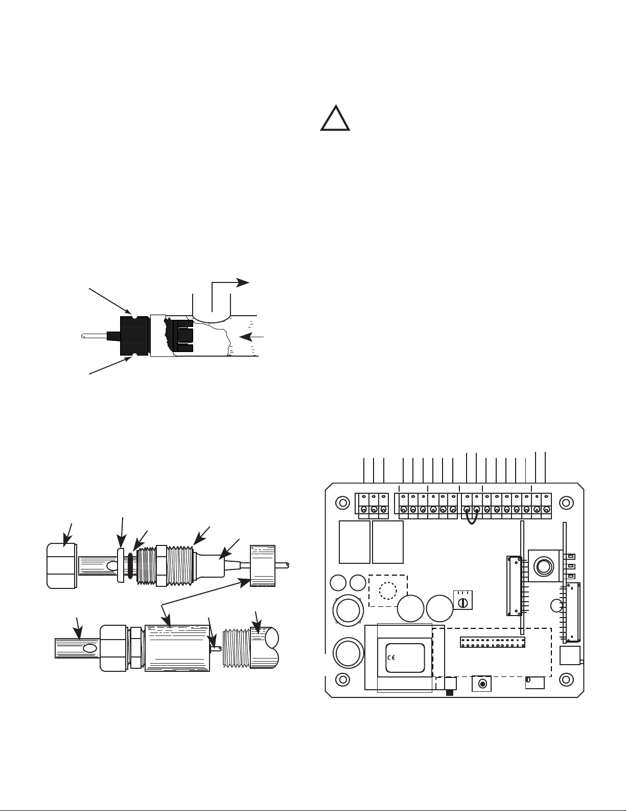
C. SENSOR INSERTION/IMMERSION MOUNTING
CSAR INSERTION MODE
Figure II.D.1
OUT
IN
DOT
DOT
CABLE
SENSOR TIP
COUPLING
3/4" NPT
EXTENSION TUBE
SECURING NUT
PLASTIC
WASHER
O-RING
THREADED FITTING
3/4" FNPT
FLANGE
FUSE
ELECTRICAL CONNECT DIAGRAM
Figure II.E.1
DIS
TRANSFORMER
DISPLAY
Yel
FEED
PUMP
BLEED
VALVE
POWER
FLOW
SWITCH
SENSOR 0-10VDC
C4AM
LTM
HYST
CAL
PWR C GDPWR C GDPWR C GD FS BK WT RD GN NU R- R+
Flow Switch
Jumper Remove if
flow switch
installed.
TDS COND
MYRON L
COMPANY
CTCII
BLK
WHT
RED
GRN
NEU
R-
R+
POWER
COMM
GROUND
POWER
COMM
GROUND
POWER
COMM
GROUND
INPUT POWER SENSOR
FEED
PUMP
BLEED
VALVE
FLOW
SWITCH
0-10 VDC
EC
SWITCH
BLEED FEED
CAP
CAP
RELAY
RELAY
115/230 VAC
SELECT SWITCH
The Sensor’s mounting orientation must provide a continuous and
adequate circulation ow to prevent the trapping of air bubbles
within the Sensor’s electrode area (CSAR shown in gure II.D.1).
Failure to do so will result in conditions that may prevent the
Sensor from functioning properly. The CSAR sensor is designed
for insertion (in-line installation). The optional CS51R sensor may
be ordered and installed as either insertion, or immersion (see
gure II.D.2).
1. INSERTION MODE (in-line installation)
Use approved sealant, i.e. Teon tape as required.
1. Pre-wind CSAR sensor before installation. Rotate sensor
counter clockwise (CCW) (as if removing sensor) 4-5
turns before installing into tting.
2. Insert the Sensor Fitting assembly into the “T” tting with
electrode aligned with direction of ow as shown in gure
II.D.1. and tightly secure. Note: The CS51R installs in
the same manner. (but does not require any turns)
D. ELECTRICAL INSTALLATION
As shipped from the factory, the input power cable, the two
(2) output connectors, and the sensor are pre-wired to the
controller. Electrical connection simply requires plugging in
the appropriate valve and pump, and input power as labeled.
WARNING !
!
A device to disconnect the Model CTCII from the power
supply is required. It is recommended that this switch or
circuit breaker be labeled as the disconnection device for the
Model CTCII.
WARNING: All CTCII controllers are factory set for 115 VAC.
Before starting, ensure the input power “115/230” selection
is correct for your requirements. Failure to do so is beyond
the responsibility of the Myron L Company. See section II.D.1.
below and gure II.E.1.
NOTE: Some models, if ordered, have either a 24 VAC or a 24
VDC input power requirement - check labels carefully.
The following instructions are if the input power, output power or
sensor cables are removed.
The electrical installation procedures provided in this manual are
common to all CTCII controllers. Unless otherwise instructed,
refer to gure II.E.1. for the CTCII controller’s terminal block
connector wiring designations.
Use approved sealant, i.e. Teon tape as required.
2. IMMERSION OR DIP SENSOR ASSEMBLY
1. Verify that the CS51R Sensor’s Fitting assembly is
properly assembled as shown in gure II.D.2.
2. Insert and pull the Sensor’s cable through the extension
tube and then tightly attach extension tube to Sensor
assembly as shown in gure II.D.2.
IMMERSION OR DIP CS51R SENSOR
ASSEMBLY SHOWN
Figure II.D.2
11
Page 16
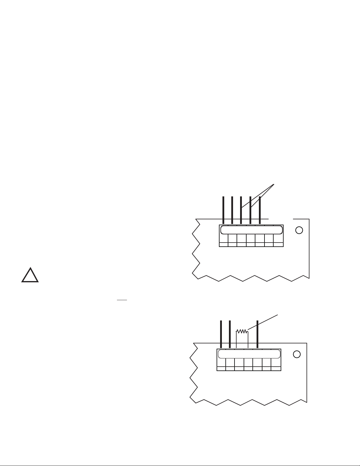
1. 115/230 VAC CONVERSION
INSTALL 1.1K�
RESISTOR HERE
BK WT RD GN NU R- R+
SENSOR LEADS
Main CB Assembly
Figure II.E.3
Main CB Assembly
Figure II.E.2
SENSOR LEADS
REMOVE THESE TWO LEADS
BK WT RD GN NU R- R+
0-10VDC
OUTPUT
1. Before turning power on to the CTCII controller ensure
the proper input voltage has been selected. Failure to
do so will blow the fuse. It could, under some conditions,
cause injury and damage the instrument voiding the
warranty.
2. Locate switch located next to the fuse holder.
3. Using a screwdriver, turn switch to required voltage.
2. CONNECTING THE SENSOR CABLE
If the sensor has been removed or requires replacement for any
reason.
1. Place the Sensor’s interface cable through the supplied
watertight cable restraint into the enclosure’s appropriate
access hole.
2. Install the sensor cable wire to comply with local
electrical codes*. Follow the color code as marked. See
gure II.E.1.
a. MODIFICATION FOR US PHARMACEUTICAL 25
(No Temperature Compensation)
This simple modication will allow your CTCII Chemical
Treatment Controller to meet USP 25 requirements by defeating
the normal temperature compensation circuit thus giving
“uncompensated” readings as required. Rarely will this be
required in the normal applications of this type of controller.
However, if it becomes necessary, the following will step you
through it.
5. If sensor is installed, locate and remove the RED (RD)
and the GREEN (GN) leads from MAIN Circuit Board, as
shown in gure II.E.2.
6. Cut off or tape RED (RD) and the GREEN (GN) leads
from sensor.
7. Install 1.1kΩ resistor at RED (RD) and the GREEN (GN)
connector locations, as shown in gure II.E.3.
8. Carefully reinstall the front panel.
9. Reinstall the clear cover
10. Reinstall the four (4) screws and tighten.
11. To operate, turn power ON.
NOTE: Recalibration will require both the solution and sensor be
at 25°C for maximum accuracy.
3. FLOW SWITCH
A ow switch may be installed (electrically connected) utilizing the
FS connection*, see gure II.E.1, remove jumper and connect ow
switch leads to terminals.
*CAUTION: The connectors require only a small screwdriver or
a pen to push on the release levers. The release levers may be
broken or damaged if not pushed straight toward the circuit board.
DO NOT push the release levers sideways.
Specications:
As required to meet USP 25.
Installation
Briey A resistor is installed in place of the sensor “temperature” sensing
leads.
The extra sensor leads are either cut off or the ends are wrapped
in tape to prevent shorting.
CAUTION - READ FOLLOWING CAREFULLY
!
WARNING: BEFORE STARTING, IF CTCII CONTROLLER IS
INSTALLED, ENSURE THE POWER IS OFF. FAILURE TO DO
SO COULD CAUSE DAMAGE TO THE INSTRUMENT, AND
COULD BE HARMFUL OR FATAL TO PERSONNEL. ONLY
QUALIFIED PERSONNEL SHOULD INSTALL OR SERVICE
ELECTRICAL EQUIPMENT.
Requirements:
One 1.1kΩ .1% resistor, user supplied or may be ordered from the
Myron L Company.
NOTE: When opening instrument, remove front panel with care.
1. Using a Phillips Head screwdriver remove the four (4)
screws on the clear cover.
2. Remove clear cover.
3. The front panel is held in place with hook & loop strips
on each side. By carefully lifting at the slot on the top,
the front panel will pull toward you. Do not pull more than
about 8 inches/20CM.
DO NOT pull on control knob(s).
4. Rotate the front panel down so that the back side is
facing you. The Circuit Board is mounted to the back of
the front panel.
12
Page 17
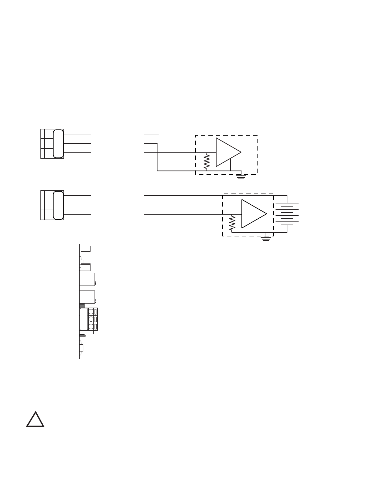
E. 0-10 VDC RECORDER OUTPUT
Figure II.F.1
0-10V Output
+
-
A
B
+
-
Recording
Device
Figure II.F.2
BK WT RD GN NU R- R+
SENSOR LEADS
Main CB Assembly
0-10VDC
OUTPUT
- +
NEW
OUTPUT
AS
SELECTED
The 0-10 VDC output is designed to give the user the capability
of sending a signal to a remote meter, recorder, PLC or SCADA
system.
Requirements
A hole of the proper size must be drilled in the enclosure. The
user/installer must choose a location that will NOT interfere with
normal operation. To ensure waterproof integrity, a watertight
cable restraint must be used. Failure to do so or improper
installation will void the warranty and may be costly to repair.
1. CONNECTION
1. Drill appropriate size hole.
2. Place the user supplied interface cable and watertight
cable restraint into the hole.
3. Connect the Recorder’s plus (+) and minus (-) terminal
wires to the Recorder output connectors. (See gure
II.E.2.)
4. Refer to Section V.B.1.b for the procedures to calibrate
the 0-10 VDC voltage output.
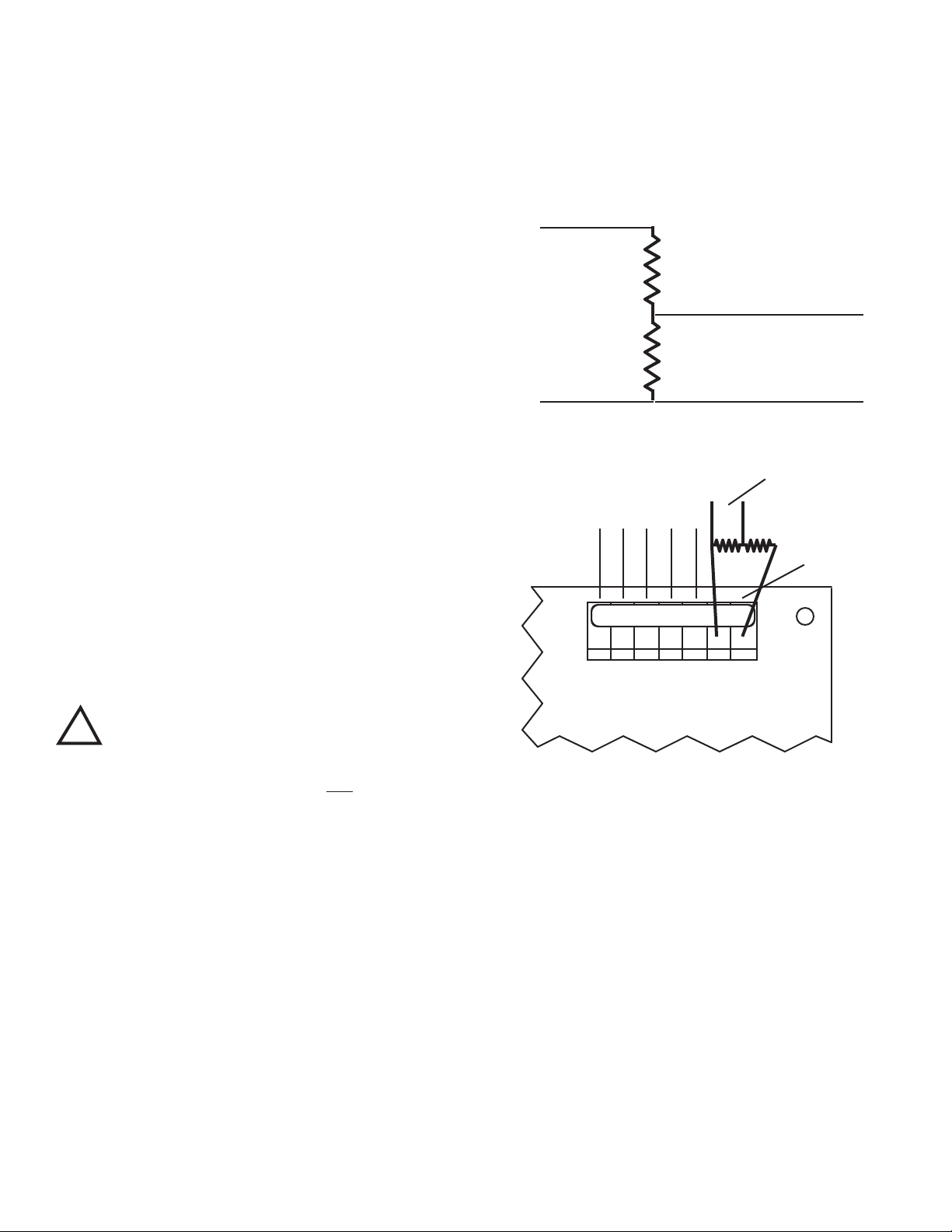
2. VOLTAGE DIVIDER
A voltage divider gives the user the ability to scale or tailor the
output to a particular need or requirement due to the input of
another device, i.e. the output of the Main CB is 0-10V while the
input requirement of a particular recording device is 0-5V.
6. Attach leads to recording device as shown in gure II.F.1.
7. Attach resistors to 0-10V Output as shown in gure II.F.2.
Ensure resistors and leads DO NOT short to each other
or to any part of the CB assembly.
8. Recalibration is required, see Calibration Procedures,
section V.B.
Briey—
Two resistors are installed across the 0-10V output.
The output is recalibrated to required voltage.
Requirements
Select two (2) resistors as listed;
For 0-5V Output both “A & B” are 2K Resistors.
For 0-1V Output “A” is a 9K resistor and “B” is a 1K resistor.
!
WARNING: BEFORE STARTING, IF MONITOR/CONTROLLER
IS INSTALLED, ENSURE THE POWER IS OFF. FAILURE TO
DO SO COULD CAUSE DAMAGE TO THE INSTRUMENT, AND
COULD BE HARMFUL OR FATAL TO PERSONNEL. ONLY
QUALIFIED PERSONNEL SHOULD INSTALL ELECTRICAL
EQUIPMENT.
Physical
If the front panel has all ready been removed from the enclosure
skip to #3.
1. Using a Phillips Head screwdriver remove the four (4)
2. Remove clear cover.
3. The front panel is held in place with hook & loop strips
4. Rotate the front panel down so that the back side is
5. Solder two selected resistors together as shown in gure
a. INSTALLATION
CAUTION - READ FOLLOWING CAREFULLY
screws on the clear cover.
on each side. By carefully lifting at the slot on the top,
the front panel will pull toward you. Do not pull more than
about 8 inches/20CM.
DO NOT pull on control knob(s).
facing you. The Circuit Board is mounted to the back of
the front panel.
II.F.1.
Reassembly
1. Carefully reinstall the front panel, ensure no wires have
been pinched.
2. Reinstall the clear cover.
3. Reinstall the four (4) screws and tighten.
4. If desired, install corner covers.
5. To operate, turn power ON.
13
Page 18
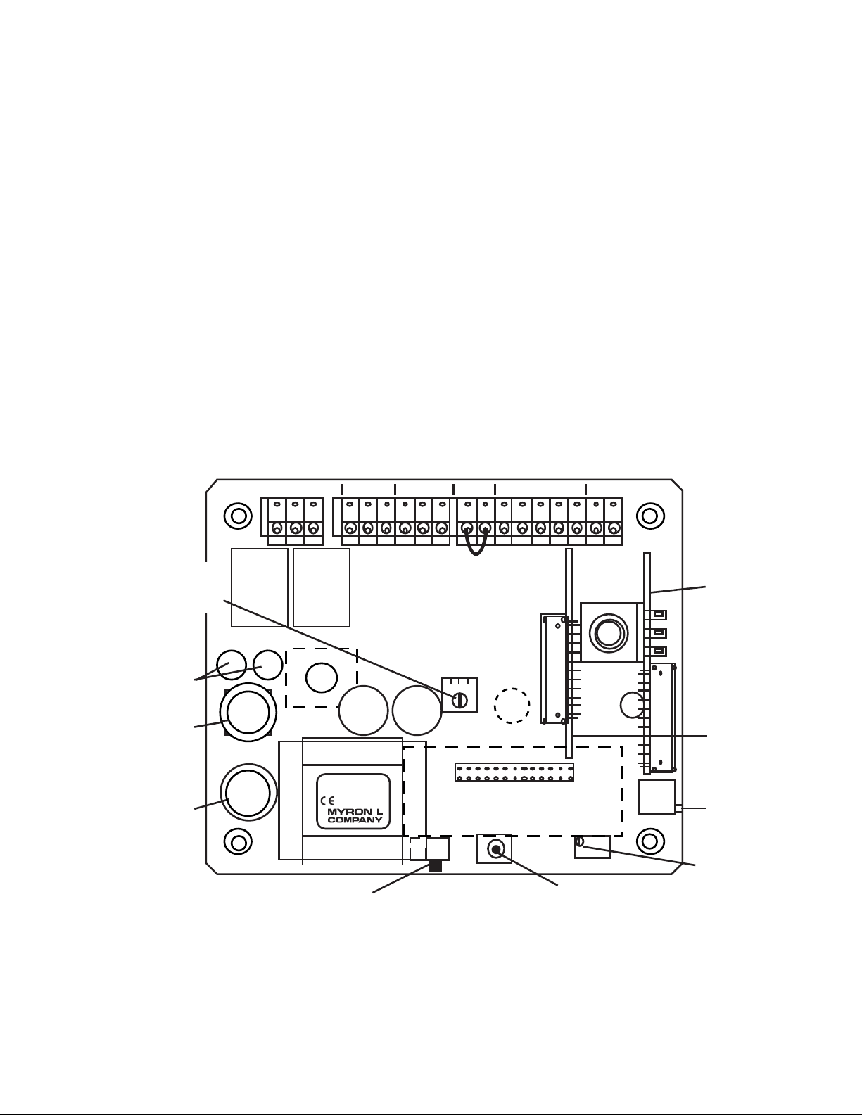
F. RE-SCALE YOUR CTCII CONTROLLER
Main CB Assembly
Figure II.F.1
SET POINT
HYSTERESIS
RIGHT INC
LEFT DEC
115/230 VAC
SELECT SWITCH
100mA Slow Blow (T.10A)
115 & 230 VAC (V~)
SCALE SELECT
ELECTRONIC
CALIBRATION
MAIN
CALIBRATION
CONTROL
DISPLAY
CALIBRATION
CONTROL
(FACTORY SET)
OPTIONAL
LIMIT
TIMER
CONTROL
MODULE
OPTIONAL
4-20 mA
OUTPUT
MODULE
DIS
CAL
TDS COND
EC
CTCII
DISPLAY
TRANSFORMER
Yel
CAP CAP
C4AM
LTM
HYST
Flow Switch
Jumper Remove if
flow switch
installed.
SWITCH
FUSE
RELAY RELAY
BLEED FEED
FEED
PUMP
BLEED
VALVE
POWER
FLOW
SWITCH
SENSOR 0-10VDC
FS BK WTRD GN NU R- R+PWR C GDPWR C GDPWR C GD
Wickman Fuse 5 Amp
(#3741500041 or equiv)
115 VAC(V~)
1. DESCRIPTION
The CTC Series II controller, has been designed for easy eld rescaleability. To re-scale your 0-5000 µS CTCII to 0-5000 “PPM”
TDS 442™ or visa versa requires the simple slide of a switch.
CAUTION - READ FOLLOWING CAREFULLY
!
WARNING: BEFORE STARTING, IF MONITOR/CONTROLLER
IS INSTALLED, ENSURE THE POWER IS OFF. FAILURE TO
DO SO COULD CAUSE DAMAGE TO THE INSTRUMENT, AND
COULD BE HARMFUL OR FATAL TO PERSONNEL. ONLY
QUALIFIED PERSONNEL SHOULD INSTALL OR SERVICE
ELECTRICAL EQUIPMENT.
Physical
NOTE: When opening instrument, remove front panel with care. If
the front panel has already been removed from the enclosure skip
to #3.
1. Using a Phillips Head screwdriver remove the four (4)
screws on the clear cover.
2. Remove clear cover.
3. The front panel is held in place with hook & loop strips
on each side. By carefully lifting at the slot on the top,
the front panel will pull toward you. Do not pull more than
about 8 inches/20CM.
DO NOT pull on control knob(s).
4. Rotate the front panel down so that the back side is
facing you. The Circuit Board is mounted to the back of
the front panel.
5. Locate the switch next to the transformer. See gure
II.F.1.
6. Slide knob toward the desired scale - TDS/ppm or
COND/µM(µS).
7. Recalibrate, see CALIBRATION PROCEDURES, section
V.B.
8. Install (remove) Parts Per Million - TDS label (supplied
inside).
9. Reassemble front panel.
14
Page 19
III. OPTIONS &
ACCESSORIES
A. LIMIT TIMER MODULE OPTION
LTMO Limit Timer Module Kit ordered separately.
1. DESCRIPTION
This module allows the user to set a “limit” of up to 120 minutes
on the length of time the feed pump will operate.
Specications:
Control Function:
Controls the Feed Pump Relay only.
2. INSTALLATION
Briey The Limit Timer Module simply plugs into the CTCII circuit board,
see gure III.B.4.
4. Rotate the front panel down so that the back side is
facing you. The Circuit Board is mounted to the back of
the front panel.
5. Carefully press the LT Limit Timer Module into the Circuit
Board as shown in gure III.A.4.
When fully seated the LTMO option will snap into place.
6. Reassemble front panel.
7. Turn shaft fully counter-clockwise.
8. Install knob on shaft and align to “DOT”.
9. Reinstall clear cover.
B. C4A MODULE
(4-20 mA OPTION)
-C4A 4-20 mA Self/Remote-powered Isolated output module
ordered with controller.
C4AO 4-20 mA Self/Remote-powered Isolated output module
ordered separately.
1. DESCRIPTION
The 4-20 mA option gives the CTCII controller the ability to
send a signal very long distances with minimal interferences and
signal degradation. The output is an Isolated 4-20 mA signal that
corresponds to the full scale range of the controller into which it is
installed. This output is easily congured to be either self-powered
or remote-powered as required for your particular application.
Figure III.A.1
CAUTION - READ FOLLOWING CAREFULLY
!
WARNING: BEFORE STARTING, IF MONITOR/CONTROLLER
IS INSTALLED, ENSURE THE POWER IS OFF. FAILURE TO
DO SO COULD CAUSE DAMAGE TO THE INSTRUMENT, AND
COULD BE HARMFUL OR FATAL TO PERSONNEL. ONLY
QUALIFIED PERSONNEL SHOULD INSTALL OR SERVICE
ELECTRICAL EQUIPMENT.
Physical
NOTE: When opening instrument, remove front panel with care. If
the front panel has already been removed from the enclosure skip
to #3.
1. Using a Phillips Head screwdriver remove the four (4)
screws on the clear cover.
2. Remove clear cover.
3. The front panel is held in place with hook & loop strips
on each side. By carefully lifting at the slot on the top,
the front panel will pull toward you. Do not pull more than
about 8 inches/20CM.
DO NOT pull on control knob(s).
NOTE: The maximum impedance of the user’s current input
instrument should not exceed 600 ohms.
Since the output is an isolated current loop, it is the ideal choice
for applications requiring; a control signal to be run very long
distances, systems requiring a 4-20mA input or in instances where
isolation is necessary.
As the output is isolated, and a current, it is useful for long
distance interface, especially where wiring resistances may be
high, and/or the ground potentials may differ between the sensor
input ground and the current receiving instruments ground.
The 4-20 mA output will not be degraded in accuracy even
when the ground differences are as much as 120 VAC @ 60Hz.
Interface wire resistance of 350Ω will not degrade the accuracy of
the output when interfaced to a typical 250Ω input impedance of a
transmitter current input device.
The output is capable of driving a minimum of 600Ω worse case,
therefore, will satisfy virtually all modern interface requirements.
Current input devices usually have an input impedance of 250Ω,
however, some older designs can have as high as 500Ω or as
low as 10Ω. This “-C4A” option will drive any impedance from 0 to
600Ω without any degradation of performance.
There are two modes in which current loop transmitters operate;
Self-Powered and Remote-Powered.
Self-Powered — the transmitter provides the power to drive
the 4 to 20 mA current. See gure III.B.1.
Remote-powered — the receiving instrument provides the
power to drive the 4 to 20 mA current. See gure III.B.2.
15
Page 20
Specications
-
Figure III.B.1
(-)
CURRENT INPUT INSTRUMENT
Self - Powered
(+)
+
SIGNAL OUT(+)
POWER OUT
POWER IN
+
NC
-
CURRENT INPUT INSTRUMENT
Figure III.B.2
Remote - Powered
(+)
(-)
+
NC
+ 35 VDC
MAXIMUM
(+)
+
SIGNAL OUT
POWER IN
POWER OUT
SO PO PI
SO PO PI
PO
SO PI
POT1
D1
POT2
U4
R3
Self-Powered and Remote-Powered
Drive Impedance — 0 to 600Ω
Common Mode Maximum — 120 VAC @ 60 Hz
Isolation — 100pf max. to Model 750II circuit common
100pf max. to input power line
Calibration
Two multi-turn pots — Factory Set.
4mA = Zero (0)
20mA = 12 mA - Mid Scale
Calibration is NOT required. However, if you feel you must verify
or recalibrate, see RECALIBRATION.
DO SO COULD CAUSE DAMAGE TO THE INSTRUMENT, AND
COULD BE HARMFUL OR FATAL TO PERSONNEL. ONLY
QUALIFIED PERSONNEL SHOULD INSTALL OR SERVICE
ELECTRICAL EQUIPMENT.
Physical
1. Using a Phillips Head screwdriver remove the four (4)
screws on the clear cover.
2. Remove clear cover.
3. The front panel is held in place with hook & loop strips
on each side. By carefully lifting at the slot on the top,
the front panel will pull toward you. Do not pull more than
about 8 inches/20CM.
DO NOT pull on control knob(s).
Figure III.B.3
Briey The C4A Module simply plugs into the CTCII circuit board, see
Figure III.B.4. Connect signal wires per gure III.B.1 or III.B.2.
2. INSTALLATION
!
WARNING: BEFORE STARTING, IF MONITOR/CONTROLLER
IS INSTALLED, ENSURE THE POWER IS OFF. FAILURE TO
16
CAUTION - READ FOLLOWING CAREFULLY
4. Rotate the front panel down so that the back side is
facing you. The Circuit Board is mounted to the back of
the front panel.
5. Locate the connector on the Circuit Board labeled C4AM.
6. Align as shown.
7. Press into place. The module will click when fully seated.
Electrical
1. Connect the signal and power wires as required, as
shown in gures III.B.1. & III.B.2. This assumes you have
already connected the other end of the wires as required.
a. Place the remote interface cable and user supplied
watertight cable restraint into the enclosure’s
appropriate access hole.
b. Neatly connect the signal cable wires to the CTC’s
appropriate connectors as shown in gure III.B.3.
2. To test, turn power ON.
3. Press the EC switch and monitor the output at your
remote site, or with a DVM set to DC milliamps. Attach
the DVM to the output connectors per your requirements,
i.e. self-powered or remote-powered, see gures III.B.1.
& III.B. 2. If the C4A module is connected properly it will
indicate 12mA.
4. Turn power OFF.
5. Carefully reinstall the front panel.
6. Reinstall the clear cover
7. Reinstall the four (4) screws and tighten.
8. To operate, turn power ON.
Page 21
-
+
POWER IN
NC
+
Remote
Power
Supply
(+)
(-)
(+) SIGNAL OUT
POWER OUT
POWER IN
+
-
(+)
(-)
(+) SIGNAL OUT
POWER OUT
Figure III.B.5.
Remote - Powered
NC
Self - Powered
+
-
+
SO PO PI
SO PO PI
DVM
DVM
MYRON L
COMPANY
Flow Switch
Jumper Remove if
flow switch
installed.
C4AM
LTM
ELECTRONIC
CALIBRATION
DIS
Figure III.B.4.
SCALE SELECT
SET POINT
HYSTERESIS
RIGHT INC
LEFT DEC
115/230 VAC
SELECT SWITCH
100mA Slow Blow (T.10A)
115 & 230 VAC (V~)
SWITCH
FUSE
RELAY RELAY
CAP CAP
HYST
BLEED
BLEED
VALVE
POWER
FEED
PUMP
FLOW
SWITCH
SENSOR 0-10VDC
PWR C GDPWR C GDPWR C GD FS BK WTRD GN NU R- R+
DISPLAY
Yel
CAL
MAIN
CALIBRATION
CONTROL
DISPLAY
CALIBRATION
CONTROL
(FACTORY SET)
OPTIONAL
LIMIT
TIMER
CONTROL
MODULE
OPTIONAL
4-20 mA
OUTPUT
MODULE
TDS COND
CTCII
EC
FEED
TRANSFORMER
Wickman Fuse 5 Amp
(#3741500041 or equiv)
115 VAC(V~)
The 4-20 Module was calibrated at the factory, however, if you
wish to check the calibration the following procedure will help you
to accomplish this task. Exercise caution while performing this
procedure.
Requirements; a DVM set to DC milliamps, a tweaker or small
standard slot screwdriver.
This procedure assumes the front panel is removed.
3. RECALIBRATION
1. If sensor is connected, disconnect sensor wires from
sensor terminal block.
2. Attach the DVM to the output connectors per your
requirements, i.e. self-powered or remote-powered, see
gure III.B.5.
3. Turn power ON, with the display (if included) at ZERO or
ZERO DC volts out at Recorder, the DVM should indicate
4 mA at the signal out.
4. If not, adjust the CAL control marked “4mA” until the
DVM indicates 4 mA, see gure III.B.3.
5. Press the EC switch, the DVM should indicate 12 mA.
6. If not, adjust the CAL control marked “20mA” until the
DVM indicates 12 mA. See gure III.B.3.
NOTE: The C4A is linear, calibration at mid scale will not effect the
7. Calibration is complete.
8. Turn power OFF.
9. Reinstall the clear cover
10. Reinstall the four (4) screws and tighten.
11. To operate, turn power ON.
accuracy.
17
Page 22
IV. OPERATING PROCEDURES
60
80
100
120
0
1000
2000
3000
4000
5000
40
20
0
MICROSIEMENS / CM
CTCII
EC
MINUTES
60
80
100
120
0
1000
2000
3000
4000
5000
40
20
0
MICROSIEMENS / CM
CTCII
EC
MINUTES
60
80
100
120
0
1000
2000
3000
4000
5000
40
20
0
MICROSIEMENS / CM
CTCII
EC
MINUTES
60
80
100
120
0
1000
2000
3000
4000
5000
40
20
0
MICROSIEMENS / CM
CTCII
EC
MINUTES
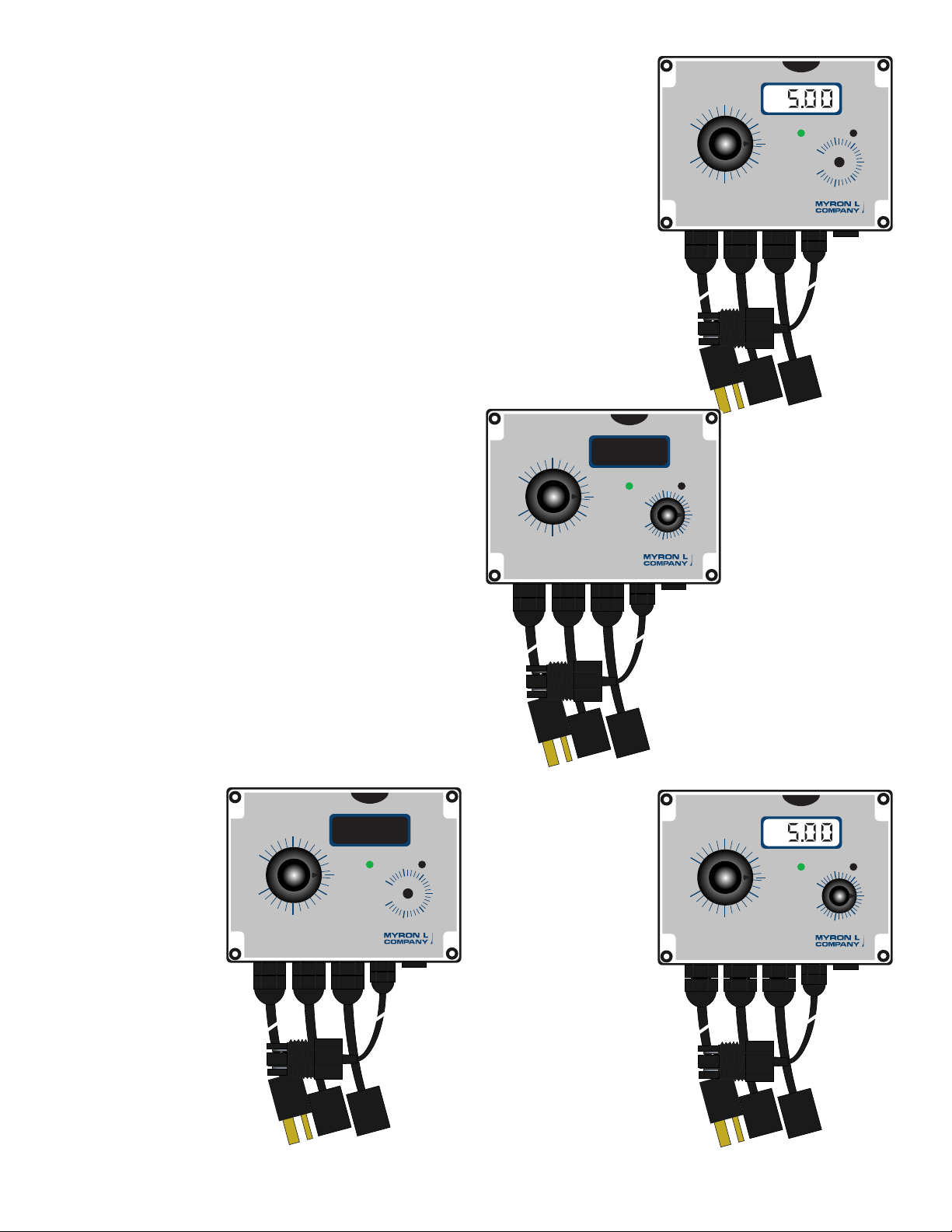
A. FRONT PANEL INDICATORS & CONTROLS
The front panel illustrations to the right and operational
descriptions have been provided to assist the user in identifying
and operating their CTCII controller.
Refer to Section IV.B for Setup procedures and Section IV.B.1 for
Check-Out procedures.
Controller with
LCD Display
CTCIID
1. GREEN LED INDICATOR
When the GREEN LED indicator light is ON the conductivity/TDS
reading is LOW or BELOW the set point. Controller relays are
OFF.
2. RED LED INDICATOR
When the RED LED indicator light is ON the conductivity/TDS
reading is HIGH or ABOVE the set point AND the controller relays
are ON.
3. SET POINT CONTROL
When the “SET POINT” control is rotated the LED indicator light
will change from GREEN to RED and back as the knob is rotated.
The relay will switch ON and OFF. See gures IV.A.1 thru 4.
4. DIGITAL DISPLAY MODELS
Digital display provide a continuous readout of the water being
controlled.
Models CTCIID & CTCIITD are equipped with a 3 1/2 digit, 1/2”
Liquid Crystal Digital Display, as shown in gures IV.A.2 & 4, with
a 4 1/2 digit backlit LCD as an option.
5. LIMIT TIMER MODELS
Models CTCIIT & CTCIITD incorporate a Limit Timer for the feed
pump. The time may be set up to 120 minutes after which the
pump will turn off even though the controller may still be bleeding.
While the feed pump Limit Timer is ON a YELLOW LED will turn
ON. When the Limit Timer times out the YELLOW LED will turn
OFF.
Figure IV.A.2
Controller
with Timer
CTCIIT
Figure IV.A.3
Basic
Controller
18
CTCII
Figure IV.A.1
Controller
with LCD
Display and
Timer
CTCIITD
Figure IV.A.4
Page 23

CAUTION - READ FOLLOWING CAREFULLY
!
B. SETUP PROCEDURES
These Setup procedures cover (1) checking out your new CTCII
Chemical Treatment Controller, (2) setting the control set point,
and (3) adjusting the hysteresis.
NOTE: A small screwdriver or tweaker will be required for some of
the following operations.
point at full scale as it leaves the factory. Under normal (most)
conditions it will not be necessary to adjust.
However, if you desire to make an adjustment please keep the
following in mind.
The adjustment is very simple and is based on set point location.
If the set point is in the upper 75-100% of the scale, the hysteresis
control pot should be turned fully to the right.
If the set point is in the lower portion of the scale, i.e. 5-25% of
scale, the control pot may be turned fully to the left.
If you are operating in the center, 25-75% of scale, the control pot
may be adjusted in the center.
Or the hysteresis or dead band may be adjusted to tighten the
control of a particular process.
1. CHECK-OUT PROCEDURES
The following check-out procedures are used to verify that the
CTCII Controller is operating properly. Refer to gure V.A.1. for
the locations of the components referred to in this section.
a. Assumed that the clear cover and the front panel are removed,
the power is ON.
b. Assumes above PLUS that the controller is connected to an
appropriate Sensor, and that the Sensor is immersed in water
within the range that the Controller will be required to operate.
c. Limit Timer check out procedure.
a. Sensor OUT of water.
1. While pressing the Electronic Calibration Switch (EC),
rotate the Set Point Control toward “EC” on the dial.
Listen for the control relays to click ‘ON and OFF’ as the
set point moves past the EC location. The indicator light
(LED) will change from RED to GREEN.
If equipped with a display, verify that the display
is indicating a reading of approx. 2.50. If not, see
Calibration, section V.B.
2. Adjust the Set Point Control to the desired set point
value.
3. Reassemble.
b. Sensor IN water.
1. Rotate the Set Point Control on the front panel.
The relays will click and the indicator light (LED) will
change from RED to GREEN and GREEN to RED as the
knob is rotated. As the relays click and the LED changes
from RED to GREEN this is the value of the water.
Make a note of the reading on the display if so equipped.
It will be very close to the value indicated by the set point
control knob.
2. Set the Set Point Control to the desired set point value.
3. Reassemble.
CAUTION: Adjusting the hysteresis too narrow may cause the
controller to uctuate (on-off) due to ow, chemical mixing or
bubbles causing the relay to chatter. This condition is to be
avoided, it could damage your valves, pumps, etc. and will
eventually damage the relay.
The following is assuming the front panel is already removed and
the set point has been set, if not see “Set Point Adjustment”.
1. Turn power ON.
2. Locate the Hysteresis Control (HYST) - it is a single turn
pot. See gure V.A.1.
3. Adjust as described in “Hysteresis (Dead Band)
Adjustment” or as desired.
4. Rotate set point control on the front panel to verify
Hysteresis is set as desired.
5. Turn power OFF.
4. “FEED PUMP” LIMIT TIMER
If installed, adjust timer control knob as desired, to limit the ON
time of the feed pump.
REASSEMBLY
1. Carefully reinstall the front panel.
2. Reinstall the clear cover.
3. Reinstall the four (4) screws and tighten.
4. To operate, turn power ON.
c. Limit Timer Check Out Procedure
If the Limit Timer is installed, a YELLOW LED located above the
timer knob will also be ON. To test:
1. Rotate the Limit Timer Control on the front panel from
its highest position to its lowest position. Only the FEED
PUMP relay will click OFF (the YELLOW indicator light
will turn OFF).
2. Adjust the Limit Timer to the desired time.
2. SET POINT ADJUSTMENT
The set point setting is based upon the user’s particular water
purity specications or requirements. Remove clear cover and
adjust control knob to desired set point value.
3. HYSTERESIS (DEAD BAND) ADJUSTMENT
The hysteresis or dead band is approximately ±6% of the set
19
Page 24
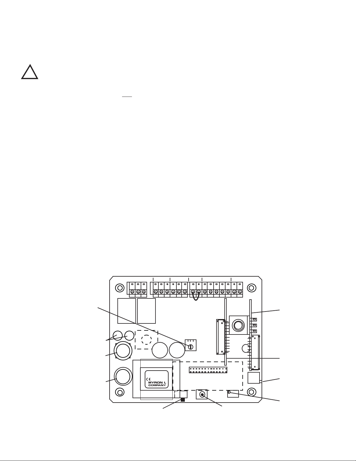
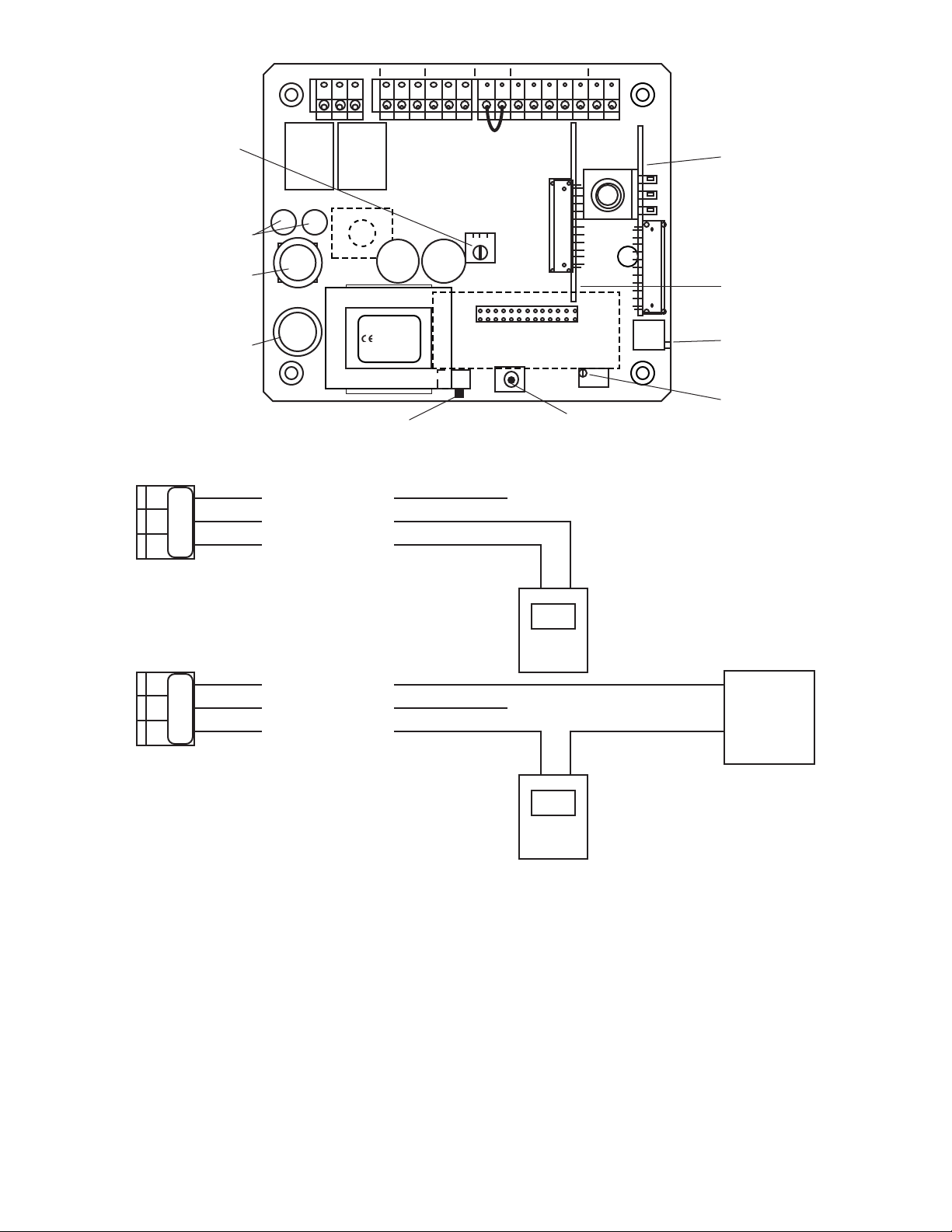
V. COMPONENT IDENTIFICATION,
CTCII MAIN CIRCUIT BOARD
Figure V.A.1
115/230 VAC
SELECT SWITCH
100mA Slow Blow
(T.10A)
115 & 230 VAC (V~)
SCALE SELECT
ELECTRONIC
CALIBRATION
MAIN
CALIBRATION
CONTROL
DISPLAY
CALIBRATION
CONTROL
(FACTORY SET)
OPTIONAL
LIMIT
TIMER
CONTROL
MODULE
OPTIONAL
4-20 mA
OUTPUT
MODULE
DIS
CAL
TDS COND
EC
CTCII
DISPLAY
TRANSFORMER
Yel
CAP CAP
C4AM
LTM
HYST
Flow Switch
Jumper Remove if
flow switch
installed.
SWITCH
FUSE
RELAY RELAY
BLEED FEED
FEED
PUMP
BLEED
VALVE
POWER
FLOW
SWITCH
SENSOR 0-10VDC
FS BK WTRD GN NU R- R+PWR C GDPWR C GDPWR C GD
SET POINT
HYSTERESIS
RIGHT INC
LEFT DEC
R/G
Wickman Fuse 5 Amp
(#3741500041 or equiv)
115 VAC(V~)
CALIBRATION AND PREVENTIVE CARE
A. PRIMARY COMPONENT IDENTIFICATION
As identied in Section III, the CTCII Chemical Treatment
Controllers main circuit board, controls and indicator lights are
mounted directly to the front panel.
Review gure V.A.1 below to familiarize yourself with the Main
circuit board assembly. The following diagram has the optional
Limit Timer Module and 4-20 mA Output Module installed.
20
Page 25

CAUTION - READ FOLLOWING CAREFULLY
!
B. CALIBRATION PROCEDURES
All Myron L CTCII Chemical Treatment Controllers are factory
calibrated prior to shipping and are ready to install without further
calibration. Calibration should be checked occasionally with
the internal Electronic Calibration Test switch (EC) to ensure
continued accuracy.
The following procedures are provided in the event that
recalibration becomes necessary. The only equipment required
are a tweaker or small screwdriver, and standard solution.
Refer to Figure V.A.1. to locate the components described in this
section.
WARNING: When performing calibration procedures, the
technician must take extreme care to avoid contacting the
circuitry other than the CALibration control. Failure to do so
could result in damage to the equipment, property and/or
personal injury.
1. ELECTRONIC CALIBRATION
(CIRCUIT ONLY)
This method is faster than the method using standard solution,
but it does not include the sensor. Therefore, it should be used
only in applications where the chance of sensor contamination or
damage are slight.
The Set Point control will be used to check the calibration.
NOTE: The DISplay calibration control (if display is installed)
has been set and sealed prior to leaving the factory, and under
normal conditions will not require readjustment. This allows the
user to observe the panel display (if installed) to visually set
the electronic value. If the DISplay calibration control has been
adjusted it will be necessary to, rst, verify or adjust the Set Point
Control Calibration as described in “Set Point Control Calibration”
below.
a. Set Point Control Calibration
1. Ensure power is OFF.
2. Using a Phillips Head screwdriver remove the four (4)
screws on the clear cover.
3. Remove clear cover.
4. The front panel is held in place with hook & loop strips
on each side. By carefully lifting at the slot on the top,
the front panel will pull toward you. Do not pull more than
about 8 inches/20CM.
DO NOT pull on control knob(s).
5. Rotate the front panel down so that the back side is
facing you. The Circuit Board is mounted to the back of
the front panel.
6. Turn power ON.
CAUTION: When handling Circuit Borad, DO NOT touch
component side. Electrical shock may occur.
7. Press and hold the Electronic Calibration switch (EC).
8. Rotate Set Point Control from “0” toward EC. At EC the
relay should click, and the LED should change from RED
to GREEN. If not, set Set Point control to EC and adjust
the CALibration control.
Models with 3 1/2 digit LCD.
The display should indicate 2.50.
If not, adjust the DISplay calibration control.
9. Turn power OFF.
10. Re-install front panel and cover as described in
“REASSEMBLY”.
11. To operate, turn power ON.
b. 0-10VDC Recorder Output Calibration
For output voltages other than 10VDC, substitute as required, i.e.
5.00VDC or 2.00VDC per Section II.F.2.
Requires a DVM set to DC Volts.
1. Ensure power is OFF.
2. Attach DVM to RECORDER output connection.
3. Turn power ON.
4. Press and hold the Electronic Calibration switch (EC).
5. The DVM should indicate 5.00VDC.
6. If not, adjust CALibration control until DVM indicates
5.00VDC.
7. Verify the set point control is set at EC point. If not,
loosen knob on shaft and reset to EC.
8. Verify the display (if installed) is indicating a reading
of 2.50. If not, adjust DISplay control until a full scale
reading is displayed.
9. Turn power OFF.
10. Re-install front panel and cover as described in
“REASSEMBLY” or continue.
11. To operate, turn power ON.
2. CALIBRATION USING
STANDARD SOLUTION
The best method of recalibrating your conductivity/TDS CTCII
Chemical Treatment Controller is with a NIST traceable Standard
Solution (available from the Myron L Company). Because it
includes the sensor, the entire system is recalibrated.
The following procedure describes the easiest method for
standard solution calibration of your Conductivity/TDS CTCII
Chemical Treatment Controller. We recommended using Myron L
442-3000 Standard Solution. This standard solution will calibrate
both Conductivity µS (at 3900 µS) and TDS ppm (at 3000 ppm)
modes.
1. Rinse thoroughly, and ll a clean glass beaker with the
standard solution.
2. Place sensor in the beaker of standard solution. The
level of standard solution must be high enough to cover
at least 1/2” above the electrodes.
3. Slowly shake the sensor to remove air bubbles from the
electrodes.
4. Allow 5-10 minutes for temperature to equilibrate. For
the quickest and the best results, both the sensor and
solution should be at the same temperature.
5. Turn power ON.
6. Rotated the Set Point control to 3900 for Conductivity
modes or 3000 for TDS modes. The relay should click
and the LED will change from RED to GREEN. Display
models (standard 3 1/2 digit).
The display should match the value of the standard
solution, 3900 µS (displayed as 3.90) or 3000 ppm
(displayed as 3.00).
If the reading is different, adjust CALibration control
on the main circuit board until the reading matches the
solution value.
7. After adjustment, turn power OFF.
8. Re-install front panel and cover as described in
“REASSEMBLY”.
9. To operate, turn power ON.
21
Page 26

3. TRANSFER STANDARD METHOD
For maximum accuracy of any Monitor/controller, the transfer
standard method should be utilized. Instead of removing the
entire Monitor/controller and sensor, and either returning it to
the manufacture or sending it to a third party laboratory for
recertication, the transfer standard allows quick recertication
and return to service — less down time. While being the most
accurate method it is also very easy to perform, and may be used
to calibrate ANY manufacture Monitor/controller — resistivity or
conductivity/TDS. This method still has the benet of third party
verication, if so desired.
1. A high quality hand-held instrument, one capable of
accurate conductivity/TDS readings such as the Myron L
Ultrameter™, is calibrated using a standard solution, or if
so desired, sent to a third party laboratory for calibration
& certication. Preferably the standard solution should
be as close as practicable to the area of the Monitor/
controller operation, i.e. for a conductivity Monitor/
controller that is operating between 1500 and 2000µS,
the recommended Myron L standard solution is KCl-
1800.
2. Once the Ultrameter is calibrated, the process water is
measured.
3. Finally, the Monitor/controller is calibrated/adjusted to
match the value measured by the Ultrameter by adjusting
the Main CALibration control shown in gure V.A.1.
4. Turn power OFF.
5. Re-install front panel as described below in
“REASSEMBLY”.
REASSEMBLY
1. Carefully reinstall the front panel.
2. Reinstall the clear cover.
3. Reinstall the four (4) screws and tighten.
4. If so desired, install corner covers.
5. To operate, turn power ON.
C. PREVENTIVE CARE
The Myron L Company recommends that the following Preventive
Care procedures be observed.
1. Try to prevent exposure to excessive heat and moisture.
2. The main AC power source should be protected against
excessive voltage “spikes.”
3. Take care not to damage the Monitor or sensor during
handling.
NOTE: Daily, weekly or monthly maintenance schedules are
based upon the frequency of use and the severity of the CTCII
Chemical Treatment Controllers environment and operating
conditions.
4. Repeat the Check-Out procedures to verify satisfactory
operation and/or isolate possible troubleshooting
symptoms.
5. Check all cable connections to ensure that they are free
of moisture and contamination.
6. Inspect and replace damaged component boards and
cable assemblies.
7. Periodically remove, clean and inspect the Sensor.
CLEANING - clean clear cover with soap and water, and soft nonabrasive cloth.
22
Page 27

VI. OPTIONS & ACCESSORIES
A. OPTIONS ORDERED WITH CTCII CONTROLLER
PART # DESCRIPTION
-C4A 4-20mA Self-Powered Isolated Output Module (Digital & OEM Only)
-45 4 1/2 Digit “Backlit” Liquid Crystal Display (LCD)
-35BL 3 1/2 Digit “Backlit” Liquid Crystal Display (LCD)
-51R CS51R, 316 SS conductivity sensor w/ 10 ft/3mtr cable (sensor upgrade)
SPECIAL ORDER OPTIONS
-24V 24 VAC Isolated Power
-24VD 24 VDC Isolated Power
-SQC Quik-connect, sensor cable M/F
* allow approximately three (3) weeks.
B. OPTIONS & ACCESSORIES ORDERED SEPARATELY
PART # DESCRIPTION
CLTMO Limit Timer Module w/ small knob (when ordered after initial purchase)
C4AO 4-20mA Self-Powered Isolated Output Module (Digital & OEM Only)
45O 4 1/2 Digit Backlit Liquid Crystal Display (LCD)
35BLO 3 1/2 Digit “Backlit” Liquid Crystal Display (LCD)
VR Powersupply, 24 VAC, 20VA. (115 VAC - Indoor use Only)
CC NIST Certicate without Sensor
CCS NIST Certicate with Sensor in Standard Solution
23
Page 28

C. STANDARD SOLUTIONS & BUFFERS
1. CONDUCTIVITY/TDS
STANDARD SOLUTIONS
Your CTCII Chemical Treatment Controller has been factory
certied to meet certain specications based on the appropriate
Myron L Company NIST traceable standard solution. This same
solution is available to you.
442-3000 3900 µS/µM Conductivity and 3000 ppm TDS
Other standard solutions are available to meet your needs or
requirements.
also mold inhibited and accurate to within ±0.01 pH units @ 25°C.
Order 4, 7 or 10 Buffer.
b. pH Sensor Storage Solution
Myron L Storage Solution prolongs the life of the pH sensor. It is
available in quarts and gallons. Order SSQ or SSG.
C.1.a. Potassium Chloride Standards
KCl-18
KCl-180
KCl-1800
KCl-18,000
DESCRIPTION
The Myron L Company manufactures three basic types of
conductivity/TDS standard solutions — KCl, NaCl and 442™. See
below.
Most Myron L standard solution bottles show three values
referenced at 25°C:
Conductivity in microsiemens/micromhos, while the ppm/TDS
equivalents are based on our 442 Natural Water™, and NaCl
standards. All standards are within ±1.0% of reference solutions.
These same buffers may be used for calibration and recertication
of your Myron L or other handheld instrument.
a. Potassium Chloride (KCl)
The concentrations of these reference solutions are calculated
from data in the International Critical Tables, Vol. 6.
b. 442 Natural Water™
442 Natural Water Standard Solutions are based on the following
salt proportions: 40% sodium sulfate, 40% sodium bicarbonate,
and 20% sodium chloride which represent the three predominant
components “anions” in freshwater. This salt ratio has conductivity
characteristics approximating fresh natural waters and was
developed by the Myron L Company over three decades ago. It is
used around the world for measuring both conductivity and TDS in
drinking water, ground water, lakes, streams, etc.
KCl-70
KCl-700
KCl-7000
KCl-70,000
C.1.b. 442 Natural Water Standards
442-15
442-150
442-1500
442-15,000
442-30
442-300
442-3000
442-30,000
442-500
442-1000
C.1.c. Sodium Chloride Standards
NaCl-12.5
NaCl-13.4
NaCl-14.0
c. Sodium Chloride (NaCl)
This is especially useful in sea water mix applications, as sodium
chloride is its major salt component. Most Myron L standard
solution labels show the ppm NaCl equivalent to the conductivity
and to ppm 442 values.
2. pH and ORP BUFFER SOLUTIONS
For your pH and/or ORP Monitor/controller. Your pH and ORP
Monitor/controller requires the same care and calibration as your
Conductivity/TDS Monitor/controller. With the following Myron L
Company NIST traceable buffer solutions it is possible for you to
maintain the accuracy required in your process.
NOTE: pH and/or ORP Monitor/controllers ORP ZERO is
calibrated using 7pH buffer. SPAN may be calibrated using any
high quality ORP mV solution.
These same buffers may be used for calibration and recertication
of your Myron L or other handheld instrument.
a. pH Buffer Solutions
pH buffers are available in pH values of 4, 7 and 10. Myron L
Company buffer solutions are traceable to NIST certied pH
references and are color-coded for instant identication. They are
24
C.2.a. pH Buffer Solutions
pH4.0
pH7.0
pH10.0
C.2.b. pH/ORP Storage Solution
SSQ - Quart/liter
SSG - Gallon
Customer Standard Solutions available by special order @
$90.00 per Gallon. Contact us with your request.
Order example:
KCl-7000GAL
442-3000QT
Page 29

VII. REPLACEMENT PARTS
Contact the Myron L Company for the latest prices.
PART # CONTROLLER MODEL For Timer Module see below
CTCIICB CTCII Circuit Board Digital controller only
CTCIIDCB CTCII Circuit Board Digital Monitor/controller
For Timer Module see below.
24V 24VAC Isolated Power, add to above prices
24VD 24VDC Isolated Power, add to above prices
If VOLTAGE is not specied, 115/230 VAC will be supplied.
TIMER MODULE
LTMO CTCII Timer Module
DIGITAL DISPLAYS
35O 3 1/2 Digit without Bezel
35BLO 3 1/2 Digit Backlit without Bezel
45O 4 1/2 Digit Backlit without Bezel
ENCLOSURE
CTCIIER CTC series II Rear Enclosure
CTCIIEL CTC series II Clear Lid w/ screws
CTCIIEC CTC series II Complete
FRONT PANEL with Label only
CTCIIFP Front Panel with LCD & Timer Label
OPTIONS & ACCESSORIES
F100 Fuse; 115/230 VAC Control Board, 100mA (T.10A) 5 X 20 Slow Blow/Time Delay
F250 Fuse; 24 VAC Control Board, 250mA (T.25A) 5 X 20 Slow Blow/Time Delay
FUSE5A Fuse; 115/230 (CTCII Relays, 5 amp (Wickman subminature Fuse P/N 3741500041)
25
Page 30

VIII. WARRANTY
Your Myron L Company CTCII Chemical Treatment Controller and sensor have a TWO-year limited warranty. If any controller or sensor
fails to function normally, return the faulty unit to the factory prepaid. If, in the opinion of the factory, failure was due to materials or
workmanship, repair or replacement will be made without charge.
A reasonable service charge will be made for diagnosis or repairs due to normal wear, abuse or tampering. Warranty is limited to the
repair or replacement of Monitor/controller or sensor only. The Myron L Company assumes no other responsibility or liability.
MYRON L COMPANY
2450 Impala Drive
Carlsbad, CA 92008-7226 USA
Tel: 760-438-2021
Fax: 760-931-9189
www.myronl.com
ADDITIONAL INFORMATION
Custom Monitors/controllers available, contact us with your special needs. Price and delivery upon request.
ALL SPECIAL ORDER ITEMS ARE NON-RETURNABLE AND NON-REFUNDABLE.
Because of our policy of continuous product improvement, the Myron L Company reserves the right to make changes in design,
specications, and prices without notice.
Minimum order $25.00. All prices are US dollars and are F.O.B Carlsbad, CA. USA.
Terms: 1% 10 days, net 30 days upon receipt of sufcient credit information.
Export orders: payment in advance, sight draft collection, or credit card.
26
Page 31

IX. GLOSSARY
442™ An Internationally recognized “natural water”
standard developed by the Myron L Company in
1964.
Algorithm A procedure for solving a mathematical
problem. See Addendum, Temperature
Compensation and TDS Derivation.
Anions Negatively charged ions
DVM Digital Volt Meter
Hysteresis Dead Band — related to alarm set point. The
amount of delay or overlap between change
from high to low or low to high.
LCD Liquid Crystal Display
KCl Potassium Chloride — used as a standard for
many applications.
Normally, micromhos or microsiemens are the
units of measure.
NaCl Sodium Chloride — used as a standard for sea
water and other applications.
of Cond/TDS, Resistivity or pH device but
must not actual correct measurements for
temperature errors).
NIST National Institute Standards & Testing
PLC Programmable Logic Controller
PPM Parts Per Million — common units of measure
for TDS.
PPT Parts Per Thousand — common units of
measure for TDS.
SCADA Supervisory Control And Data Acquisition
Tempco (TC) Temperature Compensation — See Addendum,
Temperature Compensation.
TDS Total Dissolved Solids, the Total Conductive
Ions in a solution — normally displayed as ppm
or ppt. See Addendum, Conductivity Conversion
to TDS.
Tweaker A screwdriver specially designed for adjusting
electrical calibration controls.
µM or µS Micromho or microsiemen — common unit of
measure for conductivity.
Meg or MΩ Megohm — common unit of measurement for
resistivity.
USP25 United States Pharmaceutical regulation,
revision number 25. In part, requires
Conductivity/TDS, resistivity or pH
measurements be taken, recorded and/or
systems controlled using equipment without
temperature compensation. Requires a
separate temperature measuring device
(temperature measurements may be part
27
Page 32

X. NOTES
28
Page 33

XI. ADDENDUM
29
Page 34

XI. ADDENDUM Continued
30
Page 35

Page 36

MYRON L COMPANY
Water Quality Instrumentation
Accuracy • Reliability • Simplicity
2450 Impala Drive
Carlsbad, CA 92008-7226 USA
Tel: 760-438-2021
Fax: 760-931-9189
Made In USA
www.myronl.com
ACCURACY • RELIABILITY • SIMPLICITY
 Loading...