

Myron L bluDock Ultrameter III, bluDock PoolPro, bluDock Digital Dialysate Meter, bluDock Ultrameter II Installation Instructions Manual
Page 1
bluDock™ INSTALLATION INSTRUCTIONS
Ultrameter II™, Ultrameter III™, PoolPro™ and Digital Dialysate Meter™
NOTE: Please read these instructions thoroughly and carefully — Damage caused by improper installation or
mishandling will void the warranties of the instrument and the new bluDock module.
CAUTION: Moisture trapped in the instrument will cause damage. Careful adherence to the following procedure will
signicantly reduce the potential for failure due to moisture contamination.
While the instrument is open, we recommend you replace the battery with a new 9V alkaline battery. For clarity, this
procedure is broken down into four sections. Follow each section carefully to avoid damage. Refer to the drawings on
the back of this document as necessary.
I. Preparing and Opening the Instrument Case
1. Remove the pH/ORP protective cap from the sensor well, shake out the sensor storage solution, rinse
with clean water, and thoroughly dry the sensor well and reinstall the protective cap.
2. If the instrument is wet, dry it thoroughly before proceeding, paying particular attention to the bottom
screw holes. Ensure your hands are clean and dry. Moisture will damage the electronics.
3. Turn the instrument over and set it on a clean, dry surface.
4. Using a Phillips screwdriver, remove the 4 bottom screws.
5. Open the instrument carefully. While removing bottom case, ensure the sealing gasket does not stick
to the bottom case, and stays in the top case groove. If the gasket comes out, handle it carefully and
reinstall it in the top case groove. Exercise extreme care not to allow any water to enter the open case.
II. Installing the bluDock Module
1. For the Ultrameter II Model 4P and the Digital Dialysate Meter Model D-4, skip to step 2.
For all other models: Locate the pH and ORP cables and (without disconnecting them) lift them up off
the circuit board enough to allow clearance for installing the bluDock module underneath them.
2. Remove the bluDock module from its packaging.
3. Hold the instrument in your left hand and the bluDock module with the Myron L® label facing up in your
right hand.
4. Plug the bluDock module into the bluDock connector. See Figure 2 on the back of this document.
Ensure the module is inserted securely into the connector.
5. For the Ultrameter II Model 4P and the Digital Dialysate Meter Model D-4, skip to step 6.
For all other models: Lay the pH and ORP cables back down against the circuit board, the Red cable
along the left side, and the Black cable along the right side. Align the cables so that they will NOT
obstruct or become pinched by the bottom case or standoff while reinstalling the bottom case. See
Figure 3 on the back of this document.
6. Thoroughly inspect and clean both top and bottom case (paying special attention to the case seal),
screw wells and screws.
III. Closing the Instrument Case
1. Ensure the sealing gasket is installed in the groove of the top case.
2. Replace the bottom case, aligning it with the groove.
3. Install and start the 4 bottom screws.
4. Tighten the screws evenly and securely in a crisscross pattern. See Figure 4 on the back of this
document. A waterproof seal cannot be ensured unless the screws are secure. Uneven tightening will
cause the instrument to rock.
5. For the Ultrameter II Model 4P and the Digital Dialysate Meter Model D-4, installation is complete.
For all other models: Turn instrument over and ll the pH/ORP sensor well with Myron L® pH/ORP
Sensor Storage Solution and reinstall the protective cap.
IV. Installing the Bluetooth Enabled “bD” Label on the Keypad
1. Clean the keypad so that it is free of any oil or soap and dry
thoroughly.
2. Apply the label underneath the model number on the
keypad and hold it rmly in place for at least 30 seconds.
Your instrument is now ready for wireless data transfer. See the
instrument and/or Guardian2 Operation
TM
Manual for further instructions.
2450 Impala Drive
Carlsbad, CA 92010-7226 USA
Tel: +1-760-438-2021
Fax: +1-800-869-7668 / +1-760-931-9189
www.myronl.com
®
BDII 07-19
Page 2
W
n
Acc uracy • Re liabi lit y • S impli city
www.myronl.com
6PFC Ultrameter ll Shown
E
2450 Impala Drive
Carlsbad, CA 92010-7226 USA
Tel: +1-760-438-2021
Fax: +1-800-869-7668 / +1-760-931-9189
Figure 1
6PFC Ultrameter ll Shown
E
9 Volt
Alkaline
Battery
installing the
bluDock module
underneath
them.
ORP
cables up off
the circuit board
enough to allow
clearance for
pH
Lift the pH and
ORP sensor
bluDock
connector
bluDock
Connector
bluDock
SFP-MSA
connector
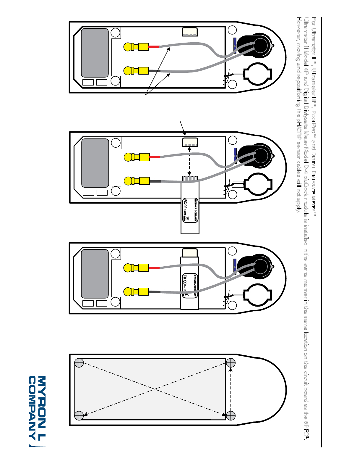
For Ultrameter II™, Ultrameter III™, PoolPro™ and Digital Dialysate Meter™
Ultrameter II Model 4P and Digital Dialysate Meter Model D-4 bluDock module is installed in the same manner in the same location on the circuit board as the 6PFC
However, moving and repositioning the pH/ORP sensor cables will not apply.
bluDock
TM
Installation Illustrations
Figure 2
6PFC Ultrameter ll Shown
E
Figure 3
9 Volt
Alkaline
Battery
9 Volt
Alkaline
Battery
module and
position as
shown.
under the pH
and ORP sensors
cables and plug
it into the bluDock
connector.
cables back
down over the
installed
bluDock
circuit board
pH
ORP
Slide the bluDock
circuit board
pH
ORP
Lay the pH
and ORP
PN: BLUDOCK
bluDock
module
bluDock
SFP-MSA
connector
PN: BLUDOCK
bluDock
module
MYRON L COMPANY
bluDock
TM
MYRON L COMPANY
bluDock
TM
BDII 07-19
6PFC Ultrameter ll Shown
E
ater Qu al ity Instrum en tatio
Figure 4
®
1
4
Tighten
screws
in a
crisscross
pattern.
23
E
.
 Loading...