

Page 1

Water Quality Instrumentation
Accuracy • Reliability • Simplicity
750 Series
CONDUCTIVITY/TDS
&
RESISTIVITY
MONITOR/CONTROLLER
Operation
Manual
25 January 06
INSTALLATION • OPERATION • MAINTENANCE
ACCURACY • RELIABILITY• SIMPLICITY
Page 2

750 Series II MONITOR/CONTROLLER
QUICK REFERENCE GUIDE!
If you read nothing else in this
manual please read this
Quick Reference Guide.
PLEASE READ and COMPREHEND ALL
WARNINGS, CAUTIONS and ADVISEMENTS
CONTAINED WITHIN THIS MANUAL.
Failure to comply is beyond the responsibility of
the Myron L Company.
WARNING: ALL MONITOR/CONTROLLERS ARE
FACTORY SET TO OPERATE ON 115 VAC. BEFORE
APPLYING POWER ENSURE THE INPUT POWER
“115/230 VAC” SELECTION IS CORRECT FOR YOUR
REQUIREMENTS. FAILURE TO DO SO IS BEYOND
THE RESPONSIBILITY OF THE MYRON L COMPANY.
See section II.E.2. and figure II.E.1.
NOTE: SOME MODELS MAY HAVE EITHER A 24 VAC
OR A 24 VDC INPUT POWER REQUIREMENT - CHECK
LABELS CAREFULLY.
WARNING: ENSURE POWER IS OFF WHILE
INSTALLING ELECTRICAL EQUIPMENT. IF
MONITOR/ CONTROLLER IS INSTALLED, ENSURE
THE POWER IS OFF BEFORE SERVICING. FAILURE
TO DO SO COULD CAUSE DAMAGE TO THE
INSTRUMENT, AND COULD BE HARMFUL OR FATAL
TO PERSONNEL. ONLY QUALIFIED PERSONNEL
SHOULD INSTALL OR SERVICE ELECTRICAL
EQUIPMENT.
WARNING: THE DISPLAY WILL BE IRREPARABLY
DAMAGED IF THE DISPLAY HARNESS IS INSTALLED
UPSIDE-DOWN OR MISALIGNED. THE HARNESS
MUST BE INSTALLED AS SHOWN IN FIGURE II.E.8.
CAUTIONS:
Before installation, ensure you have the correct
model (with options), AND it is ranged for your
application. See sections I.A., I.B. & I.G.
Do you have the correct sensor? See section I.E.
Mounting requirements. What is needed? See
section II.B.
The following will give the installer and user a quick
overview. See the sections listed for details.
REMOVING FRONT PANEL
NOTE: When opening instrument, remove front cover with care;
a ribbon cable connects the front panel and main board.
1. Ensure power is OFF.
2. Remove the two (2) screws on the front panel.
3. Carefully wiggle the front panel to loosen the gasket and
pull gently toward you. Do not pull more than about 8
inches/20CM or you could damage the wiring harness.
REASSEMBLY
1. Carefully reinstall the front panel, bottom first.
Ensure no wires have been pinched between enclosure
and front panel.
2. Reinstall the two (2) screws and tighten.
3. To operate, turn power ON.
INTRODUCTION - Section I.
This section covers the specifications of your new
Monitor/controller including sensor information.
INSTALLATION - Section II.
This section covers how to install your new Monitor/controller;
mechanically and electrically.
OPTIONS & ACCESSORIES - Section III.
This section covers the specifications, installation, set up, and
operation of each option.
QUICK LOCATOR
SC/SCO MODULE, (Second Relay), see section III.A.
4A/4AO MODULE (4-20mA), see section III.B.
TP/TPO MODULE (Temperature), see section III.C.
TH/THO MODULE (Alarm /control Harness), see section III.D.
DUAL (stacking) Temperature (TPO) & 4-20mA (4A/4AO), see
section III.E.
3SO/3SE MODULE (3 Sensor option) , see section III.F.
3RO/3RE MODULE (3 Range option), see section III.G.
3SRO/3SRE MODULE (Combined 3 Sensor & 3 Range option),
see section III.H.
PA/PAO (Piezo Alarm), see section III.I.
RA (Remote Alarm), see section III.J.
OPERATING PROCEDURES - Section IV.
This section covers a brief description of different models and
their features; how they work, and how to set them up for your
particular use.
QUICK SET POINT CONVERSION (SPC) /
REVERSING SET POINT - See Section IV.C.1.
Conductivity/TDS Monitor/controllers are configured to trigger the
alarm relay as the conductivity/TDS reading increases.
Resistivity Monitor/controllers are configured to trigger the alarm
relay as the resistivity reading decreases.
To reverse:
1. Locate the jumper block for the alarm to be configured.
See figure V.A.1.
2. Remove and rotate the jumpers 1/4 turn and reinstall
them on their posts.
QUICK CHECK-OUT PROCEDURE -
See Section IV.C.2.
It is assumed that the Monitor/controller power is ON, that it is
Continued
Page 3
connected to an appropriate Sensor, and that the Sensor is
immersed in water within the range that the Monitor/controller will
be required to read; and the front panel is removed.
1. Make a note of the reading on the display.
2. While pressing the Calibration/Full Scale Test Switch (FS
SW), verify that the front panel display is indicating a full
scale reading. If not, see Calibration, section V.C.
3. Press and hold the "SET POINT" switch on the front
panel. Using a tweaker or a small screwdriver, adjust the
Set Point trimmer adjustment screw on the circuit board
to sweep the display from zero to full scale. (A digital
display may be blank at the full scale end. This is
normal.) Listen for the alarm relay to click on and off as
the alarm set point moves past the water reading.
4. Adjust the alarm to the desired set point value. Release
the "SET POINT" switch.
NOTE: For Models with SC/SCO module, repeat STEPS 3 & 4 to
check out Set Point #2.
QUICK SET POINT ADJUSTMENT -
See Section IV.C.3.
The set point setting is based upon the user's particular water
purity specifications or requirements. NOTE: The optional
second relay/alarm is “stacked” on the first relay/alarm,
therefore, when setting the optional second relay/alarm Set
Point, the #1 Set Point must be ‘set’ first.
1. While pressing the "SET POINT" switch, turn the Set
Point #1 adjustment screw (see figure V.A.1) until the
desired set point value is indicated on the display.
HYSTERESIS (DEAD BAND) ADJUSTMENT -
See Section IV.C.4.
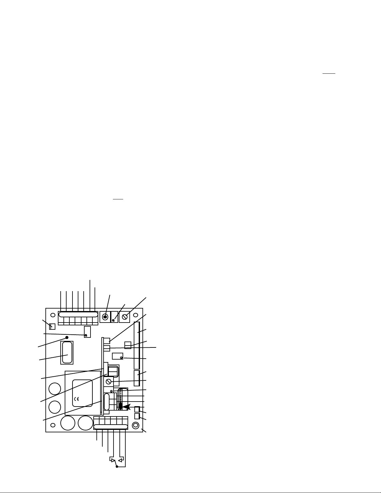
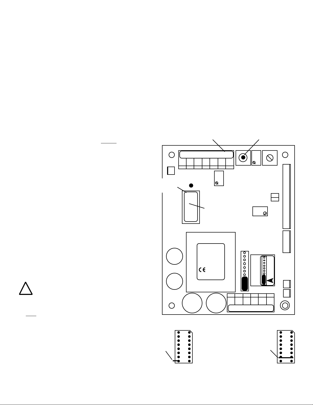
PRIMARY COMPONENT IDENTIFICATION -
Section V.A.
Review the figure below to familiarize yourself with the Main circuit
(-)
0-10VDC OUTPUT
3SO/3SE &/OR
3RO/3RE
SWITCH
CONNECTION
MAIN
CALIBRATION
CONTROL
RANGE
MODULE
ALIGNMENT
RANGE
MODULE
SC/SCO
OPTIONAL
SECOND
ALARM/
CONTROL
MODULE
#2 RELAY
LIGHTS &
SWITCH
CONNECTOR
RUBBER TAPE
(DO NOT
REMOVE)
Figure V.A.1
SENSOR
B
W
R
L
H
E
K
T
D
BK WT RD GN NU R- R+
3S
}
UP
-121
2000µS
TRANSFORMER
115/
230
POWER
{
G
N
R
E
N
U
CAL
INC
751 756
752 757
753 758
754 759
MYRON L
COMPANY
FUSE*
AC AC GD NC NO CM
AC HOT/ +DC
AC NEUTRAL/ -DC
GROUND
(+)
FULL SCALE
PUSH TO TEST
SET POINT
#1 CONTROL
PA
INC
DIS
SPC
INC
CM NO NC
NC NO
HYS1SP1FS SW
SPC
SECOND RELAY
REMOVE TO INSTALL
COM
DEC
SET POINT #1
HYSTERESIS
RIGHT INC
LEFT DEC
SOLID STATE (24VDC 30mW)
OUTPUT
PA™ PIEZO ELECTRIC ALARM
OR
RA™ REMOTE ALARM OR
CUSTOMER CONNECTION
DISPLAY/METER
CONNECTOR
SET POINT #1
CONVERSION
DISPLAY CALIBRATION
CONTROL (FACTORY SET)
4-20 CONNECTOR
SET POINT #2 HYSTERESIS
RIGHT INC / LEFT DEC
SET POINT #2 CONTROL
NC
NO
COM
+
SOLID STATE (24VDC 30mW)
+
OUTPUT
PA RA
RA™ REMOTE ALARM AND
PA™ PIEZO ELECTRIC ALARM
OR
CHS
GND
CUSTOMER CONNECTION
CHASSIS GROUND - OEM
RELAY #1
}
SET POINT #2
CONVERSION
RELAY #2
}
board assembly. The diagram has the second alarm/control
module option installed.
QUICK CALIBRATION - Section V.C.
WARNING: When performing calibration procedures,
the technician must take extreme care to avoid
contacting the circuitry other than the CALibration
control. Failure to do so could result in damage to
the equipment, property and/or personal injury.
The following assumes the front panel has been
removed and the power is ON.
ELECTRONIC CALIBRATION (CIRCUIT ONLY) -
See Section V.C.1.
Full Scale Adjustment
1. Press and hold the Full Scale Test switch. The display
should indicate Full Scale for the particular range
selected, i.e. 0-500 ppm should indicate 500. If not, set
to Full Scale with the CALibration control.
2. Turn power OFF.
3. Re-install front panel as described in “REASSEMBLY”.
4. To operate, turn power ON.
10VDC Calibration - See Section V.C.1.b.
Using Standard Solutions - Section V.C.2.
The BEST method of verifying and recalibrating your
conductivity/TDS Monitor/controller is with NIST traceable
Standard Solution (available from the Myron L Company).
Because it includes the sensor, the entire system is recalibrated.
NOTE: Since standard solution calibrations are NOT practicable
with resistivity models, another means of verification or
calibration of resistivity models is to use the transfer standard
method, using a hand-held or portable instrument capable of
resistivity measurements, i.e. the Myron L Ultrameter™. See
section V.C.4 for description.
The following procedure describes the easiest method for
standard solution calibration of your Conductivity/TDS
Monitor/controller.
1. Using a standard solution which is 60-90% of full scale
of the instrument, rinse thoroughly and fill a clean glass
beaker with the standard solution.
2. Place sensor in the beaker of standard solution. The
level of standard solution must be high enough to cover
at least 1/2" above cross hole.
3. Slowly shake the sensor to remove air bubbles from
inside the sensor bore hole.
4. Allow 5-10 minutes for temperature to equilibrate. For the
quickest and the best results, both the sensor and
solution should be at the same temperature.
5. Turn power ON.
6. If the reading is different from the standard solution,
adjust CALibration control on the main circuit board until
the reading matches the solution value.
7. After adjustment, turn power OFF.
8. Re-install front panel as described in “REASSEMBLY”.
9. To operate, turn power ON.
SENSOR SUBSTITUTE CALIBRATION -
See Section V.C.3.
TRANSFER STANDARD METHOD - See Section V.C.4.
14 Jan 03
Page 4
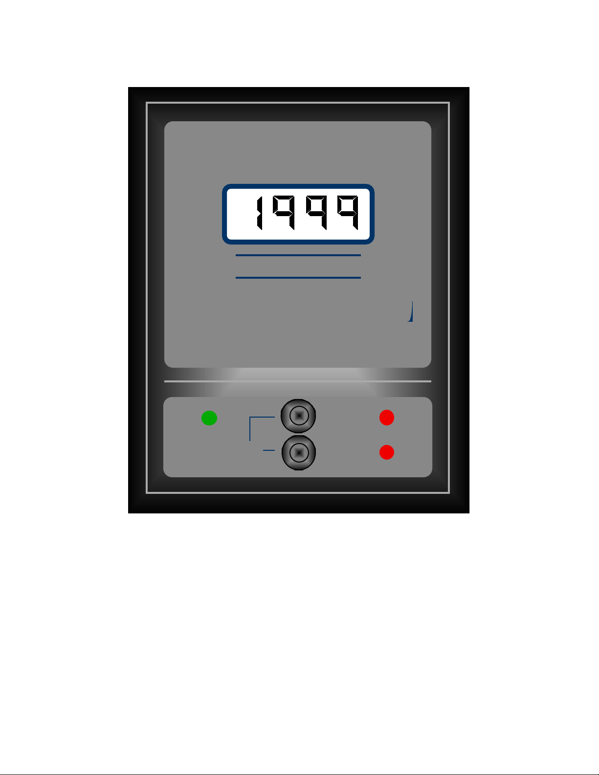
MICROSIEMENS / CM
750II
MYRON L
COMPANY
HIGH
LOWSET POINT
750 Series II
Model 758II-121-SC
(A Digital Conductivity
Monitor/controller,
with a Range of 0-2000 µS,
and a Second Alarm/Control)
1
Page 5

TABLE OF CONTENTS
SECTION PAGE
750 Series II ILLUSTRATION (758II-121-SC) . . . . . . . . . . . . . . . . . . . . . . . . . . . . . . . . . . . . . . . . . . . . . . 1
I. INTRODUCTION . . . . . . . . . . . . . . . . . . . . . . . . . . . . . . . . . . . . . . . . . . . . . . . . . . . . . . . . . . . . . . . . . . . . . . . . . . 5
A. SCOPE . . . . . . . . . . . . . . . . . . . . . . . . . . . . . . . . . . . . . . . . . . . . . . . . . . . . . . . . . . . . . . . . . . . . . . . . . . . . . 5
1. Functional Descriptions . . . . . . . . . . . . . . . . . . . . . . . . . . . . . . . . . . . . . . . . . . . . . . . . . . . . . . . . . 5
2. Applications . . . . . . . . . . . . . . . . . . . . . . . . . . . . . . . . . . . . . . . . . . . . . . . . . . . . . . . . . . . . . . . . . . 5
B. SPECIFICATIONS . . . . . . . . . . . . . . . . . . . . . . . . . . . . . . . . . . . . . . . . . . . . . . . . . . . . . . . . . . . . . . . . . . . . 5
C. OPTIONAL FEATURES . . . . . . . . . . . . . . . . . . . . . . . . . . . . . . . . . . . . . . . . . . . . . . . . . . . . . . . . . . . . . . . . 6
D. ACCESSORIES . . . . . . . . . . . . . . . . . . . . . . . . . . . . . . . . . . . . . . . . . . . . . . . . . . . . . . . . . . . . . . . . . . . . . . 6
E. SENSORS . . . . . . . . . . . . . . . . . . . . . . . . . . . . . . . . . . . . . . . . . . . . . . . . . . . . . . . . . . . . . . . . . . . . . . . . . . 7
1. Conductivity/TDS . . . . . . . . . . . . . . . . . . . . . . . . . . . . . . . . . . . . . . . . . . . . . . . . . . . . . . . . . . . . . 7
2. Resistivity . . . . . . . . . . . . . . . . . . . . . . . . . . . . . . . . . . . . . . . . . . . . . . . . . . . . . . . . . . . . . . . . . . . 7
3. Sensor Specifications . . . . . . . . . . . . . . . . . . . . . . . . . . . . . . . . . . . . . . . . . . . . . . . . . . . . . . . . . .7
F. ORDER INFORMATION . . . . . . . . . . . . . . . . . . . . . . . . . . . . . . . . . . . . . . . . . . . . . . . . . . . . . . . . . . . . . . . . 7
1. How to order Monitor/controller . . . . . . . . . . . . . . . . . . . . . . . . . . . . . . . . . . . . . . . . . . . . . . . . . . . 7
2. How to order Sensors . . . . . . . . . . . . . . . . . . . . . . . . . . . . . . . . . . . . . . . . . . . . . . . . . . . . . . . . . . 7
G. RANGE SELECTION GUIDE . . . . . . . . . . . . . . . . . . . . . . . . . . . . . . . . . . . . . . . . . . . . . . . . . . . . . . . . . . . . 8
II. INSTALLATION . . . . . . . . . . . . . . . . . . . . . . . . . . . . . . . . . . . . . . . . . . . . . . . . . . . . . . . . . . . . . . . . . . . . . . . . . . . 9
A. GENERAL . . . . . . . . . . . . . . . . . . . . . . . . . . . . . . . . . . . . . . . . . . . . . . . . . . . . . . . . . . . . . . . . . . . . . . . . . . 9
B. MECHANICAL INSTALLATION . . . . . . . . . . . . . . . . . . . . . . . . . . . . . . . . . . . . . . . . . . . . . . . . . . . . . . . . . . 9
1. Surface Mounting with SMP (surface mounting plate) Assembly . . . . . . . . . . . . . . . . . . . . . . . . . 9
2. Surface Mounting without SMP Assembly . . . . . . . . . . . . . . . . . . . . . . . . . . . . . . . . . . . . . . . . . . 9
3. Panel Mounting . . . . . . . . . . . . . . . . . . . . . . . . . . . . . . . . . . . . . . . . . . . . . . . . . . . . . . . . . . . . . . . 9
C. OEM MECHANICAL INSTALLATION . . . . . . . . . . . . . . . . . . . . . . . . . . . . . . . . . . . . . . . . . . . . . . . . . . . . . 10
1. Circuit Board . . . . . . . . . . . . . . . . . . . . . . . . . . . . . . . . . . . . . . . . . . . . . . . . . . . . . . . . . . . . . . . . 10
2. Analog Meter . . . . . . . . . . . . . . . . . . . . . . . . . . . . . . . . . . . . . . . . . . . . . . . . . . . . . . . . . . . . . . . . 10
3. Digital Display . . . . . . . . . . . . . . . . . . . . . . . . . . . . . . . . . . . . . . . . . . . . . . . . . . . . . . . . . . . . . . . 10
D. SENSOR INSERTION / DIP MOUNT ASSEMBLIES . . . . . . . . . . . . . . . . . . . . . . . . . . . . . . . . . . . . . . . . . .11
1. Insertion Mode Assembly . . . . . . . . . . . . . . . . . . . . . . . . . . . . . . . . . . . . . . . . . . . . . . . . . . . . . . 11
2. Alternate Dip Sensor Assembly . . . . . . . . . . . . . . . . . . . . . . . . . . . . . . . . . . . . . . . . . . . . . . . . . . 11
E. ELECTRICAL INSTALLATION . . . . . . . . . . . . . . . . . . . . . . . . . . . . . . . . . . . . . . . . . . . . . . . . . . . . . . . . . . 11
1. Main AC Power Installation . . . . . . . . . . . . . . . . . . . . . . . . . . . . . . . . . . . . . . . . . . . . . . . . . . . . . 11
2. 115/230 VAC Conversion . . . . . . . . . . . . . . . . . . . . . . . . . . . . . . . . . . . . . . . . . . . . . . . . . . . . . . .12
3. Connecting the Sensor Cable . . . . . . . . . . . . . . . . . . . . . . . . . . . . . . . . . . . . . . . . . . . . . . . . . . . 12
a. Modification for US Pharmaceutical 25 (No Temperature Compensation) . . . . . . . . . . . . . . 12
4. Solid State Output Connection . . . . . . . . . . . . . . . . . . . . . . . . . . . . . . . . . . . . . . . . . . . . . . . . . . 13
a. Piezo Electric Alarm Installation (option) . . . . . . . . . . . . . . . . . . . . . . . . . . . . . . . . . . . . . . .13
b. Remote Alarm Connection (RA option) . . . . . . . . . . . . . . . . . . . . . . . . . . . . . . . . . . . . . . . . .13
c. Connect to your own alarm or ? . . . . . . . . . . . . . . . . . . . . . . . . . . . . . . . . . . . . . . . . . . . . . . . 14
5. Alarm/Control Relay Connection . . . . . . . . . . . . . . . . . . . . . . . . . . . . . . . . . . . . . . . . . . . . . . . . . 14
6. Connecting Display Harness to Display . . . . . . . . . . . . . . . . . . . . . . . . . . . . . . . . . . . . . . . . . . . .14
F. 0-10 VDC OUTPUT . . . . . . . . . . . . . . . . . . . . . . . . . . . . . . . . . . . . . . . . . . . . . . . . . . . . . . . . . . . . . . . . . . . 15
1. Connection . . . . . . . . . . . . . . . . . . . . . . . . . . . . . . . . . . . . . . . . . . . . . . . . . . . . . . . . . . . . . . . . . .15
2. Voltage Divider . . . . . . . . . . . . . . . . . . . . . . . . . . . . . . . . . . . . . . . . . . . . . . . . . . . . . . . . . . . . . . .15
G. RE-RANGE YOUR MONITOR/CONTROLLER (Range Module Installation) . . . . . . . . . . . . . . . . . . . . . . . . 16
1. Description . . . . . . . . . . . . . . . . . . . . . . . . . . . . . . . . . . . . . . . . . . . . . . . . . . . . . . . . . . . . . . . . . .16
2. Installation . . . . . . . . . . . . . . . . . . . . . . . . . . . . . . . . . . . . . . . . . . . . . . . . . . . . . . . . . . . . . . . . . .16
3. Changing Analog Meter Scale (dial) . . . . . . . . . . . . . . . . . . . . . . . . . . . . . . . . . . . . . . . . . . . . . . . 17
4. Label Change . . . . . . . . . . . . . . . . . . . . . . . . . . . . . . . . . . . . . . . . . . . . . . . . . . . . . . . . . . . . . . . . 18
III. OPTIONS & ACCESSORIES INSTALLATION . . . . . . . . . . . . . . . . . . . . . . . . . . . . . . . . . . . . . . . . . . . . . . 19
A. SC/SCO MODULE (SECOND ALARM/CONTROL OPTION) . . . . . . . . . . . . . . . . . . . . . . . . . . . . . . . . . . . . 19
1. Description . . . . . . . . . . . . . . . . . . . . . . . . . . . . . . . . . . . . . . . . . . . . . . . . . . . . . . . . . . . . . . . . . .19
2. Installation . . . . . . . . . . . . . . . . . . . . . . . . . . . . . . . . . . . . . . . . . . . . . . . . . . . . . . . . . . . . . . . . . . 19
a. Set Point Conversion (SPC) / Reversing Set Point . . . . . . . . . . . . . . . . . . . . . . . . . . . . . . . 20
b. Set Point Adjustment . . . . . . . . . . . . . . . . . . . . . . . . . . . . . . . . . . . . . . . . . . . . . . . . . . . . . . 21
c. Hysteresis . . . . . . . . . . . . . . . . . . . . . . . . . . . . . . . . . . . . . . . . . . . . . . . . . . . . . . . . . . . . . . 22
d. Second Relay Connection . . . . . . . . . . . . . . . . . . . . . . . . . . . . . . . . . . . . . . . . . . . . . . . . . . 22
e. Solid State Options . . . . . . . . . . . . . . . . . . . . . . . . . . . . . . . . . . . . . . . . . . . . . . . . . . . . . . . 22
2
Page 6

TABLE OF CONTENTS Continued
SECTION PAGE
B. 4A/4AO MODULE (4-20mA OPTION) . . . . . . . . . . . . . . . . . . . . . . . . . . . . . . . . . . . . . . . . . . . . . . . . . . . . .23
1. Description . . . . . . . . . . . . . . . . . . . . . . . . . . . . . . . . . . . . . . . . . . . . . . . . . . . . . . . . . . . . . . . . . . 23
2. Installation . . . . . . . .. . . . . . . . . . . . . . . . . . . . . . . . . . . . . . . . . . . . . . . . . . . . . . . . . . . . . . . . . . 23
3. Recalibration . . . . . . . . . . . . . . . . . . . . . . . . . . . . . . . . . . . . . . . . . . . . . . . . . . . . . . . . . . . . . . . . 24
4. Converting a Current to a Voltage . . . . . . . . . . . . . . . . . . . . . . . . . . . . . . . . . . . . . . . . . . . . . . . . 26
C. TP/TPO MODULE (TEMPERATURE OPTION) . . . . . . . . . . . . . . . . . . . . . . . . . . . . . . . . . . . . . . . . . . . . . . 27
1. Description . . . . . . . . . . . . . . . . . . . . . . . . . . . . . . . . . . . . . . . . . . . . . . . . . . . . . . . . . . . . . . . . . 27
2. Installation . . . . . . . . . . . . . . . . . . . . . . . . . . . . . . . . . . . . . . . . . . . . . . . . . . . . . . . . . . . . . . . . . 27
3. Recalibration . . . . . . . . . . . . . . . . . . . . . . . . . . . . . . . . . . . . . . . . . . . . . . . . . . . . . . . . . . . . . . . . 28
a. TPC “Calibration”Module Procedure . . . . . . . . . . . . . . . . . . . . . . . . . . . . . . . . . . . . . . . . . . . 29
b. Precision Resistor Calibration Procedure . . . . . . . . . . . . . . . . . . . . . . . . . . . . . . . . . . . . . . 29
c. System Calibration . . . . . . . . . . . . . . . . . . . . . . . . . . . . . . . . . . . . . . . . . . . . . . . . . . . . . . . . 30
4. Alarm/control Function . . . . . . . . . . . . . . . . . . . . . . . . . . . . . . . . . . . . . . . . . . . . . . . . . . . . . . . . 30
5. OEM Installation (Single Display) . . . . . . . . . . . . . . . . . . . . . . . . . . . . . . . . . . . . . . . . . . . . . . . . 32
6. OEM Installation (Dual Display) . . . . . . . . . . . . . . . . . . . . . . . . . . . . . . . . . . . . . . . . . . . . . . . . . . 33
D. TH/THO MODULE (ALARM /CONTROL HARNESS OPTION) . . . . . . . . . . . . . . . . . . . . . . . . . . . . . . . . . . . 34
1. Description . . . . . . . . . . . . . . . . . . . . . . . . . . . . . . . . . . . . . . . . . . . . . . . . . . . . . . . . . . . . . . . . . 34
2. Installation . . . . . . . . . . . . . . . . . . . . . . . . . . . . . . . . . . . . . . . . . . . . . . . . . . . . . . . . . . . . . . . . . .34
E. DUAL (stacking) TEMPERATURE MODULE (TPO) & 4-20mA MODULE (4AO) . . . . . . . . . . . . . . . . . . . . . 39
1. Description . . . . . . . . . . . . . . . . . . . . . . . . . . . . . . . . . . . . . . . . . . . . . . . . . . . . . . . . . . . . . . . . . 39
2. Installation . . . . . . . . . . . . . . . . . . . . . . . . . . . . . . . . . . . . . . . . . . . . . . . . . . . . . . . . . . . . . . . . . . 39
F. 3SO/3SE MODULE (3 SENSOR OPTION) . . . . . . . . . . . . . . . . . . . . . . . . . . . . . . . . . . . . . . . . . . . . . . . . . 40
1. Description . . . . . . . . . . . . . . . . . . . . . . . . . . . . . . . . . . . . . . . . . . . . . . . . . . . . . . . . . . . . . . . . . 40
2. Installation . . . . . . . . . . . . . . . . . . . . . . . . . . . . . . . . . . . . . . . . . . . . . . . . . . . . . . . . . . . . . . . . . .40
3. Alarm/control Configuration . . . . . . . . . . . . . . . . . . . . . . . . . . . . . . . . . . . . . . . . . . . . . . . . . . . . . 41
G. 3RO/3RE MODULE (3 RANGE OPTION) . . . . . . . . . . . . . . . . . . . . . . . . . . . . . . . . . . . . . . . . . . . . . . . . . . 43
1. Description . . . . . . . . . . . . . . . . . . . . . . . . . . . . . . . . . . . . . . . . . . . . . . . . . . . . . . . . . . . . . . . . . 43
2. Installation . . . . . . . . . . . . . . . . . . . . . . . . . . . . . . . . . . . . . . . . . . . . . . . . . . . . . . . . . . . . . . . . . .43
3. Alarm/control Configuration . . . . . . . . . . . . . . . . . . . . . . . . . . . . . . . . . . . . . . . . . . . . . . . . . . . . . 43
H. 3SRO/3SRE MODULE (COMBINED 3 SENSOR & 3 RANGE OPTION) . . . . . . . . . . . . . . . . . . . . . . . . . . . 45
1. Description . . . . . . . . . . . . . . . . . . . . . . . . . . . . . . . . . . . . . . . . . . . . . . . . . . . . . . . . . . . . . . . . . 45
2. Installation . . . . . . . . . . . . . . . . . . . . . . . . . . . . . . . . . . . . . . . . . . . . . . . . . . . . . . . . . . . . . . . . . . 45
3. Alarm/control Configuration . . . . . . . . . . . . . . . . . . . . . . . . . . . . . . . . . . . . . . . . . . . . . . . . . . . . .46
I. PA PIEZO ALARM . . . . . . . . . . . . . . . . . . . . . . . . . . . . . . . . . . . . . . . . . . . . . . . . . . . . . . . . . . . . . . . . . . . 48
1. Description . . . . . . . . . . . . . . . . . . . . . . . . . . . . . . . . . . . . . . . . . . . . . . . . . . . . . . . . . . . . . . . . . .48
2. Installation . . . . . . . . . . . . . . . . . . . . . . . . . . . . . . . . . . . . . . . . . . . . . . . . . . . . . . . . . . . . . . . . . . 48
J. RA REMOTE ALARM . . . . . . . . . . . . . . . . . . . . . . . . . . . . . . . . . . . . . . . . . . . . . . . . . . . . . . . . . . . . . . . . . 50
1. Description . . . . . . . . . . . . . . . . . . . . . . . . . . . . . . . . . . . . . . . . . . . . . . . . . . . . . . . . . . . . . . . . . 50
2. Installation . . . . . . . . . . . . . . . . . . . . . . . . . . . . . . . . . . . . . . . . . . . . . . . . . . . . . . . . . . . . . . . . . .50
IV. OPERATING PROCEDURES . . . . . . . . . . . . . . . . . . . . . . . . . . . . . . . . . . . . . . . . . . . . . . . . . . . . . . . . . . . . . . 52
A. FRONT PANEL INDICATORS & CONTROLS . . . . . . . . . . . . . . . . . . . . . . . . . . . . . . . . . . . . . . . . . . . . . . . 52
1. Red "Set Point" LED Indicator . . . . . . . . . . . . . . . . . . . . . . . . . . . . . . . . . . . . . . . . . . . . . . . . . . . 52
2. Green "Set Point" LED Indicator . . . . . . . . . . . . . . . . . . . . . . . . . . . . . . . . . . . . . . . . . . . . . . . . . 52
3. "Set Point" Switch(es) . . . . . . . . . . . . . . . . . . . . . . . . . . . . . . . . . . . . . . . . . . . . . . . . . . . . . . . . . 52
4. Analog Meter or Digital Display . . . . . . . . . . . . . . . . . . . . . . . . . . . . . . . . . . . . . . . . . . . . . . . . . . 52
5. Optional Front Panel Items . . . . . . . . . . . . . . . . . . . . . . . . . . . . . . . . . . . . . . . . . . . . . . . . . . . . . 52
B. OEM FRONT PANEL INDICATORS & CONTROLS . . . . . . . . . . . . . . . . . . . . . . . . . . . . . . . . . . . . . . . . . . . 53
1. Red "Set Point" LED Indicator . . . . . . . . . . . . . . . . . . . . . . . . . . . . . . . . . . . . . . . . . . . . . . . . . . . 53
2. Green "Set Point" LED Indicator . . . . . . . . . . . . . . . . . . . . . . . . . . . . . . . . . . . . . . . . . . . . . . . . . 53
3. "Set Point" Switch(es) . . . . . . . . . . . . . . . . . . . . . . . . . . . . . . . . . . . . . . . . . . . . . . . . . . . . . . . . .53
4. Analog Meter or Digital Display . . . . . . . . . . . . . . . . . . . . . . . . . . . . . . . . . . . . . . . . . . . . . . . . . . 53
5. Optional Panel Mounted Items . . . . . . . . . . . . . . . . . . . . . . . . . . . . . . . . . . . . . . . . . . . . . . . . . . 53
C. SETUP PROCEDURES . . . . . . . . . . . . . . . . . . . . . . . . . . . . . . . . . . . . . . . . . . . . . . . . . . . . . . . . . . . . . . . 54
1. Set Point Conversion (SPC) or Reversing Set Point . . . . . . . . . . . . . . . . . . . . . . . . . . . . . . . . . .54
2. Check-Out Procedure . . . . . . . . . . . . . . . . . . . . . . . . . . . . . . . . . . . . . . . . . . . . . . . . . . . . . . . . .54
3. Set Point Adjustment . . . . . . . . . . . . . . . . . . . . . . . . . . . . . . . . . . . . . . . . . . . . . . . . . . . . . . . . . . 54
4. Hysteresis (Dead Band) Adjustment . . . . . . . . . . . . . . . . . . . . . . . . . . . . . . . . . . . . . . . . . . . . . . 54
3
Page 7

TABLE OF CONTENTS Continued
SECTION PAGE
V. COMPONENT IDENTIFICATION, CALIBRATION AND PREVENTIVE CARE . . . . . . . . . . . . . . . . . . 56
A. PRIMARY COMPONENT IDENTIFICATION . . . . . . . . . . . . . . . . . . . . . . . . . . . . . . . . . . . . . . . . . . . . . . . . 56
B. METER MECHANICAL ZERO PROCEDURES . . . . . . . . . . . . . . . . . . . . . . . . . . . . . . . . . . . . . . . . . . . . . . 57
C. CALIBRATION PROCEDURES - MAIN CIRCUIT BOARD . . . . . . . . . . . . . . . . . . . . . . . . . . . . . . . . . . . . . . 57
1. Electronic Calibration (Circuit Only) . . . . . . . . . . . . . . . . . . . . . . . . . . . . . . . . . . . . . . . . . . . . . . 57
2. Calibration Using Standard Solution . . . . . . . . . . . . . . . . . . . . . . . . . . . . . . . . . . . . . . . . . . . . . . 57
3. Sensor Substitute Calibration . . . . . . . . . . . . . . . . . . . . . . . . . . . . . . . . . . . . . . . . . . . . . . . . . . . 58
4. Transfer Standard Method . . . . . . . . . . . . . . . . . . . . . . . . . . . . . . . . . . . . . . . . . . . . . . . . . . . . . .59
D. PREVENTIVE CARE . . . . . . . . . . . . . . . . . . . . . . . . . . . . . . . . . . . . . . . . . . . . . . . . . . . . . . . . . . . . . . . . . 59
VI. OPTIONS & ACCESSORIES . . . . . . . . . . . . . . . . . . . . . . . . . . . . . . . . . . . . . . . . . . . . . . . . . . . . . . . . . . . . . . 60
A. OPTIONS ORDERED WITH MONITOR/CONTROLLER . . . . . . . . . . . . . . . . . . . . . . . . . . . . . . . . . . . . . . . 60
B. OPTIONS & ACCESSORIES ORDERED SEPARATELY . . . . . . . . . . . . . . . . . . . . . . . . . . . . . . . . . . . . . . 60
C. STANDARD SOLUTIONS & BUFFERS. . . . . . . . . . . . . . . . . . . . . . . . . . . . . . . . . . . . . . . . . . . . . . . . . . . . 61
VII. REPLACEMENT PARTS . . . . . . . . . . . . . . . . . . . . . . . . . . . . . . . . . . . . . . . . . . . . . . . . . . . . . . . . . . . . . . . . . . 62
VIII. WARRANTY . . . . . . . . . . . . . . . . . . . . . . . . . . . . . . . . . . . . . . . . . . . . . . . . . . . . . . . . . . . . . . . . . . . . . . . . . . . . . 64
IX. GLOSSARY. . . . . . . . . . . . . . . . . . . . . . . . . . . . . . . . . . . . . . . . . . . . . . . . . . . . . . . . . . . . . . . . . . . . . . . . . . . . . . 65
X. NOTES . . . . . . . . . . . . . . . . . . . . . . . . . . . . . . . . . . . . . . . . . . . . . . . . . . . . . . . . . . . . . . . . . . . . . . . . . . . . . . . . . . 66
XI. ADDENDUM . . . . . . . . . . . . . . . . . . . . . . . . . . . . . . . . . . . . . . . . . . . . . . . . . . . . . . . . . . . . . . . . . . . . . . . . . . . . . 67
A. CONDUCTIVITY, TDS AND TEMPERATURE RELATIONSHIPS . . . . . . . . . . . . . . . . . . . . . . . . . . . . . . . . 67
4
Page 8

I. INTRODUCTION
Thank you for selecting one of the Myron L Company’s new 750
Series II Monitor/controllers. The 750 Series II is based on input
from ‘you’ - our customers, time proven designs, and many years
of instrumentation experience.
Since 1957, the Myron L Company has been providing customers
with quality products at an affordable price by designing and
producing products that are Accurate, Reliable, Simple to use.
Quality you have come to rely and depend on.
As you read through this operation manual you will see the 750
Series II is truly designed to be user friendly with simple to install
options, and easy re-rangeability as conditions or applications
change. This manual is actually more complex than the 750
Series II Monitor/controller.
Where applicable the Original Equipment Manufacture (OEM)
models are separated as necessary to clarify and define their
differences. As defined by the Myron L Company, an OEM model
does not have an enclosure. However, many OEMs use our
enclosure just as if it were a standard model, therefore, as an end
user you must decide whether to follow the OEM instructions or
the “standard” models with enclosure.
All OEMs mount the circuit board assemblies in differing locations
making it impossible for us to describe exactly where to find them.
By looking in section V. for the Main circuit board (CB) assembly,
you will have a picture of what it looks like. If your OEM has a
display, follow the display harness back to the Main CB. Once
located you will be able to locate any installed options by following
the harnesses, i.e. 4A (4-20mA output).
A. SCOPE
This operation manual provides the user with the necessary
information to install, operate and maintain the
Myron L Company's 750 Series II Conductivity/TDS & Resistivity
Monitors/controllers.
Section I. provides Descriptions, Applications, Specifications.
Section II. Installation; mounting, wiring and set up.
Section III. Options and Accessory installation procedures.
Section IV. Operating procedures.
Section V. Identifies their primary components and provides the
user with easy-to-use calibration and preventive care
procedures.
Section VI. Options & Accessories List.
Section VII. Replacement Components.
Section VIII. Warranty information.
Section IX. Glossary, definitions.
Section X. Notes.
Section XI. Addendum.
1. FUNCTIONAL DESCRIPTIONS
All models except OEMs have water & corrosion resistant
IP64/NEMA 3 housings suitable for panel, bench or surface
mounting. The 750 Series II are a compact 6.0" (152mm) x 4.8"
(122mm).
Bright green/red LEDs indicate HIGH/LOW set point readings. All
models except 751II, 754II, 756II, & 759II, (see below) feature
a heavy-duty 10 amp output relay, operating on either increasing
or decreasing readings.
For specific Monitor/controller configurations, reference the
following individual model descriptions.
Models 757II Conductivity/TDS & 752II Resistivity
Analog Monitor/controller. Standard front panel is equipped with a
linear analog meter display and a "SET POINT" switch with
High/Low indicator lights. Single set point is internal to discourage
unauthorized adjustments. A second set point alarm/control is
available as an option. 4-20mA output option is available on OEM
models only.
Models 758II Conductivity/TDS & 753II Resistivity
Digital Monitor/controller. Standard front panel is equipped with a
3 1/2 digit liquid crystal display (LCD), and a "SET POINT" switch
with High/Low LED indicator lights. Single set point is internal to
discourage unauthorized adjustments. A second set point
alarm/control is available as an option. May use an optional 420mA output for PLC or SCADA operations.
Models 756II Conductivity/TDS & 751II Resistivity
Analog monitor ONLY. Standard front panel is equipped with a
linear analog meter, no relay, LED indicators or set point switch. A
4-20mA output option is available on OEM models only.
Models 759II Conductivity/TDS & 754II Resistivity
Digital monitor ONLY. Standard front panel is equipped with a
3 1/2 digit liquid crystal display (LCD) only, no relay, LED
indicators or set point switch. May use an optional 4-20mA output
for PLC or SCADA operations.
2. APPLICATIONS
Conductivity/TDS
Reverse Osmosis
Process Control
Seawater Desalinization
Wastewater Treatment
Food Processing
Plating
Power Plants
Laboratories
Printing
Boiler
Cooling Tower
Agriculture/Aquaculture
Are just a few of the applications
Resistivity
Deionization (DI) and Distillation Ultrapure Water
Treatment Systems
Electronics
Pharmaceutical
Laboratories
Food Processing
Plating
Power Plants
Are just a few of the applications
B. SPECIFICATIONS
RANGES: 34 Conductivity/TDS ranges from
0-1µS/µM/ppm to 0-200mS/mM/ppt
7 Resistivity ranges from 0-200KΩ to 0-20MΩ.
Refer to Range Selection Guide on Page 8.
DISPLAY:
Models 756II, 757II & 751II, 752II:
2 1/2” (63mm) analog meter
Models 758II, 759II & 753II, 754II:
5
Page 9

13 mm/1/2 in. 3 1/2 digit LCD
NOTE: 3 1/2 digit LCD may be replaced with either a 3 1/2 or
a 4 1/2 digit backlit LCD - available as options.
ACCURACY
Analog Models: ±2% of Full Scale
Digital Models: ±1 % of Full Scale
SENSITIVITY
0.05% of span
STABILITY
0.05% of span
AMBIENT TEMPERATURE RANGE
0 - 60°C/32 - 140ºF
DIMENSIONS
152 H x 122 W x 96 D mm / 6.0 H x 4.8 W x 3.8 D in.
HOUSING CONSTRUCTION
Fully gasketed heavy-duty ABS for splashproof and corrosion
resistance.
Rated IP64/NEMA 3
Double Insulated (with circuit board ground for OEM operation)
DOUBLE INSULATED
REPEATABILITY
0.1% of span
CALIBRATION CHECK
Built in full scale value
RECORDER OUTPUT
0-10 VDC @ 5 mA max. (linear); standard on all models
OUTPUT IMPEDANCE
100Ω ±5%
SENSOR INPUT 1 (optional 3 sensor Input available)
CONTROL FUNCTION
Models 757 , 758 & 752 , 753 :
Single set point alarm/control continuously adjustable
0-100% of span
Second set point alarm/control (Optional).
Continuously adjustable - 0-100% of span
Hysteresis
Adjustable from 0.3-3% of full scale
Indicators
"HIGH" (red) and "LOW" (green) set point LEDs - reversible.
Relay Contact Rating
SPDT 10 amp @ 250 VAC, 30 VDC. Relay operates
increasing or decreasing reading (user selectable).
Solid State Output
24 VDC unregulated, 30 mA Maximum.
Powers optional PA - Piezo Electric Alarm, RA - Remote
Alarm™, or ?
Second Alarm/control Module, with above specifications, opt. on
Models 757 , 758 & 752 753
POWER SPECIFICATIONS
115/230 VAC ±15%, 50/60 Hz (User selectable)
overvoltage category II
100 mA Maximum Current
Double Insulated (with circuit board ground for OEM operation)
Fuse - 100 mA Slow Blow (T.10A) for both 115 & 230 VAC (V~)
User replaceable
Humidity - 20-90% non-condensing
Max. Altitude -
12,000 meters/40,000 ft. non-operating
3000 meters/10,000 ft. operating
Pollution degree 2
24 VAC or 24 VDC Option available on Special Order
Overvoltage category II (24 VAC)
250 mA Maximum Current
Double Insulated (with circuit board ground for OEM operation)
Fuse - 250 mA Slow Blow (T.25A) User replaceable
WEIGHT
750 Series : average 0.9 kg/2 Ibs.
C. OPTIONAL FEATURES
D. ACCESSORIES (ordered separately)
† Add C = Cond or R = Res to part number
* Customer mounted separately
See sections VI & VII for complete selection and details.
-SC Second Alarm/control Module (M/c only)
-4A 4-20 mA Isolated Output Module (digital models only)
-PA 70 db Piezo Electric Alarm (digital M/c only)
-PAT Piezo Alarm & Timer Module (digital M/c only)
-45BL 4 1/2 Digit Backlit Liquid Crystal Display (LCD)
-35BL 3 1/2 Digit Backlit Liquid Crystal Display (LCD)
-TP Temperature Module 0-200ºC, requires -TP Sensor
(digital Monitor/controllers only)
-TH TP/TPO Alarm/control Harness (req. SC & TP) (digital only)
-PC 115 VAC Power cord (8 ft./2,44 meters) with USA plug
and strain relief) - NOT for use with 230 VAC.
-24VA 24 VAC Isolated Power Supply (special order)
-24VD 24 VDC Isolated Power Supply (special order)
-PTS Panel mounted Full Scale Test switch (special order)
See sections VI & VII for complete selection and details.
Aquaswitch , auto RO/DI switching system (req. M/c)
SCO Second Alarm/control Module (Monitor/controllers only)
4AO 4-20 mA Self-Powered Isolated Output Module (digital only)
3SE 3 Sensor Input Module with Enclosure
3SO 3 Sensor Input Switch Module with 1 meter/3 ft. cable*
3RE 3 Range Switch with Enclosure†
3RO 3 Range Switch with 1 meter/3 ft. cable†*
3SRO
3SRE
PAO 70 db Piezo Electric Alarm only (753 /758 )
PATO Piezo Alarm & Timer Module (753 /758 )
45BLO 4 1/2 Digit Backlit Liquid Crystal Display (LCD)
35BLO 3 1/2 Digit Backlit Liquid Crystal Display (LCD)
TPO Temperature Module 0-200ºC - requires -TP Sensor
THO TP/TPO Alarm/control Harness only
PCO Power Cord 115 VAC (8 ft./2,44 meters) with USA plug
SMP50 Surface Mounting Plate
RA Remote Alarm™ - RA (Monitor/controllers only)
VR Power Supply, 24 VAC, 20 VA. (115 VAC, indoor use)
024-1 1 in. NPT 24 VAC Solenoid Valve
CS-11 20 MΩ Resistivity Calibration Module (NIST Traceable)
CS-14 2 MΩ Resistivity Calibration Module (NIST Traceable)
CS-17 200 KΩ Resitivity Calibration Module (NIST Traceable)
Above 3SO & 3RO combined with enclosure†.
Above 3SO & 3RO combined†*
(digital models only)
(requires SCO & TPO)
and strain relief) - NOT for use with 230 VAC.
6
Page 10

E. SENSORS
1. CONDUCTIVITY/TDS
750 series Conductivity/TDS Monitor/controllers use the
CS51LC, CS51 or CS52 Series sensor depending on range. The
1.0 cell constant CS51 model is recommended for ranges of 0-10
through 20,000 µS/ppm. Its compact size allows mounting in a
standard 3/4" tee. The sturdy polypropylene bushing is modular
for easy, inexpensive replacement. Other models available by
special order.
* -TP Sensor 8 wire cable contact the Myron L Company
TEMPERATURE COMPENSATION
Automatic to 25°C, between 0-100°C/32-212°F
except high temperature models - up to 205°C.
PRESSURE/TEMPERATURE LIMITS
CS10 & CS51 - 100 psi/689.6 kPa at 100°C/212°F
For higher limits, see specifications below.
CS52 sensors have a 10.0 cell constant and are used for
conductivity/TDS values above 20,000 µS/ppm.
CS51LC sensor has a cell constant of 0.1 and is used for
conductivity/TDS values of 0-1 to 0-5 µS/ppm.
Special order High Temperature, High Pressure sensors; and Low
Cost, Low Temperature, Low Pressure sensors are available.
For detailed descriptions of these and other sensors, see Sensor
Selection Guide and specific sensor data sheets available from
your local distributor, the Myron L Company, or on line at
www.myronl.com.
2. RESISTIVITY
750 series Resistivity Monitor/controllers use the CS10
sensor. It has a cell constant of 0.05 and is used for ultra pure
water applications. Other models available by special order.
3. SENSOR SPECIFICATIONS
See sensors price list for complete selection and details.
STANDARD MODELS — 316 Stainless Steel CONSTANT
CS51LC: For ranges 0-5 µS/ppm & below 0.1
CS51: For ranges between 0-10 & 0- 20,000 µS/ppm 1.0
CS52: For ranges above 20,000 µS/ppm 10.0
CS10: For ALL Resistivity ranges 0.05
See Range Selection Guide, Page 8.
SPECIAL ORDER MODELS — 316 Stainless Steel
CS40 Conductivity/TDS Valve Insertable 100 psi
@ 150°C (10.0, 1.0, 0.1 & 0.05)
CS40HT Above High Temp Model 250 psi @ 205°C
CS41 Cond/TDS High Temp Model 100 psi @ 150°C
CS41HT Cond/TDS High Temp Model 250 psi @ 205°C
CS50 Conductivity/TDS 100 psi @ 95°C (1.0 & 0.1)
CSA Low Cost Conductivity/TDS - NO Temperature
Compensation 75 psi @ 60°C (1.0)
CSATC Low Cost Conductivity/TDS - with Temperature
Compensation 75 psi @ 60°C (1.0)
4. SENSOR OPTIONS
-T Titanium - in place of Stainless Steel
-TP Temperature Sensor 0-200°C (special order)
-WTV Wet-Tap Valve for CS40 (0.1 & 1.0 only)
-JB Junction Box - Class I, Group D, Div. S,
explosion and weather proof aluminum. For
CS40/CS40HT.
-STF Sanitec Fitting for CS10, CS51 & CS51LC. 1/2”
thru 4”. State size, i.e. STF1/2
-25 25’ Shielded Cable (Standard 5 wire sensor)*
-100 100’ Shielded Cable (Standard 5 wire sensor)*
-PV 1/2" PVDF fitting for CS10 & CS51 ONLY
{replaces polypropylene}
-HPSS 1/2" 316 STAINLESS STEEL fitting
for CS10 & CS51 ONLY (replaces
polypropylene).
BUSHING
CS51 (LC): Modular Polypropylene threaded 3/4" NPT
CS52: 316 stainless steel 3/4" NPT internal to cell body
CS10: Modular Polypropylene threaded 3/4" NPT
CABLE
Shielded; 10 ft./3 meters standard
25 ft./7 meters, and
100 ft./30 meters lengths also available
DIMENSIONS
CS51(LC): Metal portion 30 mm/1.2 in. L; 13 mm/0.5 in. DIA
CS10: Metal portion 30 mm/1.2 in. L; 13 mm/0.5 in. DIA
For other models see sensor selection & specific data sheets for
details.
F. ORDERING INFORMATION
1. HOW TO ORDER MONITOR/CONTROLLERS
MODEL RANGE OPTIONS
758 — 121 — SC - 4A - PA
Written as — 758 -121-SC-4A-PA
This is a Digital Monitor/controller with a 0-2000 µS range, a
Second Alarm/control, a 4-20 mA output and a Piezo Electric
Alarm.
NOTE: Monitor model number does not include sensor. Please
specify sensor required when ordering.
RANGE SUFFIXES:
See RANGE SELECTION GUIDE, Page 8.
2. HOW TO ORDER SENSORS
Add option to model number as in examples below.
MODEL OPTIONS
CS51 — T-TP-100
Written as — CS51-T-TP-100
The above is a model CS51 sensor made with Titanium, with the
Temperature sensor, and a 100 foot cable.
EXAMPLE:
MODEL OPTIONS
CS40HT — 01-T-WTV-TP
Written as — CS40-01-T-WTV-TP
The above is a Special Order High Temperature sensor with a cell
constant of 0.1, made of Titanium, a Wet-Tap Valve and a
Temperature sensor.
7
Page 11

G. 750 SERIES II RANGE SELECTION GUIDE
CONDUCTIVITY/TDS & RESISTIVITY
Add Range NUMBER below to instrument model number, i.e. 758II-"112" = 0-50 ppm Digital Monitor/controller .
756II, 757II, 758II & 759II
RANGE
Resistivity
0-20 MΩ
0-10 Mن
0-5 Mن
0-2 MΩ
0-1 Mن
0-500 Kن
0-200 KΩ
Conductivity
0-1 µS*†
0-1 ppm*†
0-2 µS*†
0-2 ppm*†
0-5 µS*†
0-5 ppm*†
0-10 µS†
0-10 ppm†
0-20 µS
0-20 ppm
0-50 µS
0-50 ppm
0-100 µS
0-100 ppm
0-200 µS
0-200 ppm
0-500 µS
0-500 ppm
0-1000 µS
0-1000 ppm
0-2000 µS
0-2000 ppm
0-5000 µS††
0-5000 ppm††
0-10,000 µS/0-10 mS††
0-10,000 ppm/0-10 ppt††
0-20,000 µS/0-20 mS††
0-20,000 ppm/0-20 ppt††
0-50,000 µS/0-50 mS**††
0-50,000 ppm/0-50 ppm**††
0-100 mS**††
0-100 ppt**††
0-200 mS**††
0-200 ppt**††
*CS51LC conductivity sensor (0. 1 constant) required for these ranges.
**CS52 conductivity sensor (10.0 constant) required for these ranges.
† Available in Digital models only.
†† Available with 4 1/2 Digit Backlit LCD. Other ranges available as OEM ONLY. Price & delivery on request.
Except as noted, Conductivity/TDS Monitor/controllers require a sensor with a cell constant of 1.0. The Model CS51
is the most commonly selected sensor due to its ease of use and low cost.
Resistivity Monitor/controllers require a sensor with a cell constant of 0.05. The Model CS10 is the most common
selected due to its ease of use and low cost.
NOTE: UNLESS ppm/NaCl is specified with order, TDS/ppm type conductivity instruments will be calibrated to the
Myron L "442™" Natural Water standard. For NaCl ppm/ppt add the letter "N" after the number, i.e. -124N.
CONDUCTIVITY/TDS
Dash #
-101
-102
-103
-104
-105
-106
-107
-108
-109
-110
-111
-112
-113
-114
-115
-116
-117
-118
-119
-120
-121
-122
-123
-124
-125
-126
-127
-128
-129
-130
-131
-132
-133
-134
751II, 752II, 753II & 754II
RESISTIVITY
Dash #
-11
-12
-13
-14
-15
-16
-17
8
Page 12
II. INSTALLATION
A. GENERAL
This section provides the recommended procedures for properly
installing the 750 Series II Conductivity/Resistivity
Monitor/controller, and sensors. For OEM models see section C.
CAUTION - READ FOLLOWING CAREFULLY
!
WARNING: THE MYRON L COMPANY RECOMMENDS
THAT ALL MOUNTING AND ELECTRICAL
INSTALLATIONS BE PERFORMED BY QUALIFIED
PERSONNEL ONLY. FAILURE TO DO SO COULD
CAUSE DAMAGE TO INSTRUMENT, AND COULD BE
HARMFUL OR FATAL TO PERSONNEL.
B. MECHANICAL INSTALLATION
All Monitor electronics are packaged inside drip/weather-proof
housings. The physical dimensions of the housing is suitable for
panel, bench or surface mounting.
There are four basic guidelines to consider when selecting a
Monitor's mounting location:
1. Select a site that limits the Monitor's exposure to
excessive moisture and corrosive fumes.
2. For best results, position your Monitor/controller and
sensor as close as possible to the point(s) being
controlled. The 750 Series II Conductivity/TDS &
Resistivity Monitor/controllers are not designed to
operate with a Sensor cable length that exceeds 100' (30
meters).
3. If at all possible, mount the Monitor at eye level for
viewing convenience.
4. If needed, the enclosure may be rotated or mounted
upside down so that the cutouts are on the opposite
side.
1. SURFACE MOUNTING WITH SMP
NOTE: A Surface Mounting Plate (SMP50) may be required when
access to the back side of the mounting site is impractical or if
4.80
(122)
0.88 DIA
(22)
1.13 DIA
(29)
the Monitor/controller must be mounted on a solid wall. The
SMP50 comes with the proper hardware to mount the
Monitor/controller to the SMP, however, the installer must provide
the four (4) additional screws/bolts to mount the SMP to the wall or
fixture. Their size is to be determined by the user.
1. Select your mounting location. Mark and drill the four (4)
required mounting holes. For hole locations, use the SMP
as a template.
2. Drill the corner holes in the SMP according to the size of
the screws or bolts selected.
3. Attach and securely fasten the SMP to the Monitor using
the 1/4" X 20 X 3/8" screws provided.
4. Mount the SMP to the prepared site using the selected
screws or bolts.
2. SURFACE MOUNTING WITHOUT SMP
NOTE: Surface mounting will require two (2) 1/4 " X 20 screws of
a length equal to the thickness of the mounting site plus 3/8"
1. Select mounting site location. Mark and drill the required
mounting holes. For hole drilling locations, see figure
II.B.1.
2. Insert the 1/4" X 20 screws into the holes from the side
opposite the mounting site.
3. Hold the Monitor in place while starting and tightening the
mounting screws.
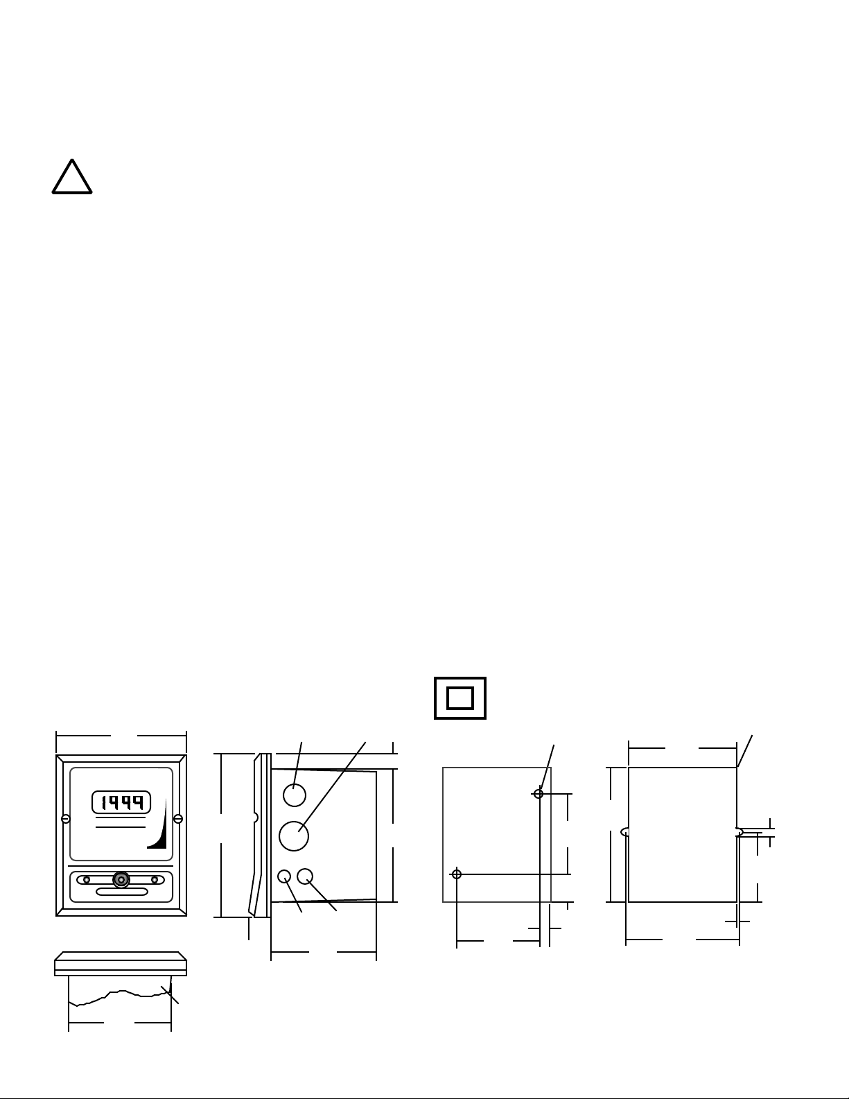
3. PANEL MOUNTING
A panel mounting fastening kit is provided with all
Monitor/controllers. Panel mounting will require the use of the
fastening kit's two (2) 4-40 mounting screws/nuts or two (2) #4 x
1/2" sheet metal screws. See figure II.B.1. for panel cutout
dimensions.
1. Select your mounting location. Mark the appropriate
panel cutout and complete the necessary panel cut.
2. Carefully unfasten and separate the Monitor's front panel
from its enclosure.
3. Disconnect all panel cable(s)/wires from the Monitor's
Control board.
DOUBLE INSULATED
0.31 DIA, X2
(8)
0.53
(14)
0.13 RAD MAX, X4
(3)
3.96
(101)
750 II
MICROSIEMENS / CM
SET POINT
3.89
(99)
5.00
6.00
(152)
MYRON L
COMPANY
HIGHLOW
0.63 THK
(16)
0.50 DIA
(13)
0.75
(19)
Figure II.B.1.
0.60 DIA
(15)
3.78
(96)
4.94
(126)
SURFACE AND PANEL MOUNTING DIAGRAMS
SURFACE
MOUNT
3.10
(79)
NOT TO SCALE
DIMENSIONS IN INCHES
(MILLIMETERS)
2.84
(72)
1.05
(27)
0.40
(10)
(127)
PANEL
CUTOUT
4.17
(106)
0.113
(3)
2.54
(64)
0.11
(3)
9
Page 13
4. Slide the enclosure through the panel cutout
until its flange contacts the panel.
5. Insert mounting screws through the flange
mounting holes and tightly secure.
6. Reconnect all panel cable(s)/wires and resecure the front panel.
C. OEM MECHANICAL INSTALLTION
This section provides the recommended procedures for properly
installing the OEM 750 Series II Conductivity/Resistivity
Monitor/controller.
NOTE: Mounting of the OEM monitor/controller circuit board is
left up to the OEM. It is recommended that the following be noted
and observed.
1. CIRCUIT BOARD
Total heigth of CB is 1.40” (36mm).
The circuit board has four .175” (4.4 mm) holes for mounting. The
centers are 3.10” (78.7 mm) x 4.10” (104.1 mm) see figure II.C.1.
CB must be mounted on at least .250” (6.35 mm) standoffs to
prevent shorting to metal chassis (standoffs user supplied).
CB must be mounted in a clean and dry environment.
Allow working room for inserting wires, testing and calibration.
Indicator lights and switches require 1/4” (6.35mm) holes.
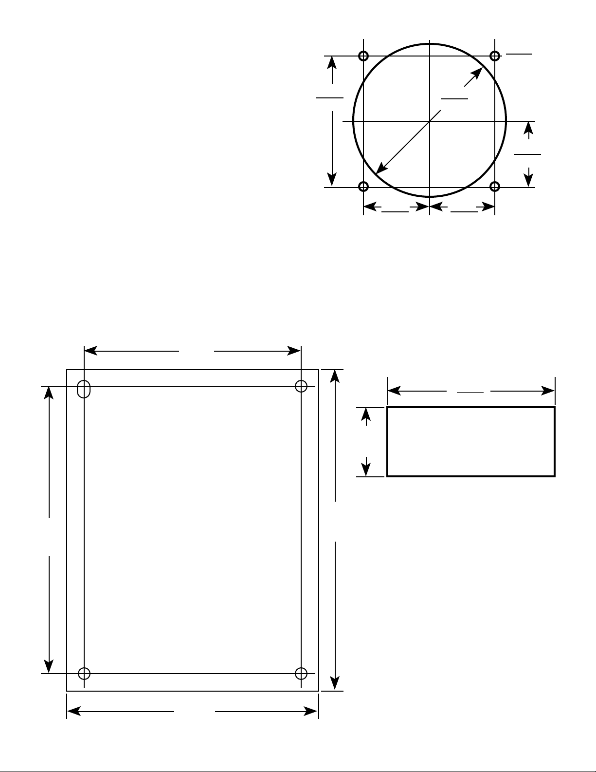
1.880
(47.75)
2.218 Dia.
56.34
.940
Analog Meter Hole Pattern
Figure II.C.2
2. METER MOVEMENT
Refer to figure II.C.2 for dimensions.
1. Cut opening in user panel.
2. Drill four holes at locations as shown.
3. Install meter movement using supplied hardware.
.125 X4
(3.125)
.940
(23.88)
.940
(23.88)(23.88)
4.100
(104.1)
3.100
(78.74)
Figure II.C.1
2.390
(60.71)
.980
(24.89)
Digital Display Cutout Pattern
Figure II.C.3
4.585
(116.5)
3. DIGITAL DISPLAY
Refer to figure II.C.3 for dimensions.
1. Cut opening in user panel
2. Install LCD with brackets supplied.
3.600
(91.44)
10
Page 14
D. SENSOR INSERTION/IMMERSION MOUNTING
11
E. ELECTRICAL INSTALLATION
The electrical installation procedures provided in this manual are
common to all Conductivity & Resistivity Monitor/controllers. See
figure II.B.1. for the hole dimensions of the enclosure's cable
access holes. Unless otherwise instructed, refer to figure II.E.1.
for the 750 Series Monitor's terminal block connector wiring
designations.
NOTE: After removing an enclosure's access hole cutout, it is
suggested that the user mount a watertight restraint fixture prior
to installing a cable.
!
WARNING !
The Sensor’s mounting orientation must provide a continuous and
adequate circulation flow to prevent the trapping of air bubbles
within the Sensor’s electrode area (CS51 shown in figure II.D.1).
Failure to do so will result in conditions that will prevent the Sensor
from functioning properly.
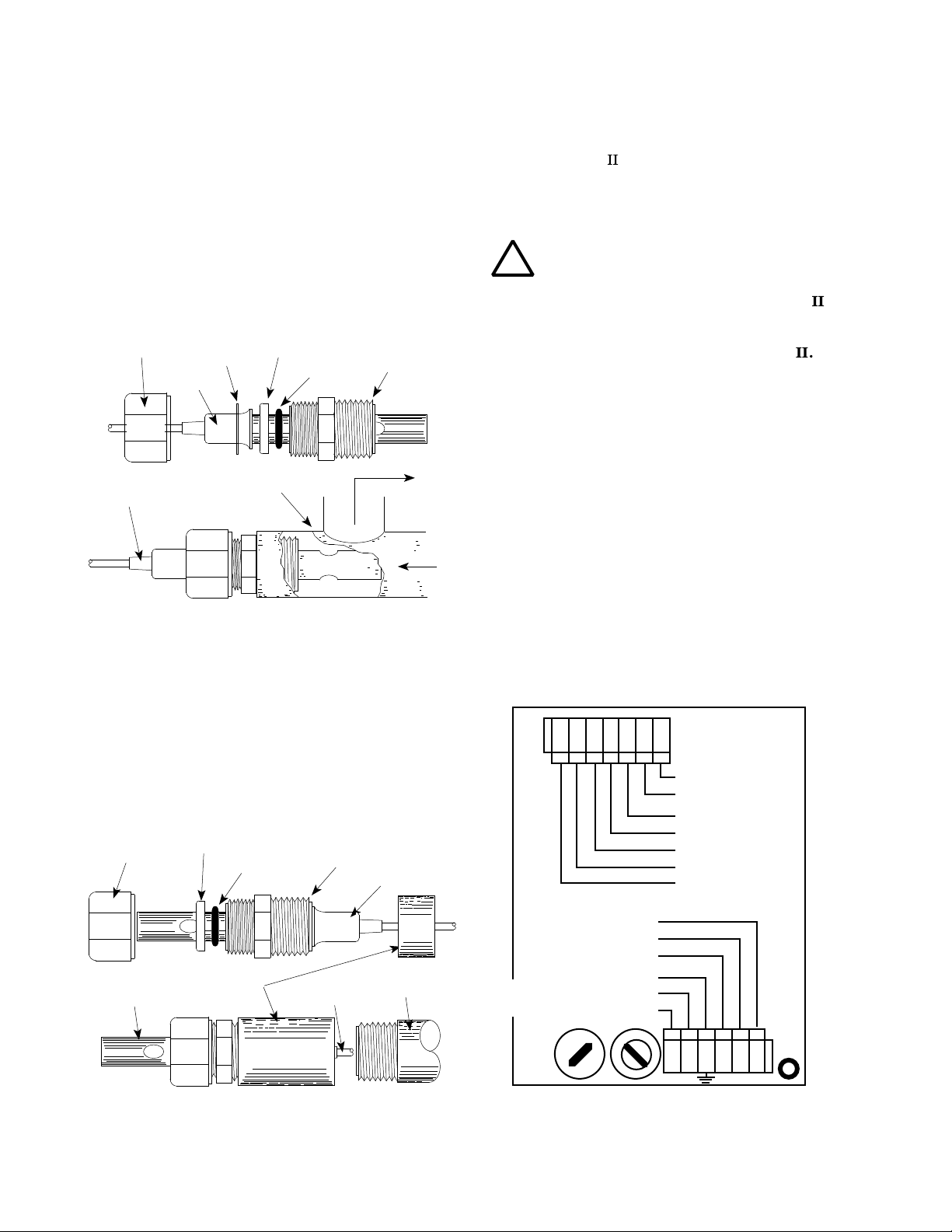
1. INSERTION MODE (in-line installation)
Use approved sealant, i.e. Teflon tape as required.
1. Verify that the Sensor’s Fitting assembly is properly
assembled as shown in figure II.D.1.
2. Insert the Sensor Fitting assembly into the "T" fitting with
electrode aligned as shown in figure II.D.1. and tightly
secure.
SECURING NUT
FLANGE
CABLE
INSERTION MODE ASSEMBLY
SS
WASHER
"T" FITTING
PLASTIC
WASHER
O-RING
THREADED FITTING
3/4" FNPT
OUT
IN
Figure II.D.1
2. IMMERSION OR DIP SENSOR ASSEMBLY
Use approved sealant, i.e. Teflon tape as required.
A device to disconnect the Model 750 from the
power supply is required. It is recommended that this
switch or circuit breaker be labeled as the
disconnection device for the Model 750
1. MAIN INPUT POWER INSTALLATION
WARNING: All AC line powered Monitor/controllers
are factory set for 115 VAC. Before starting, ensure
the input power “115/230” selection is correct for
your requirements. Failure to do so is beyond the
responsibility of the Myron L Company. See section
II.E.2. below and figure II.E.1.
NOTE: Some models may have either a 24 VAC or a
24 VDC input power requirement - check labels
carefully.
For OEM models skip to step #7.
1. Verify that the main AC power source is turned "OFF " or
disconnected.
2. Using a standard slot screwdriver remove the two (2)
screws on the front panel.
3. Carefully wiggle the front panel to loosen the gasket and
pull gently toward you. Do not pull more than about 8
inches/20CM or you could damage the wiring harness.
1. Verify that the Sensor’s Fitting assembly is properly
assembled as shown in figure II.D.2.
2. Insert and pull the Sensor’s cable through the extension
tube and then tightly attach extension tube to Sensor
assembly as shown in figure II.D.2.
PLASTIC
SECURING NUT
SENSOR TIP
IMMERSION OR DIP SENSOR ASSEMBLY
WASHER
O-RING
COUPLING
3/4" NPT
THREADED FITTING
3/4" FNPT
FLANGE
EXTENSION TUBE
CABLE
Figure II.D.2
(+)
(-)
NEU
GRN
RED
WHT
BLK
{
COM
NO
NC
L N
FUSE
ALARM
CONTROL
RELAY
MAIN
INPUT
POWER
GND-GRN
NEU-WHT/-DC
{
HOT-BLK/+DC
115/230
SWITCH
ELECTRICAL CONNECT DIAGRAM
Figure II.E.1
0-10VDC
}
OUTPUT
SENSOR
}
CHASSIS GROUND for
OEM INSTALLATIONS ONLY
Page 15
4. Turn the front panel around so that the back side is
Y
facing you and set aside for now.
5. Carefully remove front panel, leaving the harness
connected.
6. Using the enclosure cutouts, install the proper wire and
watertight cable restraint (not provided) to comply with
local electrical codes.
7. Neatly connect wires to the Main Circuit Board
connectors, as shown in figure II.E.1.
*CAUTION: The input power connectors require only a small
screwdriver or a pen to push on the release levers. The release
levers may be broken or damaged if not pushed straight toward
the circuit board. DO NOT push the release levers sideways.
2. 115/230 VAC CONVERSION
1. Before turning power on to the Monitor/controller ensure
the proper input voltage has been selected. Failure to do
so will blow the fuse. It could, under some conditions,
cause injury and damage the instrument voiding the
warranty.
2. Locate switch located next to the fuse holder.
3. Using a screwdriver, turn switch to required voltage.
3. CONNECTING THE SENSOR CABLE
For OEM models skip #1.
1. Place the Sensor’s interface cable and user supplied
watertight cable restraint into the enclosure's
appropriate access hole.
2. Install the sensor cable wire to comply with local
electrical codes. Follow the color code as marked. See
figure II.E.1.
*CAUTION: The sensor connectors require only a small
screwdriver or a pen to push on the release levers. The release
levers may be broken or damaged if not pushed straight toward
the circuit board. DO NOT push the release levers sideways.
Requirements:
For Conductivity/TDS; one 10k
may be ordered from the Myron L Company.
For Resistivity; one 100k
resistor, user supplied or may be ordered from the Myron L
Company.
NOTE: When opening instrument, remove front cover with care; a
ribbon cable connects the front panel and main board. If the front
panel has all ready been removed from the enclosure skip to #4.
1. Using a standard slot screwdriver remove the two (2)
screws on the front panel.
2. Carefully wiggle the front panel to loosen the gasket and
pull gently toward you. Do not pull more than
about 8 inches/20CM or you could damage the wiring
harness.
3. Turn the front panel around so that the back side is
facing you and set aside.
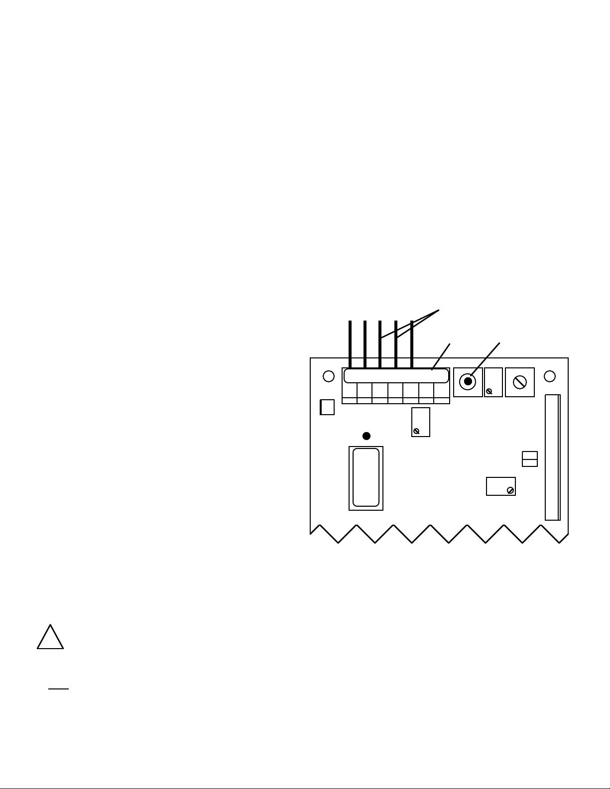
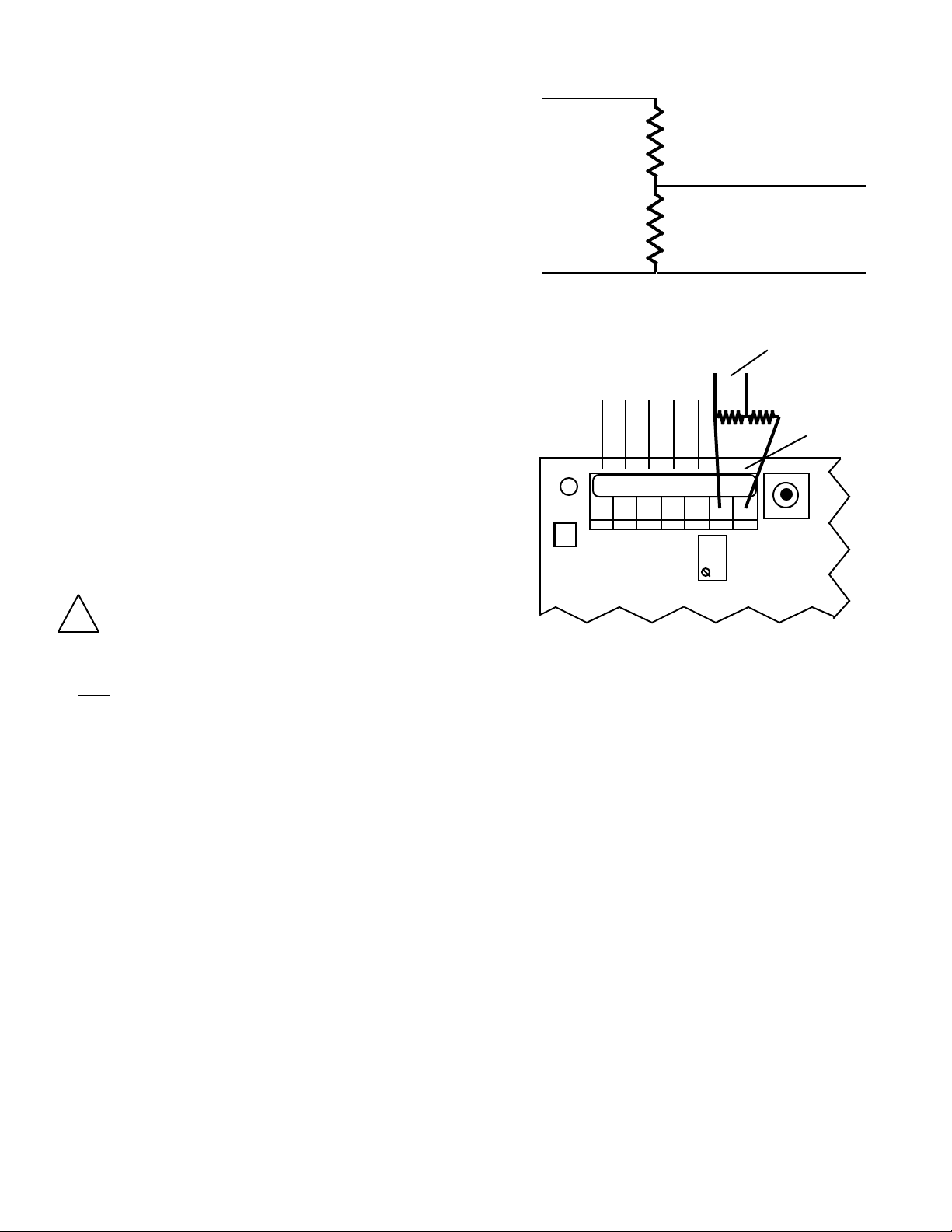
4. For Conductivity/TDS Monitor/controllers;
a. If sensor is installed, locate and remove the RED
(RD) and the GREEN (GN) leads from MAIN
Circuit Board, as shown in figure II.E.2.
b. Cut off or tape RED (RD) and the GREEN (GN) leads
from sensor.
SENSOR LEADS
BK WT RD GN NU R- R+
3S
1% resistor, user supplied or
1% resistor, and one 5.49K 1%
REMOVE THESE TWO LEADS
0-10VDC
OUTPUT
FULL SCALE
PUSH TO TEST
HYS1SP1FS SW
a. MODIFICATION FOR US PHARMACEUTICAL
25 (No Temperature Compensation)
This simple modification will allow your Monitor/controller to meet
the USP 25 requirements by defeating the normal temperature
compensation circuit thus giving “uncompensated” readings as
required.
Specifications:
As required to meet USP25.
Installation
Briefly For Conductivity/TDS, a resistor is installed in place of the sensor
“temperature” sensing leads.
For Resistivity, two resistors are installed in place of the sensor
“temperature” sensing leads.
The extra sensor leads are either cut off or the ends are wrapped
in tape to prevent shorting.
CAUTION - READ FOLLOWING CAREFULL
!
WARNING: BEFORE STARTING, IF MONITOR/
CONTROLLER IS INSTALLED, ENSURE THE POWER
IS OFF. FAILURE TO DO SO COULD CAUSE DAMAGE
TO THE INSTRUMENT, AND COULD BE HARMFUL OR
FATAL TO PERSONNEL. ONLY QUALIFIED
PERSONNEL SHOULD INSTALL OR SERVICE
ELECTRICAL EQUIPMENT.
CAL
}
UP
INC
DIS
-121
2000µS
Conductivity/TDS Main CB Assembly
Figure II.E.2
c. Install 10k
(GN) connector locations, as shown in figure
II.E.3.
For Resistivity Monitor/controllers;
a. If sensor is installed, locate and remove the
GREEN (GN), RED (RD), and the NEUTRAL (NU)
leads from MAIN Circuit Board, as shown in figure
II.E.4.
b. Cut off or tape GREEN (GN), RED (RD), and the
NEUTRAL (NU) leads from sensor.
c. Install 100k
(GN) connector locations, as shown in figure
II.E.5.
resistor at RED (RD) and the GREEN
resistor at BLACK (BK) and GREEN
SPC
DEC
12
Page 16
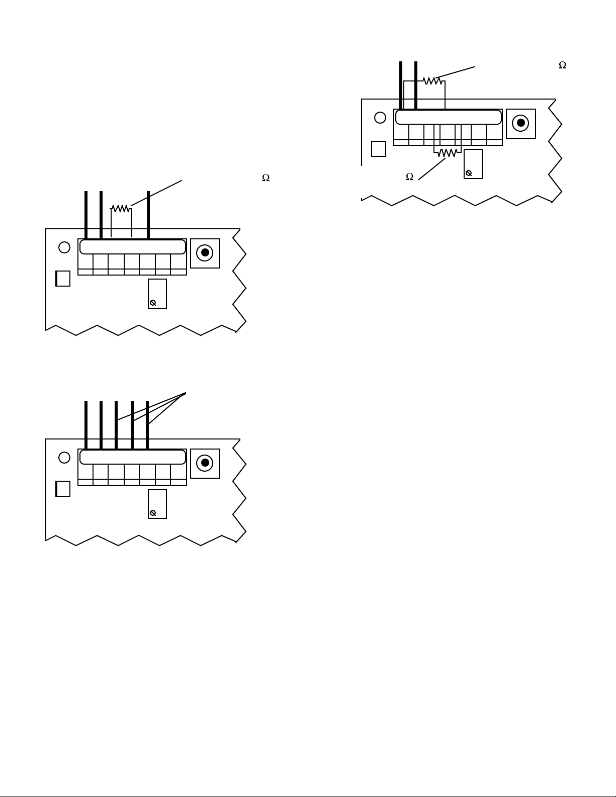
d. Install 5.49kΩ resistor at RED (RD) and the
NEUTRAL (NU) connector locations, as shown in
figure II.E.5.
5. Carefully reinstall the front panel, bottom first. Ensure no
wires have been pinched between enclosure and front
panel.
6. Reinstall the two (2) screws and tighten.
7. To operate, turn power ON.
NOTE: Recalibration will require both the solution and sensor be
at 25°C for maximum accuracy.
SENSOR LEADS
INSTALL 100K
RESISTOR HERE
BK WT RD GN NU R- R+
3S
FS SW
SENSOR LEADS INSTALL 10K
RESISTOR HERE
BK WT RD GN NU R- R+
3S
FS SW
CAL
Conductivity/TDS Main CB Assembly
Figure II.E.3
SENSOR LEADS
REMOVE THESE
THREE LEADS
BK WT RD GN NU R- R+
3S
FS SW
CAL
Resistivity Main CB Assembly
Figure II.E.4
4. SOLID STATE OUTPUT
24 VDC Unregulated 30mA max. The following instructions are
assuming the Monitor/controller enclosure is already open.
a. Piezo Electric Alarm - PA/PAO (option)
For additional information, see Piezo Alarm under Options in
section III.I.
1. If not already installed, peel tape backing from PIEZO
and press into place per figure III.I.3.
2. Attach connector to main control circuit board per figure
III.I.4.
NOTE: If remotely mounted; cut wires and splice as necessary,
use comparable wire. Piezo requires 1/4” (6.35mm) hole in user
panel.
INSTALL 5.49K
RESISTOR HERE
CAL
Resistivity Main CB Assembly
Figure II.E.5
b. Remote Alarm - RA™ (option)
For additional information,see RA Instructions under options in
section III.J.
1. Run user supplied #22, 2 conductor speaker type wire
from Monitor/controller to RA location as necessary.
Additional wire may be ordered, part #RAW-200, see
Options & Accessories.
2. Open the RA by removing the four screws.
3. Locate and remove the 8” 2 conductor wire attached to
RA.
4. At the controller, connect the extension wires to the 8”
2 conductor wire with the wire nuts provided — Black to
Positive (+) and White to Negative (-). Be sure to first
pass the wire through the user supplied waterproof strain
relief in the enclosure.
5. Plug the reddish brown female connector into the male
connector on the controller CB marked either RA or PA
(see inside case label for location). It will only go on the
connector one way.
6. At the RA, connect the wires to the connector — Black
to Positive (+) and White to Negative (-).
7. To test, simply turn on the controller and adjust controller
set point until the alarm/piezo sounds off. If controller is
not yet connected to a functioning sensor, on
conductivity/TDS controllers it will be necessary to press
and hold the Full Scale test switch.
The black button on the front of the RA will mute the
piezo alarm for approximately three minutes or until you
improve the water quality (readjust controller set point).
The piezo alarm will continue to sound off every three
minutes until the user has improved the alarm condition
inside the controller. If three minutes muting is fine for
your application, skip to step 9.
8. If three minutes is too long or too short, adjust time delay
control inside RA until desired mute time is achieved
adjustable from approximately 6 seconds to 10 minutes).
9. Replace the bottom of the RA, and secure RA to the
surface you have selected for its installation.
NOTE: If the RA does not sound off;
1. Check the polarity of the extension wire connections.
2. Be sure the controller is actually switching (relay will
click).
13
Page 17
c. Connect to your own alarm or ?
Use the following as guidelines.
Connector is a standard 2 wire Methode* style
connector. Connector with 8” wires, part #RAH, is
available from the Myron L Company.
Ensure your requirements do not exceed the 24VDC
Unregulated 30mA maximum.
Ensure the polarity is correct (RED is positive), see
figure V.A.1.
Attach wires to RA.
Attach connector to controller connector (RA) per figure
V.A.1.
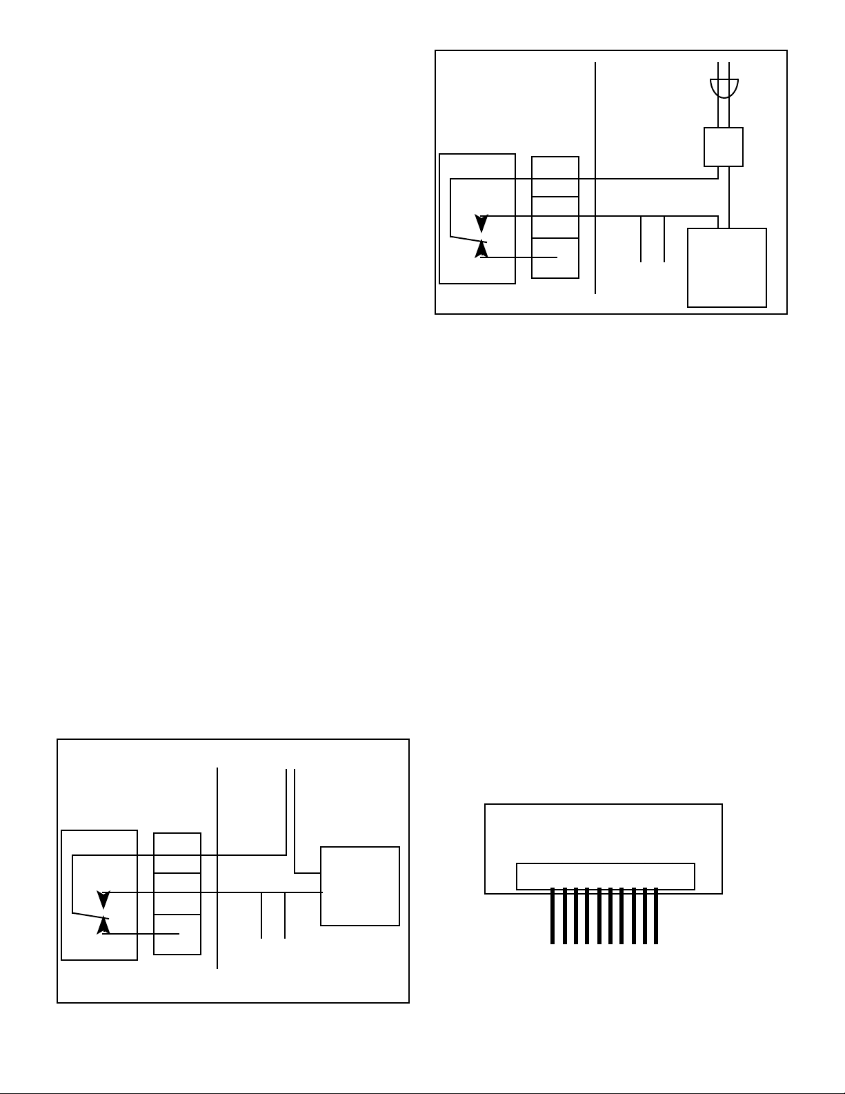
MONITOR/CONTROLLER
CIRCUIT BOARD
CM
NO
115VAC
POWER
SOURCE
115 to 24VAC
TRANSFORMER
COM
NO
X
VR
*Methode is registered trademark of Methode Electronics, Inc.
5. ALARM/CONTROL RELAY CONNECTIONS
Myron L Company Monitor/controllers are equipped with a “Dry
Contact” relay which is designed to energize/de-energize when
the set point is crossed. (See section IV.C.3) for set point
adjustment procedure) The relay energizes on increasing or
decreasing readings as set by the user, see section IV.C.1.
When energized (above set point), the Common (COM) will
disconnect from the Normally Closed (NC) contact and connect to
the Normally Open (NO) contact. Devices may be operated using
either the Normally Open contact or Normally Closed contact; or
both relay contacts may be used to control two devices of the
same voltage.
NOTE: A flow switch may be installed (electrically connected)
utilizing one of two convenient methods; the 3S connection, see
figure II.E.2, (remove jumper and connect flow switch across
terminals - 8” harness (RAH) available from the Myron L
Company), or inline with either relay connection, see figure II.E.6
or II.E.7.
WARNING: CONNECTING BOTH POWER SOURCE
LEADS TO THE RELAY TERMINAL BLOCK
CONNECTERS WILL DAMAGE THE CIRCUIT BOARD
AND MAY CAUSE PERSONAL INJURY.
1. Place the user supplied Alarm relay interface cable and
watertight cable restraint into the enclosure's
appropriate access hole. Skip for OEM.
2. Neatly connect the relay interface cable wires to the
Monitor/controller's terminal block connectors, see
figures II.E.1, II.E.6 or II.E.7.
POWER
MONITOR/CONTROLLER
CIRCUIT BOARD
SOURCE
DEVICE
RELAY
NC
RELAY
TERMINAL BLOCK
OPT.
FLOW
SWITCH
TO BE
CONTROLLED
Figure II.E.7
CAUTION: The connectors require only a small screwdriver or a
pen to push on the release levers. The release levers may be
broken or damaged if not pushed straight toward the circuit board.
DO NOT push the release levers sideways.
The easiest method of connecting the relay is shown in figures
II.E.1, and II.E.6. These show how the dry contact relay can use
incoming power to activate a controlled device (alarm, solenoid
valve, etc.) of 10 amps or less.
For 24 VAC applications, the Myron L Company offers a 115 VAC
to 24 VAC transformer, Model #VR, see figure II.E.7. Other
voltages must be user-supplied.
6. CONNECTING DISPLAY HARNESS TO DISPLAY
If the installation required the removal of the display harness from
the display (OEM installation requires connection), the following
procedure will ensure it is reinstalled without damaging the
display.
WARNING: THE DISPLAY WILL BE IRREPARABLY
DAMAGED IF THE HARNESS IS INSTALLED UPSIDEDOWN OR MISALIGNED. THE HARNESS MUST BE
INSTALLED AS SHOWN IN FIGURE II.E.8.
1. Grasp connector and align wires DOWN on display or with
the small edge of the display as shown in figure II.E.8.
2. Press connector onto display pins. Ensure pins are
aligned or they may become bent. Wiggle connector
slightly “end to end” if necessary.
RELAY
CM
NO
NC
RELAY
TERMINAL BLOCK
Figure II.E.6
COM
NO
X
OPT.
FLOW
SWITCH
DEVICE
TO BE
CONTROLLED
DISPLAY
DISPLAY CONNECTION
DISPLAY
HARNESS
PANEL MOUNTED DISPLAY
REAR VIEW
Figure II.E.8
14
Page 18
F. 0-10 VDC RECORDER OUTPUT
The 0-10 VDC output is designed to give the user the capability of
sending a signal to a remote meter, recorder, PLC or SCADA
system.
1. CONNECTION
1. Place the user supplied interface cable and watertight
cable restraint into the enclosure's appropriate access
hole. Skip for OEM.
2. Connect the Recorder's plus (+) and minus (-) terminal
wires to the Recorder output connectors. (See figure
II.E.1.)
3. Refer to Section V.C.1.b for the procedures to calibrate
the 0-10 VDC voltage output.
+
0-10V Output
-
A
B
Figure II.F.1
+
Recording
Device
-
2. VOLTAGE DIVIDER
A voltage divider gives the user the ability to scale or tailor the
output to a particular need or requirement due to the input of
another device, i.e. the output of the Main CB is 0-10V while the
input requirement of a particular recording device is 0-5V.
a. INSTALLATION
Briefly—
Two resistors are installed across the 0-10V output.
The output is recalibrated to required voltage.
Requirements
Select two (2) resistors as listed;
For 0-5V Output both "A & B" are 2K Resistors.
For 0-1V Output "A" is a 9K resistor and "B" is a 1K resistor.
CAUTION - READ FOLLOWING CAREFULLY
!
WARNING: BEFORE STARTING, IF MONITOR/
CONTROLLER IS INSTALLED, ENSURE THE POWER
IS OFF. FAILURE TO DO SO COULD CAUSE DAMAGE
TO THE INSTRUMENT, AND COULD BE HARMFUL OR
FATAL TO PERSONNEL. ONLY QUALIFIED
PERSONNEL SHOULD INSTALL ELECTRICAL
EQUIPMENT.
Physical
If the front panel has all ready been removed from the enclosure
skip to #3.
1. Using a standard slot screwdriver remove the two (2)
screws on the front panel.
2. Carefully wiggle the front panel to loosen the gasket and
pull gently toward you. Do not pull more than about 8
inches/20CM or you could damage the wiring harness.
3. Turn the front panel around so that the back side is
facing you and set aside for now.
4. Solder two selected resistors together as shown in figure
II.F.1.
5. Attach leads to recording device as shown in figure
II.F.1.
6. Attach resistors to 0-10V Output as shown in figure
II.F.2.
Ensure resistors and leads DO NOT short to each other
or to any part of the CB assembly.
7. Recalibration is required, see Calibration Procedures,
section V.C.
NEW
OUTPUT
AS
SENSOR LEADS
BK WT RD GN NU R- R+
3S
- +
SELECTED
0-10VDC
OUTPUT
FS SW
CAL
Main CB Assembly
Figure II.F.2
Reassembly
1. Carefully reinstall the front panel, bottom first, ensure no
wires have been pinched.
2. Reinstall the two (2) screws and tighten.
3. To operate, turn power ON.
15
Page 19
G. RE-RANGE YOUR MONITOR/CONTROLLER
!
(Range Module Installation)
1. DESCRIPTION
The 750 Series II Monitor/controllers have been designed for
easy field re-rangeability. The Range Module consists of a 16 pin
Header that plugs into a 16 pin socket.
For available ranges, see Range Selection Guide I.G. When
making large range changes, i.e. 5000 ppm to 50 ppt, a different
sensor may also be required as noted in the Range Selection
Guide. Order Range Module by adding the prefix “RM” to the range
number as in examples below.
Conductivity/TDS Range Modules —
RMXXX i.e. = RM121 is a 0-2000µS
Resistivity Range Modules —
RMXX i.e. = RM11 is a 0-20MΩ
NOTE: Some OEM models may not be re-ranged being originally
manufactured with a fixed range. If your application requires reranging an OEM model, first contact the system manufacture for
help. The Myron L Company may re-range or exchange your
instrument at a cost.
screws on the front panel.
2. Carefully wiggle the front panel to loosen the gasket and
pull gently toward you. Do not pull more than about 8
inches/20CM or you could damage the wiring harness.
3. Turn the front panel around so that the back side is
facing you and set aside.
4. Locate and remove existing Range Module from MAIN
Circuit Board, as shown in figure II.G.1. It is not easy to
remove, it was designed to stay in place under adverse
conditions.
5. With the pointer up, carefully align the new Range Module
to the socket on the MAIN Circuit Board as shown in
figure II.G.1.
6. Press firmly into place.
7. For analog models, add multiplier label to front panel. See
figures II.G.10 and II.G.11 for suggested locations. In
some cases changing the meter scale will be necessary.
See Changing Analog Meter Scale, section II.G.3.
8. Recalibrate, see CALIBRATION PROCEDURES, section
V.C.
0-10VDC
OUTPUT
BK WT RD GN NU R- R+
FULL SCALE
PUSH TO TEST
2. INSTALLATION
Briefly The new Range Module simply replaces the Range Module
presently installed, see figure II.G.1.
Multiplier label is added to analog models*.
Type label may be required if changing from Microsiemens to
Millisiemens or PPM/PPT.
The Full Scale reading is recalibrated.
IMPORTANT NOTES:
1. When changing ranges on Digital Monitor/
controllers with the -45 option (4 1/2 digit backlit
display), the following modifications may be required
to the range module; RM123 thru 128 and RM16
require pin number 9 be removed or bent toward the
side, see Fig. II.G.2. On RM117 thru 122 a jumper
wire must be soldered to the RM, see Fig. II.G.3.
*2. Analog Monitor/controllers may require a scale
change. See section II.G.3 for the specific
instructions.
POINTER
CAUTION - READ FOLLOWING CAREFULLY
WARNING: BEFORE STARTING, IF MONITOR/
CONTROLLER IS INSTALLED, ENSURE THE POWER
IS OFF. FAILURE TO DO SO COULD CAUSE DAMAGE
TO THE INSTRUMENT, AND COULD BE HARMFUL OR
FATAL TO PERSONNEL. ONLY QUALIFIED
PERSONNEL SHOULD INSTALL OR SERVICE
ELECTRICAL EQUIPMENT.
Physical
NOTE: When opening instrument, remove front cover with care;
a ribbon cable connects the front panel and main board. If the
front panel has already been removed from the enclosure skip to
#4.
1. Using a standard slot screwdriver remove the two (2)
3S
REMOVE
PIN #9
Figure II.G.2
FSSW
CAL
}
UP
RANGE
-121
TRANSFORMER
115/
230
UP
MONITOR/CONTROLLERS ONLY
MODULE
2000µS
751 756
752 757
753 758
754 759
MYRON L
COMPANY
FUSE*
AC C GD NC NO CM
Main CB Assembly
Figure II.G.1
ADD JUMPER
CONNECTING
PINS 7 & 10
RANGE MODULE
Bottom View
DIGITAL 4 1/2 DIGIT LCD
HYS1SP1
SPC
INC
DIS
DEC
SECOND RELAY
REMOVE TO INSTALL
CHS
UP
Figure II.G.3
16
PA RA
GND
Page 20
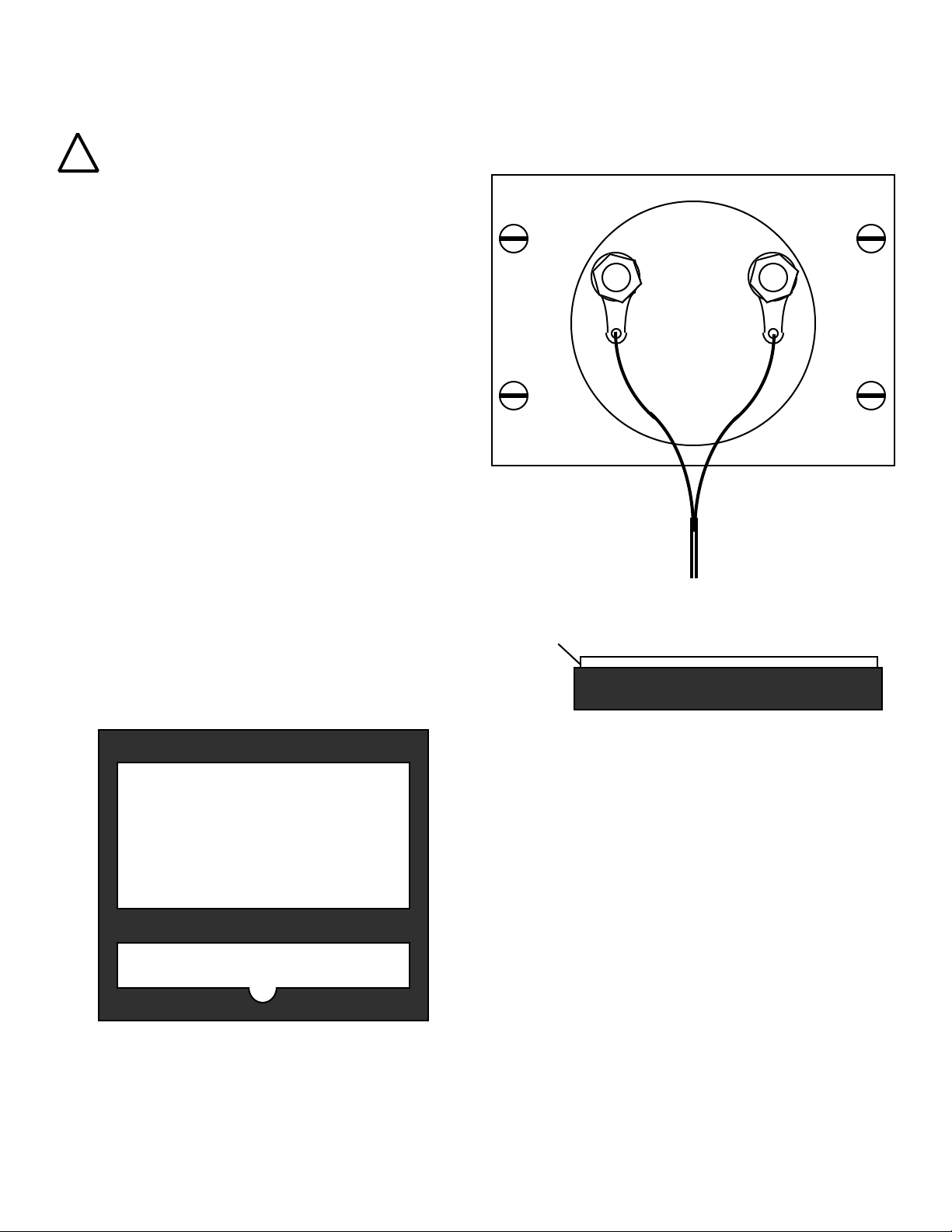
3. CHANGING ANALOG METER SCALE (DIAL)
!
After changing ranges on an analog model 750II it may be
necessary to change the meter scale (dial). The following steps
will guide you through the change. Please read caution carefully.
CAUTION - READ FOLLOWING CAREFULLY
screws holding the scale (dial). See figure II.G.7.
6. To remove the scale, lightly press on bottom of scale,
the top will lift up. Be extremely careful not to bend the
pointer (needle) or to move the Zero Adjust (ZA).
See figure II.G.7.
Exercise extreme caution while working on meter.
Meter movement, and/or pointer (needle) may be
damaged beyond repair. It is recommended only
qualified personnel change scales.
DO NOT allow dust to enter the case while it is open.
Failure to follow these instructions may cause
irreparable damage, and will VOID the warranty.
Briefly The meter is removed from front panel (except OEM models).
The cover is removed.
The hexscrews retaining the scale are removed, and scale
is slid out the top.
New scale is slid in place, and screws reinstalled.
Cover aligned, installed and zero set.
Physical
For OEM models skip to #4.
1. Using a wrench, nut driver or pliers remove the two (2)
large nuts retaining the circuit board wiring harness
connectors. Red wire is PLUS (+),
Brown wire is MINUS (-). See figure II.G.4.
2. Using a standard slot screwdriver remove the four (4)
screws, and the backing plate holding the meter to the
front panel as shown in figure II.G.4.
3. Remove meter. Do not lose the gasket between the
meter and the front panel it must be reinstalled upon
reassembly. See figure II.G.5. Align gasket to front
panel so as the gasket does not show when meter is
assembled to front panel.
Backing Plate
Mounting Screws (4)
+
METER
BROWN WIRERED WIRE
Harness to Main
CB Connector
Figure II.G.4
Pry Here Carefully
CLEAR COVER
GASKET
Figure II.G.5
4. Using a wide blade standard slot screwdriver, starting at
a bottom corner, CAREFULLY pry the clear plastic cover
loose from the movement case. See figure II.G.6.
5. Using a 1/8” (3.2mm) hexdriver, remove the two (2) small
CASE
Figure II.G.6
7. Grasp top and slide scale slowly out from top. Be
extremely careful not to bend the pointer (needle) or to
move the Zero Adjust (ZA). See figure II.G.7.
8. Reverse the above procedure using the new scale.
NOTE: While replacing the clear plastic cover, ensure the
ZA screw pin on the cover aligns with the inverted “Y” shaped
slot on the meter movement. See figure II.G.7.
IF, the inverted “Y” shaped slot is inadvertently moved -
BEFORE installing cover:
a. Recenter the inverted “Y” to the meter case as
shown in figure II.G.7.
b. Center the Zero Adjust (ZA) PIN on the clear
plastic cover as shown in figure II.G.8.
9. Using a standard slot screwdriver, ensure the ZA is
operating - pointer swings left and right when turning the
ZA with a standard slot screwdriver. See figure II.G.9.
10. Set Meter ZERO as shown in figure II.G.9.
11. Reinstall meter to front panel, reversing steps 1-3
(except OEM models).
17
Page 21

Grasp Scale Here
and Slide Out TOP
SCALE (dial)
Align Pointer with FIRST Line
0
0
Pointer (needle)
1/8" (3.18mm)
Hex Screws (2)
Press
Lightly
Here
METER CASE
Inverted "Y"
Figure II.G.7
4. LABEL CHANGE
Since you have re-ranged your Monitor/controller it may be
necessary to relabel it. If you made any one of the following
changes it will be necessary to “add or change” the designator
label on the Front Panel. Pick the correct label and apply to the
Front Panel as shown in figure II.G.10. If there is an overlay label
already in place remove it and clean the surface with isopropyl
alcohol (rubbing alcohol) before installing the new label. A clean
surface will allow the new label to adhere to the surface better.
1. Did you change from µS to mS, PPM or PPT?
2. Did you change from mS to µS, PPM or PPT?
3. Did you change from PPM to PPT, µS or mS?
4. Did you change from PPT to PPM, µS or mS?
5. Do you need to install a Multiplier label as in figure
II.G.11.
CLEAR PLASTIC COVER
(case not shown for clarity)
Multiplier Label
(X1000 example)
FRONT PANEL
ZERO ADJUST
under rubber plug.
Figure II.G.10
Zero Adjust (ZA)
Figure II.G.9
MICROSIEMENS / CM
750II
SET POINT
X1000
MYRON L
COMPANY
HIGH
LOW
HIGHLOW
CENTER Zero Adjust (ZA) PIN
CLEAR PLASTIC COVER
(Inside View)
Figure II.G.8
REASSEMBLY
1. Carefully reinstall the front panel, bottom first, ensure no
wires have been pinched.
2. Reinstall the two (2) screws and tighten.
3. To operate, turn power ON.
SCALE (dial)
0
Multiplier Label
(X1000 example)
X1000
OEM ANALOG METER
Figure II.G.11
18
Page 22
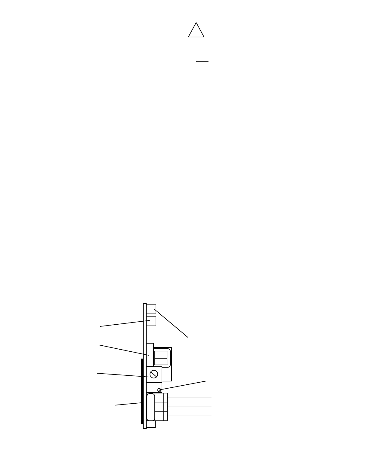
III. OPTIONS &
ACCESSORIES
A. SC/SCO MODULE
(SECOND ALARM/CONTROL OPTION)
(Digital & OEM Models ONLY)
-SC Second Alarm Control Module ordered with
Monitor/controller.
SCO Second Alarm Control Module Kit ordered separately.
1. DESCRIPTION:
An essential component for applications requiring a DUAL
setpoint. The Second Alarm/control module allows the user
additional flexibility by being able to sound TWO Alarms, and
Control TWO functions with the second 10 amp relay.
The set points are non-overlapping. The #2 alarm/control (HIGH
set point) rides on top of the #1 alarm/control (LOW set point).
SCO kit comes with all items necessary to install and operate: SC
Module, front panel harness with LED, switch, bezel, cap and two
o-rings (006 & 008); and replacement lower front panel label
(L2ALARM).
Specifications:
Control Function:
Setpoint control continuously adjustable 0-100% of span
Hysteresis:
Adjustable from 0.3-3% of full scale
Indicators:
Above (red) and below (green) setpoint LEDs (reversible)
Relay Contact Rating:
SPDT 10 amp ~ 250 VAC, 30 VDC. Relay operates
increasing or decreasing reading (selectable)
Solid State Output:
Powered — 24VDC 30mA Maximum
2. INSTALLATION:
Briefly The Second Alarm/control module plugs into the main
Monitor/controller circuit board.
The LED/switch harness is installed into the front panel.
Set point and hysteresis are set per “your“
requirements.
If this option is installed, skip to III.A.2.a.
SET POINT #2
CONVERSION
PA
CAUTION - READ FOLLOWING CAREFULLY
!
WARNING: BEFORE STARTING, IF MONITOR/
CONTROLLER IS INSTALLED, ENSURE THE POWER
IS OFF. FAILURE TO DO SO COULD CAUSE DAMAGE
TO THE INSTRUMENT, AND COULD BE HARMFUL OR
FATAL TO PERSONNEL. ONLY QUALIFIED
PERSONNEL SHOULD INSTALL OR SERVICE
ELECTRICAL EQUIPMENT.
Physical
If the front panel has all ready been removed from the enclosure
skip to #3.
MAIN Circuit Board
1. Using a standard slot screwdriver remove the two (2)
screws on the front panel.
2. Carefully wiggle the front panel to loosen the gasket and
pull gently toward you. Do not pull more than
about 8 inches/20CM or you could damage the wiring
harness.
3. Turn the front panel around so that the back side is facing
you and set aside for now.
4. Remove BLACK JUMPER from MAIN Circuit Board
connector located next to the transformer as shown in
figure III.A.2.
NOTE: Do not lose BLACK JUMPER. It must be reinstalled if
second relay is removed for any reason and the #1 relay
is expected to operate.
5. Carefully press the SCO Second Alarm/Control Module
into MAIN Circuit Board as shown in figure III.A.4.
When fully seated the SCO Module will snap into place.
6. Connect the Solid State output to PA or user supplied
24VDC/30mA alarm/valve or ??, and/or control wires
to relay #2, as required, see figure III.A.4*.
a. Place the control cable and user supplied
watertight cable restraint into the enclosure's
appropriate access hole.
b. Neatly connect the control wires to the
Monitor/controller’s appropriate connectors. See
figure III.A.4.
*CAUTION: The relay connectors require only a small
screwdriver or a pen to push on the release levers. The release
levers may be broken or damaged if not pushed straight. DO NOT
push the release levers sideways.
LED/SWITCH
HARNESS
SET POINT #2
HYSTERESIS
RUBBER TAPE
(DO NOT REMOVE MUST BE IN PLACE
TO PREVENT SHORT)
SPC
INC
CM NO NC
SOLID STATE OUTPUT (24VDC 30mA)
PIEZO ELECTRIC ALARM - PA™ OR
REMOTE ALARM - RA™ OR
CUSTOMER CONNECTION
OPTIONAL SECOND ALARM/CONTROL MODULE
Figure III.A.1
SET POINT #2 (high)
ADJUST
NC
NO
COM
}
RELAY #2
19
Page 23

Front Panel
WARNING: there are two (2) o-rings installed on the switches,
one (1) on the shank and the other is under the push button. Both
of these o-rings must be reinstalled to maintain IP64/NEMA 3
ratings. See figure III.A.3.
1-4 assumes this is a conversion from a single alarm/control.
Skip to #5 if new installation or assembly.
1. Carefully remove the RED LED from the front panel by
pulling lightly on the wires. It may be necessary to use a
small flat screwdriver to slightly spread the retaining
ring.
2. Remove the set point switch from the front panel by
rotating the round bezel nut CCW on the front panel, see
figure III.A.4.
3. Remove the LOWER front label.
4. Clean off remaining adhesive, if possible with alcohol.
5. Install DUAL alarm LOWER label, P# L2ALARM.
6. Install the SCO Second Alarm/Control RED LED in the
UPPER position as shown in figures III.A.5 & III.A.6.
FULL SCALE
PUSH TO TEST
BK WT RD GN NU R- R+
3S
SET POINT #1 (low)
ADJUST
HYS1SP1FS SW
7. Install the SCO Second Alarm/Control Set Point Switch
in the UPPER center position.
8. Re-install #1 (original) Set Point Switch in the LOWER
center position.
9. Re-install the #1 (original) RED LED in the LOWER
position.
10. The GREEN LED stays in the same location.
a. Set Point Conversion (SPC) /
Reversing Set Point
The alarm/control circuit(s) on all 750 Series II Conductivity/TDS
Monitor/controllers are configured to trigger the alarm relay as the
Conductivity/TDS reading increases.
NOTE: On Resistivity Monitor/controllers the reverse is true, as
the reading decreases the alarm/control will trigger/sound.
If the user's application requires it, the alarm/control circuit may
be easily reconfigured to trigger the alarm/control relay as the
Conductivity (or ppm) reading decreases, or increases for
Resistivity. Refer to figure III.A.4 for the locations of the SPC
jumpers referred to in this section.
SET POINT #1 HYSTERESIS
RIGHT INCREASING /
LEFT DECREASING
SWITCH
BEZEL
NUT
PUSH
BUTTON
}
UP
-121
2000µS
751 756
752 757
753 758
754 759
MYRON L
COMPANY
TRANSFORMER
115/
230
POWER
Figure III.A.2
AC NEUTRAL
{
CAL
FUSE*
AC HOT
DIS
AC C GD NC NO CM
GROUND
NC NO
INC
SPC
DEC
SECOND RELAY
REMOVE TO INSTALL
CHS
COM
PA RA
GND
}
O-RING
FRONT PANEL
Switch / O-ring Assembly
Figure III.A.3
SET POINT #1
CONVERSION
REMOVE JUMPER TO INSTALL SC/SCO
SECOND ALARM/CONTROL MODULE
SOLID STATE OUTPUT (24VDC 30mA)
PIEZO ELECTRIC ALARM - PA™ OR
REMOTE ALARM - RA™ OR
CUSTOMER CONNECTION
RELAY #1
O-RING
20
Page 24

The following instructions describe the steps for converting the
Monitor/controller. Refer to figure III.A.4 for the location of the
SPC(s) on your Monitor/controller. If unnecessary, skip to Set
Point Adjustment.
1. Ensure power is OFF.
2. Locate the SPC jumpers for the alarm to be configured,
see figure III.A.4.
3. Make a note of the current orientation of the SPC
jumpers.
4. Remove both jumpers. This is easily done by hand. Take
care not to crush the jumpers if using pliers.
5. Rotate the jumpers 1/4 turn (90°) and reinstall them on
their posts.
6. Continue with Set Point adjustment.
b. Set Point Adjustment
Set point #1 (LOW) must be adjusted BEFORE adjusting set
point #2 (HIGH).
1. Turn power ON.
2. While depressing the lower "SET POINT" switch, turn the
Set Point #1 adjustment, figure III.A.4 until the
desired set point value is indicated on the display.
3. Repeat for Set Point #2 by depressing the upper “SET
POINT” switch and adjusting the SP2 on the SC/SCO
Module as shown in figure III.A.4.
4. Turn power OFF.
5. Continue or reinstall the front panel and tightly secure
both retaining screws, see REASSEMBLY below.
SC/SCO
OPTIONAL
SECOND
ALARM/
CONTROL
MODULE
#2 RELAY
LIGHTS &
SWITCH
CONNECTOR
RUBBER TAPE
(DO NOT
REMOVE)
3S
FULL SCALE
PUSH TO TEST
BK WT RD GN NU R- R+
CAL
}
UP
-121
2000µS
751 756
752 757
753 758
754 759
MYRON L
COMPANY
TRANSFORMER
115/
230
FUSE*
SET POINT #1 (low)
ADJUST
HYS1SP1FS SW
PA
INC
AC C GD NC NO CM
INC
DIS
SPC
INC
CM NO NC
SPC
DEC
SECOND RELAY
REMOVE TO INSTALL
CHS
SET POINT #1 HYSTERESIS
RIGHT INCREASING
LEFT DECREASING
SOLID STATE (24VDC 30mA) Output
PA™ PIEZO ELECTRIC ALARM OR
RA™ REMOTE ALARM OR
CUSTOMER CONNECTION
SET POINT #1
CONVERSION
SET POINT #2 HYSTERESIS
RIGHT INCREASING
LEFT DECREASING
SET POINT #2 (high)
ADJUST
NC
NO
COM
RA
PA
GND
RELAY #2
}
SOLID STATE OUTPUT (24VDC 30mA)
PIEZO ELECTRIC ALARM - PA™ OR
REMOTE ALARM - RA™ OR
CUSTOMER CONNECTION
SET POINT #2
CONVERSION
POWER
AC HOT
AC NEUTRAL
{
GROUND
Figure III.A.4
NC NO
COM
}
RELAY #1
21
Page 25

c. Hysteresis (Dead Band) Adjustment*
The hysteresis or dead band is approximately ±3% of the set
point at full scale as it leaves the factory. Under normal (most)
conditions it will not be necessary to adjust.
However, if you desire to make an adjustment please keep the
following in mind.
The adjustment is very simple and is based on set point location.
If the set point* is in the upper 75-100% of the scale, the
hysteresis control pot should be turned fully to the right.
If the set point is in the lower portion of the scale, i.e. 5-25% of
scale, the control pot may be turned fully to the left.
If you are operating in the center, 25-75% of scale, the control pot
may be adjusted in the center.
Or the hysteresis or dead band may be adjusted to tighten the
control of a particular process.
CAUTION: Adjusting the hysteresis too narrow may cause the
alarm to fluctuate (on-off) due to flow, chemical mixing or bubbles
causing the relay to chatter. This condition is to be avoided, it
could damage your valves, pumps, etc. and will eventually
damage the relay.
* Applies to both set points.
The following is assuming the front panel is already removed and
the set points have been set, if not see “Set Point Adjustment”.
1. Turn power ON.
2. Locate the Hysteresis Control (HYS1) located next to
the Set Point #1 (SP1) adjustment - it is a single turn
pot. See figure III.A.4.
3. Adjust as described in “Hysteresis (Dead Band)
Adjustment” or as desired.
4. Press set point test switch on the front panel to verify
Hysteresis is set as desired.
5. Repeat for SCO Module. See figure III.A.4.
6. Press set point test switch on the front panel to verify
Hysteresis is set as desired.
7. Turn power OFF.
REASSEMBLY:
1. Carefully reinstall the front panel, bottom first. Ensure no
wires have been pinched between enclosure and
front panel.
2. Reinstall the two (2) screws and tighten.
3. To operate, turn power ON.
SC/SCO
Set Point
Switch
SC/SCO
LOW
Red LED
Primary/Main CB
Red LED
Primary/Main CB
Set Point Switch
FRONT PANEL
Rear View
Figure III.A.5
Green
LED
d. Second Relay Connection
1. Place the user supplied relay interface cable and
watertight cable restraint into the enclosure's
appropriate access hole.
2. Neatly connect wires to the relay connector as shown in
figure III.A.4.
e. Solid State Output Options
24VDC Unregulated 30mA max.
Same as 4. above, SOLID STATE OUTPUT.
1. Piezo Electric Alarm - PA (option)
Plug PA connector to CB as shown (See Figure
III.A.4).
2. Remote Alarm - RA™ (option)
Plug RA connector to CB as shown (See Figure
III.A.4).
3. Connect to your own alarm or ?
Ensure your requirements do not exceed the 24VDC
Unregulated 30mA maximum.
Ensure the polarity is correct.
Attach your wires.
Attach harness connector to controller connector (RA)
per figure III.A.4.
If necessary, you may order connector with 8” Harness
part #RAH, from the Myron L Company.
MICROSIEMENS / CM
750II
MYRON L
COMPANY
HIGH
LOWSET POINT
FRONT PANEL
Figure III.A.6
SC/SCO
Location
Primary or Main CB
Alarm/control Location
22
Page 26

B. 4A/4AO MODULE (4-20mA OPTION)
Available only on the digital models 758II, 759II, 753II and
754II, or analog and digital OEM.
-4A 4-20mA Self/Remote-powered Isolated output module
ordered with Monitor/controller.
4AO 4-20mA Self/Remote-powered Isolated output module
ordered separately (includes harness).
1. DESCRIPTION
The 4-20mA option gives the Series II Monitor/controller the
ability to send a signal very long distances with minimal
interferences and signal degradation. The output is an Isolated 420mA signal that corresponds to the full scale range of the
Monitor/controller into which it is installed. This output is easily
configured to be either self-powered or remote-powered as
required for your particular application.
NOTE: The maximum impedance of the user's current input
instrument should not exceed 600 ohms.
as 10Ω. This “-4A” option will drive any impedance from 0 to 600Ω
without any degradation of performance.
There are two modes in which current loop transmitters operate;
Self-Powered and Remote-Powered.
Self-Powered — the transmitter provides the power to drive
the 4 to 20 mA current. See figure III.B.1.
Remote-powered — the receiving instrument provides the
power to drive the 4 to 20 mA current. See figure III.B.2.
Specifications
Self-Powered and Remote-Powered
Drive Impedance — 0 to 600Ω
Common Mode Maximum — 120VAC @ 60 Hz
Isolation — 100pf max. to Model 750II circuit common
100pf max. to input power line
Calibration
Two multi-turn pots — Factory Set.
4mA = Zero (0)
20mA = Full Scale
+
-
SO PO PI
+
POWER IN
POWER OUT
(-)
(+) SIGNAL OUT
NC
(+)
Self - Powered
Figure III.B.1
(+)
+
-
SO PO PI
+
POWER IN
POWER OUT
(-)
(+) SIGNAL OUT
NC
Remote - Powered
Figure III.B.2
4A (4-20mA) Wiring Options
Since the output is an isolated current loop, it is the ideal choice
for applications requiring; a control signal to be run very long
distances, systems requiring a 4-20mA input or in instances
where isolation is necessary.
As the output is isolated, and a current, it is useful for long
distance interface, especially where wiring resistances may be
high, and/or the ground potentials may differ between the sensor
input ground and the current receiving instruments ground.
The 4-20mA output will not be degraded in accuracy even when
the ground differences are as much as 120VAC @ 60Hz.
Interface wire resistance of 350Ω will not degrade the accuracy of
the output when interfaced to a typical 250Ω input impedance of a
transmitter current input device.
The output is capable of driving a minimum of 600Ω worse case,
therefore, will satisfy virtually all modern interface requirements.
Current input devices usually have an input impedance of 250Ω,
however, some older designs can have as high as 500Ω or as low
CURRENT INPUT INSTRUMENT
CURRENT INPUT INSTRUMENT
+ 35 VDC
MAXIMUM
Calibration is NOT required. However, if you feel you must verify
or recalibrate, see Recalibration below.
2. INSTALLATION
Briefly The 4-20 Module replaces the plastic display retainer plate
attached to the front panel.
The 4-20 Module harness is attached to the main circuit board as
marked ‘4-20’. See figure III.B.4.
The 4-20 output is wired as required - Self-powered or Remotepowered. See figures III.B.1 & III.B.2.
CAUTION - READ FOLLOWING CAREFULLY
!
WARNING: BEFORE STARTING, IF MONITOR/
CONTROLLER IS INSTALLED, ENSURE THE POWER
IS OFF. FAILURE TO DO SO COULD CAUSE DAMAGE
TO THE INSTRUMENT, AND COULD BE HARMFUL OR
23
Page 27

FATAL TO PERSONNEL. ONLY QUALIFIED
PERSONNEL SHOULD INSTALL ELECTRICAL
EQUIPMENT.
Physical
If the front panel has all ready been removed from the enclosure
skip to #3.
1. Using a standard slot screwdriver remove the two (2)
screws on the front panel.
2. Carefully wiggle the front panel to loosen the gasket and
pull gently toward you. Do not pull more than about 8
inches/20CM or you could damage the wiring harness.
3. Turn the front panel around so that the back side is
facing you.
4A/4AO - 4-20mA MODULE
RECONNECT
DISPLAY
CONNECTOR
HERE
DISPLAY
2. Connect the signal and power wires as required, as
shown in figures III.B.1. & III.B.2. This assumes you
have already connected the other end of the wires as
required.
a. Place the remote interface cable and user supplied
watertight cable restraint into the enclosure's
appropriate access hole.
b. Neatly connect the signal cable wires to the
Monitor's appropriate connectors as shown in figure
III.B.3.
3. To test, turn power ON.
4. Press the Full Scale Test switch and monitor the output
at your remote site, or with a DVM set to DC milliamps.
Attach the DVM to the output connectors per your
requirements, i.e. self-powered or remote-powered, see
DISPLAY IS ON BACK SIDE OF 4-20 MODULE
4 20
TO CIRCUIT BOARD
4-20
(+)
+
-
SO PO PI
+
POWER IN
POWER OUT
(-)
(+) SIGNAL OUT
Figure III.B.3.
4. Using a standard slot screwdriver remove the four (4)
screws holding the plastic display retainer plate to the
front panel. When the screws have been removed, the
plastic display retainer plate and the display will be free
from the front panel.
5. Set front panel down or carefully allow to hang from the
harness. Do not drop as the harness connector will pull
out allowing the front panel to fall.
6. While holding the display and the plastic display retainer
plate, carefully remove the display harness connector.
Do not drop the display. Remove and discard the plastic
display retainer plate.
7. While still holding the display in the palm of your hand,
set the 4-20 Module over it with the display pins
protruding through the center opening as shown in figure
III.B.3.
8. Reconnect the harness to the display as shown in figure
III.B.3.
9. While holding the front panel, align the display to the
opening while at the same time align the 4-20 Module
mounting holes to the front panel.
10. Reinstall the four (4) screws and tighten.
Electrical
1. Connect the 4-20 Module (five) 5 wire harness to the
main circuit board at the location next to the display
harness marked “4-20” as shown in figure III.B.4.
figures III.B.1. & III.B. 2. If the 4A module is connected
properly it will indicate 20mA.
5. Turn power OFF.
6. Carefully reinstall the front panel, bottom first, ensure no
wires have been pinched between enclosure and front
panel.
7. Reinstall the two (2) screws and tighten.
8. To operate, turn power ON.
3. RECALIBRATION
The 4-20 Module was calibrated at the factory, however, if you
wish to check the calibration the following procedure will help you
to accomplish this task. Exercise caution while performing this
procedure.
Requirements; a DVM set to DC milliamps, a tweaker or small
standard slot screwdriver.
This procedure assumes the front panel is removed.
1. If sensor is connected, disconnect sensor wires from
sensor terminal block.
2. Attach the DVM to the output connectors per your
requirements, i.e. self-powered or remote-powered, see
figure III.B.5.
3. Turn power ON, with the front panel meter/display at
ZERO, the DVM should indicate 4 milliamps.
24
Page 28

SENSOR
BK WT RD GN NU R- R+
3S
}
UP
-121
2000µS
0-10VDC
CAL
FS SW
FULL SCALE
TEST SWITCH
HYS1SP1
SPC
INC
DIS
DEC
4. If not, adjust the CAL control marked “4mA” until the
DVM indicates 4mA, see figure III.B.3.
5. Press the Full Scale Test Switch, the DVM should
indicate 20 milliamps.
6. If not, adjust the CAL control marked “20mA” until the
DVM indicates 20mA. See figure III.B.3.
7. Calibration is complete
8. Turn power OFF.
9. Reconnect sensor wires to sensor terminal block as
shown in figure III.B.4.
10. Carefully reinstall the front panel, bottom first, ensure no
wires have been pinched between enclosure and front
panel.
11. Reinstall the two (2) screws and tighten.
12. To operate, turn power ON.
751 756
752 757
753 758
754 759
MYRON L
COMPANY
TRANSFORMER
115/
230
FUSE*
AC C GD NC NO CM
4-20
SECOND RELAY
REMOVE TO INSTALL
CHS
MAIN CIRCUIT BOARD ASSEMBLY
Figure III.B.4.
(+)
+
-
SO PO PI
+
POWER IN
POWER OUT
(-)
(+) SIGNAL OUT
Self - Powered
4-20
CONNECTOR
CONNECT 4AO
HARNESS HERE
PA RA
GND
NC
DVM
+
-
SO PO PI
+
(+)
POWER IN
POWER OUT
(-)
(+) SIGNAL OUT
Remote - Powered
Figure III.B.5.
NC
DVM
+
-
Remote
Power
Supply
25
Page 29

4. CONVERTING A CURRENT
TO A VOLTAGE
Current measuring devices actually measure voltage, but have an
internal resistor as shown in figures III.B.1 & III.B.2 and are
scaled to display in current. If you have a voltage input
instrument and you wish to utilize the current from the 4A (420mA) Module, the following will help you to make this conversion.
To convert a 4-20 mA current output to operate or drive a voltage
input device it is necessary to install a LOAD resistor across the
input terminals as shown in figures III.B.6 & III.B.7. The value of
the resistor is chosen to match the input voltage range, i.e. 0-10
Volts requires a 500Ω resistor and will produce a 2 to 10 input
voltage. This floating zero is useful to indicate a broken 4-20 input
wire when the indication is zero volts.
For an input voltage range of:
10.0 Volts the resistor value is 500 ohms indicates 2.0 V @ 4 mA.
5.0 Volts “ 250 ohms “ 1.0 V “
1.0 Volts “ 50 ohms “ 0.2 V “
100 millivolts “ 5 ohms “ 20 mV “
10 millivolts “ 0.5 ohms “ 2 mV “
(+)
+
-
SO PO PI
+
POWER IN
POWER OUT
(-)
(+) SIGNAL OUT
Self - Powered
Figure III.B.6
(+)
+
-
SO PO PI
+
POWER IN
POWER OUT
(-)
(+) SIGNAL OUT
NC
EXTERNAL LOAD
RESISTOR
NC
EXTERNAL LOAD
RESISTOR
Remote - Powered
Figure III.B.7
For other input ranges, divide the input voltage range by 0.02, the
answer will be in ohms.
NOTE: The tolerance of the load resistor directly affects the
accuracy of the resulting voltage, i.e. 5% resistor = 5% error.
VOLTAGE INPUT INSTRUMENT
VOLTAGE INPUT INSTRUMENT
+ 35 VDC
MAXIMUM
26
Page 30

C. TEMPERATURE MODULE
(Digital Models only)
-TP Temperature Module ordered with Monitor/controller.
TPO Temperature Module Kit ordered separately.
Requires; CSXX-TP sensor, Special Order, i.e. CS51-TP
or CS40-TP, see sensor data sheet.
NOTE: OEM models require an additional display harness, part
number TPMH. See OEM Installation.
1. DESCRIPTION
The Temperature Module (TP) gives the Monitor/controller more
flexibility for the user by being in the same package.
The Temperature Module is driven by the main display output and
is very simple to install.
The Temperature Module and Temperature Sensor SYSTEM
utilize a unique 3 wire technique by which errors are greatly
reduced.
The Temperature Module has its own 0-5VDC output.
TPO kit comes with all items necessary to install and operate: TP
Module; front panel harness with switch, bezel, cap and two orings (006 & 008); and TEMPERATURE label (# LTEMP).
An alarm/control function may be added to the TP by ordering the
THO harness kit.
2. INSTALLATION
Briefly The Temperature Module replaces the plastic display retainer
plate attached to the front panel.
The display harness plugs into the Temperature Module instead of
the display.
The -TP sensor leads are connected to the Temperature Module.
See figure III.C.1.
The display switch is installed in the upper front panel as shown in
figure III.C.4.
A “TEMPERATURE” label is added to upper front panel next to the
Display Select switch as shown in figure III.C.4.
CAUTION - READ FOLLOWING CAREFULLY
!
WARNING: BEFORE STARTING, IF MONITOR/
CONTROLLER IS INSTALLED, ENSURE THE POWER
IS OFF. FAILURE TO DO SO COULD CAUSE DAMAGE
TO THE INSTRUMENT, AND COULD BE HARMFUL OR
FATAL TO PERSONNEL. ONLY QUALIFIED
PERSONNEL SHOULD INSTALL OR SERVICE
ELECTRICAL EQUIPMENT.
NOTE: Only one CSXX-TP sensor may be used with the
3SO/3SE option. Requires the CSXX-TP sensor temperature
wires be routed directly to the TP/TPO CB.
Specifications
±200°C (±200°F Special Order Only)
Accuracy: ±0.2 w/ICE ±0.5 w/out ICE
Display Resolution = 0.1
Output: 0-5VDC Connections - 2
Sensor Input: Cond/TDS, RES sensor with SPECIAL Platinum
RTD added or 1000Ω RTD temperature sensor.
Connections - 3 (3 wire for increased
accuracy over long distances)
Calibration
Zero and Full Scale, FS (0 & 5VDC): Factory Set Simple pots
Display (CAL): Full Scale, FS (199.9) Factory Set Simple pot
Operates on safe ±5VDC supplied by the Main CB.
HYS2
TP/TPO - TEMPERATURE MODULE
DISPLAY
RECONNECT
DISPLAY
HARNESS
HERE
DISPLAY CONNECTION
Physical
If the front panel has all ready been removed from the enclosure
skip to 3.
1. Using a standard slot screwdriver remove the two (2)
screws on the front panel.
2. Carefully wiggle the front panel to loosen the gasket and
pull gently toward you. Do not pull more than
about 8 inches/20CM or you could damage the wiring
harness.
3. Turn the front panel around so that the back side is
facing you.
4. Using a standard slot screwdriver remove the four (4)
screws holding the plastic display retainer plate to the
front panel. When the screws have been removed, the
plastic display retainer plate and the display will be
free from the front panel.
FSZERODISSP2
SPC
INC
INC
DEC
DEC
TEMP
TEMP
CONTROL
CONTROL
HARNESS
HARNESS
DISPLAY
SELECT
+
0-5VDC
-
OR
JUMPER
(+)
DISPLAY IS ON THE
BACK SIDE OF THE
TEMPERATURE
MODULE
DISPLAY SWITCH
(UPPER FRONT PANEL)
0-5VDC
OUTPUT(-)
Orange
BLU
BRN
TEMP
BR BL OR - +
SENSOR
Blue
Brown
TEMPERATURE
SENSOR INPUT
Figure III.C.1
27
Page 31

5. Set front panel down or carefully allow to hang from the
harness. Do not drop as the harness connector will pull
out allowing the front panel to fall.
6. While holding the display and the plastic display retainer
plate, carefully remove the display harness connector.
Do not drop the display.
7. Remove and discard the plastic display retainer plate.
8. Insert display connector pins into the Temperature
Module female connector. See figure III.C.1.
9. While holding the front panel, align the display to the
opening and at the same time, align the Temperature
Module mounting holes to the front panel.
10. Reconnect display harness with leads down as shown in
figures III.C.1 & III.C.2.
11. Reinstall the four (4) screws and tighten.
Display Select Switch installation
1. Using a small sharp knife or 1/4” (6.35mm) drill, carefully
cut open the hole on the right side of the front panel,
when viewed from the back, just below the Sensor
connectors on the Temperature module. See figure
III.C.2.
2. Install push-button display switch into this hole and
tighten bezel. See figures III.C.2 & III.C.4.
3. Install push-button/cap on switch.
WARNING: There are two (2) o-rings installed on the switch, one
(1) on the threaded shank and the other is under the push button.
Both of these must be re-installed to maintain IP64/NEMA 3
ratings. See figure III.C.3.
4. Place “TEMPERATURE” label next to the switch. See
figure III.C.4.
SWITCH
O-RING
FRONT PANEL
BEZEL
PUSH BUTTON
O-RING
SWITCH and O-RING ASSEMBLY
Figure III.C.3
screwdriver or a pen to push on the release levers. The release
levers may be broken or damaged if not pushed straight toward
the CB. DO NOT push the release levers sideways. Follow the
color code as labeled.
3. Connect 0-5VDC output, if desired.
4. To test, turn power ON.
5. Press “TEMPERATURE” front panel switch, display will
show the temperature of the sensor.
6. Turn power OFF.
7. Continue or reinstall the front panel and tightly secure
both retaining screws, see REASSEMBLY below.
FSZERODISSP2 HYS2
SPC
INC
INC
DEC
TP/TPO - TEMPERATURE MODULE
DISPLAY
DISPLAY CONNECTION
DEC
TEMP
CONTROL
HARNESS
DISPLAY
SELECT
+
0-5VDC
-
BLU
BRN
TEMP
BR BL OR - +
SENSOR
0-5VDC
(+)
OUTPUT
(-)
TEMPERATURE
SENSOR INPUT
DISPLAY SWITCH
(UPPER FRONT PANEL)
Cut front label
out for Display
LOW
Select Switch here
FRONT PANEL
Rear View
Electrical
1. Connect the display switch harness to the Temperature
Module as shown in figure III.C.1.
2. Connect the Temperature Sensor leads to the
Temperature Module as labeled in figure III.C.1.
CAUTION: The sensor input connectors require only a small
Figure III.C.2
TEMPERATURE
MICROSIEMENS / CM
Label Location
750II
TEMPERATURE
MYRON L
COMPANY
TEMPERATURE
Switch Location
HIGH
HIGHLOW
SET POINT
LOW
FRONT PANEL
Figure III.C.4
3. RECALIBRATION
Electronic Calibration Only. For System Calibration, see below.
The Temperature Module was calibrated at the factory, however, if
you wish to check the calibration the following procedure will help
you to accomplish this task. Exercise caution while performing
this procedure.
Requirements:
TP Calibration Module (TPC) or
Two .1% precision resistors -
ZERO - 1000.0Ω (0°C = 0.0V)
SPAN - 1758.56Ω (200°C = 5.0V)
One (1) jumper
A DVM set to DC Volts, a tweaker or small standard slot
screwdriver.
28
Page 32

a. TPC “Calibration” Module Procedure
This procedure assumes the front panel is removed.
1. Ensure power is OFF.
2. Remove the sensor leads from the Temperature Module.
3. Remove the 0-5VDC leads from the Temperature Module.
4. Press TP Calibration Module (TPC) firmly into sensor
input connectors as shown in figure III.C.5.
5. Attach the DVM to the 0-5VDC output on the TPC
module. See figure III.C.5.
6. Turn power ON. The DVM should indicate 0.0 volts.
7. If not, adjust the calibration control marked “ZERO” (see
figure III.C.1 for location) until the DVM indicates 0.0
volts as shown in figure III.C.5.
8. Press switch on the TPC. See figure III.C.6.
9. The DVM should indicate 5.0 volts. See figure III.C.6.
10. If not, while pressing the TPC Module switch, adjust the
calibration control marked “FS” (see figure III.C.1 for
location) until the DVM indicates 5.0 volts as shown in
figure III.C.6.
11. Press the front panel TEMPERATURE select switch and
the TPC Module switch, the display should indicate
199.9 as shown in figure III.C.7.
12. If not adjust the calibration control marked “DIS” (see
figure III.C.1 for location) until the reading is 199.9 as
shown in figure III.C.7.
13. Calibration is complete.
14. Turn power OFF.
15. Remove TPC Module by pressing on each Phoenix
connector release lever*.
16. Reconnect sensor leads as labeled.
17. Reconnect 0-5VDC output leads as labeled.
18. Continue or reinstall the front panel and tightly secure
both retaining screws, see REASSEMBLY below.
*CAUTION: The sensor input and 0-10VDC output connectors
require only a small screwdriver or a pen to push on the release
levers. The release levers may be broken or damaged if not
pushed straight toward the CB. DO NOT push the release levers
sideways.
Figure III.C.5
TPC Module
PRESS BUTTON FOR
199.9°C/5.0VDC
MYRON L COMPANY
BLUE
BROWN
0-5VDC +
OUTPUT -
ORANGE
Press TPC Module into
Press TPC Module into
TPO connector as shown.
TPO connector as shown.
-
0.0
+
DVM
Connect DVM leads as shown.
BR BL OR - +
Figure III.C.6
TPC Module
PRESS BUTTON FOR
199.9°C/5.0VDC
MYRON L COMPANY
BLUE
BROWN
0-5VDC +
OUTPUT -
ORANGE
Press TPC Module into
Press TPC Module into
TPO connector as shown.
TPO connector as shown.
-
5.0
+
DVM
Connect DVM leads as shown.
BR BL OR - +
199.9
FRONT PANEL DISPLAY
Figure III.C.7
b. Precision Resistor Calibration Procedure
This procedure assumes the front panel is removed.
1. Ensure power is OFF.
2. Remove the sensor leads from the Temperature Module.
3. Install ZERO resistor (1000.0Ω) across sensor terminals
BL and OR. See figure III.C.8.
4. Install JUMPER between BR & BL as shown in figures
III.C.8 & III.C.9.
5. Attach the DVM to the 0-5VDC output. See figures III.C.8
& III.C.9.
6. Turn power ON. The DVM should indicate 0.0 volts.
7. If not, adjust the calibration control marked “ZERO” (see
figure III.C.1 for location).
8. Install SPAN resistor (1758.56Ω) across sensor
terminals BL and OR. See figure III.C.9.
9. The DVM should indicate 5.0 volts.
10. If not, adjust the calibration control marked “FS” (see
figure III.C.1 for location) until the DVM indicates 5.0
volts as shown in figure III.C.9.
11. Press the front panel TEMPERATURE select switch, the
display should indicate 199.9 as shown in figure
III.C.10.
12. If not adjust the calibration control marked “DIS” (see
figure III.C.1 for location) until the reading is 199.9.
13. Calibration is complete.
14. Turn power OFF.
15. Remove DVM from 0-5VDC.
16. Remove resistor and jumper by pressing on each
Phoenix connector release lever*.
17. Reconnect sensor leads as labeled.
18. Reconnect 0-5VDC output leads as labeled.
29
Page 33

19. Continue or reinstall the front panel and tightly secure
both retaining screws, see REASSEMBLY below.
*CAUTION: The sensor input and 0-5VDC output connectors
require only a small screwdriver or a pen to push on the release
levers. The release levers may be broken or damaged if not
pushed straight toward the CB. DO NOT push the release levers
sideways.
1000.0Ω RESISTER
JUMPER
-
0.0
+
DVM
Connect DVM leads as shown.
slurry.
3. Allow to equilibrate. Slurry must be constantly stirred.
4. Continue stirring until no further change in temperature is
observed on the display.
5. Adjust TP Module ZERO calibration control to 000.0.
6. Continue or reinstall the front panel and tightly secure
both retaining screws, see REASSEMBLY below.
4. ALARM/CONTROL FUNCTION
You have now completed the installation and set up of your
Myron L Temperature Module option. Continue to set up and
adjust the control feature of the Temperature Module option (TH/THO & -SC/SCO), if installed.
The following assumes the TH/THO option has been installed at
the same time as the Temperature Module.
JUMPER
BR BL OR - +
Figure III.C.8
1758.56Ω RESISTER
BR BL OR - +
Figure III.C.9
199.9
-
5.0
+
DVM
Connect DVM leads as shown.
a. Set Point Conversion (SPC) /
Reversing Set Point
As shipped from the Myron L Company your Temperature
controller is configured to ALARM/control when the temperature is
to TOO HIGH. As many uses require the temperature to be
controlled by the use of a heater or chiller, the TPO Module may
be configured to maintain an elevated or lowered temperature as
required. If the configuration is correct for your requirements skip
to Temperature Set Point Adjust.
To reverse the set point ALARM/control operation:
1. Ensure power is OFF.
2. Locate the SPC on TP/TPO circuit board. See figures
III.C.1 & III.C.11.
3. Make a note of the current orientation of the SPC
jumpers.
4. Remove both jumpers. This is easily done by hand. Take
care not to crush the jumpers if using pliers.
5. Rotate the jumpers 1/4 turn (90°) and reinstall them on
their posts as shown in figure III.C.12.
6. Continue with Set Point adjustment.
b. Temperature Set Point Adjust
1. Ensure power OFF.
2. Ensure the SCO Module Set Point control is set to FULL
FS
FRONT PANEL DISPLAY
Figure III.C.10
c. System Calibration
By following these steps the complete temperature system,
module and sensor, may be calibrated to better than ±0.2°
centigrade accuracy. This procedure is similar to the electronic
calibration except the sensor is attached and is allowed to
equilibrate in “ICE” water before adjusting the ZERO calibration
control.
NOTE: One of the above electronic calibration procedures, TPC
Module or precision resistors, must be performed BEFORE the
system calibration is performed. This is required to preset the
span between zero and full scale.
1. Ice must be crushed in water to form a very thick slurry.
A slurry is that condition where the water to ice ratio is
such that only sufficient water is present to allow easy
stirring. At this point, the temperature of the water will
be 0.000°C.
2. Immerse sensor and cable approximately 2” (50mm) into
SET POINT
CONVERSION (SPC)
DETAIL OF SET POINT CONVERSION (SPC)
ON TP/TPO MODULE AS CONFIGURED
WHEN SHIPPED FROM THE MFR.
DEC
DEC
Figure III.C.11
SPC
INC
INC
TEMP
CONTROL
HARNESS
30
Page 34

counter clockwise position. If not, turn SCO Set Point
control fully CCW - it may be 30 turns - or until it clicks.
For location see figure III.C.13.
3. Turn power ON.
4. Press BOTH the Temperature Select switch and the Set
Point switch on the front panel.
5. Adjust the TP/TPO Module Set Point Two (SP2) to
temperature as desired. See figure III.C.1.
6. Turn power OFF.
c. Hysteresis is fixed at approximately ±6°C unless
Special Ordered with adjustable control.
Hysteresis with adjustable control is variable from ±0.6 to 6°C,
see figure III.C.1 for location.
CAUTION: Adjusting the hysteresis too narrow may cause the
alarm to fluctuate (on-off) due to temperature variations causing
the relay to chatter. This condition is to be avoided, it may
damage the heater, chiller, etc. and will eventually damage the
relay.
REASSEMBLY
1. Carefully reinstall the front panel, bottom first. Ensure no
wires have been pinched between enclosure and front
panel.
2. Reinstall the two (2) screws and tighten.
3. To operate, turn power ON.
SET POINT
CONVERSION (SPC)
PA
SPC
INC
SCO SET POINT #2 ADJUST
(TURN CONTROL FULL CCW)
FS
SPC
INC
INC
DEC
DEC
TEMP
CONTROL
HARNESS
Figure III.C.12
NC
}
RELAY #2
CM NO NC
NO
COM
SC/SCO MODULE
(SECOND ALARM/CONTROL)
MAIN CIRCUIT BOARD NOT SHOWN FOR CLARITY
Figure III.C.13
31
Page 35

5. OEM INSTALLATION
a. Single Display Models
An OEM installation requires an additional display harness, part
number TPMH. This harness is installed between the Temperature
Module and the panel display as shown in figure III.C.14. Both
connectors must be installed with the wires down or toward the
bottom of the circuit board.
CONNECT
FRONT
PANEL
DISPLAY
HARNESS
(TPMH)
HERE
CONNECT
MAIN
CIRCUIT
BOARD
DISPLAY
HARNESS
HERE
3S
TP/TPO - TEMPERATURE MODULE
FULL SCALE
PUSH TO TEST
0-10VDC
OUTPUT
BK WT RD GN NU R- R+
HYS2
DISPLAY CONNECTION
HYS1SP1FS SW
FSZERODISSP2
SPC
INC
INC
DEC
DEC
TEMP
TEMP
CONTROL
CONTROL
HARNESS
HARNESS
DISPLAY
SELECT
+
0-5VDC
-
OR
BLU
BRN
TEMP
BR BL OR - +
SENSOR
JUMPER
(+)
0-5VDC
OUTPUT
(-)
Orange
Blue
Brown
DISPLAY SWITCH
(FRONT PANEL)
TEMPERATURE
SENSOR INPUT
DISPLAY CONNECTION
CAL
}
UP
RANGE
-121
TRANSFORMER
115/
230
MODULE
2000µS
751 756
752 757
753 758
754 759
MYRON L
COMPANY
FUSE*
Main CB Assembly
INC
DIS
AC C GD NC NO CM
SPC
DEC
SECOND RELAY
REMOVE TO INSTALL
CHS
PANEL MOUNTED DISPLAY
REAR VIEW
Figure III.C.14
PA RA
GND
32
Page 36

6. OEM INSTALLATION
b. Dual Display Models SPECIAL ORDER
These models allow simultaneous display of both Cond/TDS, RES
or pH/ORP and Temperature. They require two display harnesses.
The Cond/TDS, RES or pH/ORP display harness is part number
DH2DD without control feature, or part number DHDD with control
feature. The Temperature display harness is part number TPMH.
HYS2
TEMPERATURE
DISPLAY
DISPLAY CONNECTION
FSZERODISSP2
CONNECT
FRONT
PANEL
DISPLAY
HARNESS
(TPMH)
HERE
CONNECT
MAIN
CIRCUIT
BOARD
DISPLAY
HARNESS
HERE
3S
TP/TPO - TEMPERATURE MODULE
FULL SCALE
PUSH TO TEST
0-10VDC
OUTPUT
BK WT RD GN NU R- R+
DISPLAY CONNECTION
HYS1SP1FS SW
SPC
INC
INC
OR
BLU
BRN
JUMPER
DEC
DEC
TEMP
TEMP
CONTROL
CONTROL
HARNESS
HARNESS
DISPLAY
SELECT
+
0-5VDC
-
TEMP
BR BL OR - +
SENSOR
(+)
(-)
COND/TDS , RES or pH/ORP
DISPLAY
DISPLAY CONNECTION
CAL
}
UP
RANGE
-121
TRANSFORMER
115/
230
MODULE
2000µS
751 756
752 757
753 758
754 759
MYRON L
COMPANY
FUSE*
Main CB Assembly
INC
DIS
AC C GD NC NO CM
SPC
DEC
SECOND RELAY
REMOVE TO INSTALL
CHS
PANEL MOUNTED DISPLAY
REAR VIEW
Figure III.C.15
The DH2DD or DHDD is a “Y” harness that is connected from the
main CB to the Cond/TDS, RES or pH/ORP display while the other
end is connected to the Temperature Module as shown in figure
PA RA
III.C.15.
The Temperature Module display harness TPMH connects to a
GND
separate Temperature display, the same as in figure III.C.15.
33
Page 37

D. ALARM/CONTROL KIT
(Digital & OEM Models only)
-TH Controller wiring Harness (requires second alarm/control
module) ordered with Monitor/controller.
THO Controller wiring Harness (requires second alarm/control
module) ordered separately.
1. DESCRIPTION
The optional TH/THO Controller Kit adds more flexibility to the
Temperature Module by adding the ability to Alarm and/or Control
using the 24VDC solid state output to drive a PA - Piezo electric
alarm, and/or a 10 amp relay to operate a heater or chiller as
required.
a. HIGH Primary Control
If the front panel has all ready been removed from the enclosure
skip to step 3.
1. Using a standard slot screwdriver remove the two (2)
screws on the front panel.
2. Carefully wiggle the front panel to loosen the gasket and
pull gently toward you. Do not pull more than about 8
inches/20CM or you could damage the wiring harness.
3. Remove SCH harness from front panel and SC/SCO
Second Alarm/Control Module.
a. Carefully remove the RED LED from the front panel
Kit includes
THO kit comes with all items necessary to install and operate:
Alarm/control Harness (replaces second alarm/control relay
harness) with switch, bezel, cap and two o-rings (006 & 008); and
TEMPERATURE label (# LTEMP).
Requirements
-SC/SCO Alarm/Control Module (#2 set point/relay) option
-TP/TPO Temperature Module option
The TH/THO uses SC/SCO Second alarm/control Module on Main
circuit board [Conductivity/TDS, Resistivity, pH or mV (ORP)].
2. INSTALLATION
Briefly The SCH (switch and LED) harness is removed from the SC and
front panel, and discarded.
The THO harness is installed to the SC, TPO or other controllable
option, and front panel.
A label is installed on the front panel.
CAUTION - READ FOLLOWING CAREFULLY
!
WARNING: BEFORE STARTING, IF MONITOR/
CONTROLLER IS INSTALLED, ENSURE THE POWER
IS OFF. FAILURE TO DO SO COULD CAUSE DAMAGE
TO THE INSTRUMENT, AND COULD BE HARMFUL OR
FATAL TO PERSONNEL. ONLY QUALIFIED
PERSONNEL SHOULD INSTALL OR SERVICE
ELECTRICAL EQUIPMENT.
REMOVE
SC/SCO
SET POINT
SWITCH
and
RED LED
REMOVE
PRIMARY
RED LED
Figure III.D.1
TP/TPO - TEMPERATURE MODULE
DISPLAY
DISPLAY CONNECTION
LOW
REMOVE
PRIMARY SET
POINT SWITCH
FRONT PANEL
Rear View
FSZERODISSP2 HYS2
SPC
INC
INC
DEC
DEC
TEMP
CONTROL
HARNESS
DISPLAY
SELECT
+
0-5VDC
-
BLU
BRN
BR BL OR - +
TEMP
SENSOR
Green
LED
Physical
First, you must decide which location to install the THO harness
LED and Set Point switch. This is easily determined by how the
Primary or the Main CB Alarm/control is used. If the Primary
Alarm/control is used as a HIGH control, as in Conductivity, than
the THO harness is installed in the lower location - see section
III.D.2.a below.
If your Primary or Main circuit board Alarm/control is used as a
LOW control, as in Resistivity, than the THO harness is installed
in the HIGH location — see section III.D.2.b below.
WARNING: Before installing switch keep in mind there are two
(2) o-rings installed on each switch, one (1) on the threaded
shank and the other is under the push button. Both of these must
be reinstalled properly to maintain IP64/NEMA 3 ratings, see
figure III.D.4.
MICROSIEMENS / CM
750II
TEMPERATURE
MYRON L
COMPANY
HIGH
LOWSET POINT
FRONT PANEL
Figure III.D.2
ROUND
BEZEL
NUTS
34
Page 38

by pulling lightly on the wires. It may be necessary
to use a small flat screwdriver to slightly spread the
retaining ring. See figure III.D.1.
b. Remove Set Point Switch from the front panel,
figure III.D.1, by rotating the round bezel nut CCW
on the front as shown in figure III.D.2.
c. Remove SCH harness from SC Module by on pulling
harness.
d. Set SCH harness aside, it is no longer used.
4. Remove Primary or Main CB alarm/control LED and Set
Point Switch from lower location on front panel.
a. Carefully remove the RED LED from the front panel
by pulling lightly on the wires. It may be necessary
to use a small flat screwdriver to slightly spread the
retaining ring. See figure III.D.1.
b. Remove Set Point Switch from the front panel, figure
III.D.1, by rotating the round bezel nut CCW on the
front as shown in figure III.D.2.
PA
REMOVE BOTH SPC JUMPERS
11. Locate and remove JUMPER from the Temperature
(TPO) Module as shown in figure III.D.5.
12. Attach Brown 5 wire connector to the TPO Module as
shown in figure III.D.9.
13. Add TEMPERATURE label to LOWER front panel
covering the “LOW” as shown in figure III.D.10.
14. Attach control leads to RELAY #2 as shown in figure
III.D.3.
15. Continue to Set Point Conversion or skip to “SPECIFIC
OPTION” Module Set Point adjust.
WARNING: There are two (2) o-rings installed on the switch, one
(1) on the threaded shank and the other is under the push button.
Both of these must be reinstalled to maintain IP64/NEMA 3
ratings. See figure III.D.4.
SWITCH
BEZEL
PUSH
BUTTON
REMOVE SCH HARNESS
SPC
INC
SCO SET POINT #2 ADJUST
(TURN CONTROL FULL CCW)
NC
}
RELAY #2
CM NO NC
NO
COM
SC/SCO MODULE
(SECOND ALARM/CONTROL)
MAIN CIRCUIT BOARD NOT SHOWN FOR CLARITY
Figure III.D.3
5. Re-install Primary or Main CB alarm/control LED and Set
Point Switch into UPPER location as shown in figure
III.D.6.
6. Install TH/THO harness to front panel. See figure III.D.6.
a. Install Set Point Switch into the LOWER CENTER
switch location.
b. Press RED LED into the LOWER location.
7. Remove SPC jumpers (2) from SC/SCO Second
Alarm/Control Module, see figure III.D.3 for SPC jumper
location.
8. Install TH/THO harness to SC/SCO Second
Alarm/Control Module.
a. Attach BLACK 90° connector with four wires to SPC
location with the connector 90° to the SC as shown
in figures III.D.7 & III.D.8.
b. Press WHITE connector with two wires and one
jumper into the SC - it is directional, as shown in
figures III.D.7 & III.D.8.
9. Turn SCO Set Point control fully counter clockwise - it
may be 30 turns - or until it clicks. See figure III.D.7 for
location.
10. The GREEN LED stays in the same location.
O-RING
O-RING
Figure III.D.4
FRONT PANEL
SWITCH and O-RING ASSEMBLY
b. LOW Primary Control
If the front panel has all ready been removed from the enclosure
skip to step 3.
1. Using a standard slot screwdriver remove the two (2)
screws on the front panel located just above midway,
one on each side.
2. Carefully wiggle the front panel to loosen the gasket and
pull gently toward you. Do not pull more than about 8
inches/20CM or you could damage the wiring harness.
3. Remove SCH harness from front panel, figure III.D.11,
and SC/SCO Second Alarm/Control Module, figure III.D.3
for locations.
a. Carefully remove the UPPER RED LED from the
front panel by pulling lightly on the wires. It may be
necessary to use a small flat screwdriver to slightly
spread the retaining ring. See figure III.D.1.
b. Remove UPPER Set Point Switch from the front
panel by rotating the round bezel nut CCW on the
FS
SPC
INC
INC
DEC
DEC
TEMP
CONTROL
HARNESS
DISPLAY
SELECT
+
0-5VDC
-
BLU
BRN
TEMP
BR BL OR - +
SENSOR
Figure III.D.5
JUMPER
REMOVE TO INSTALL
CONTROL HARNESS
TP/TPO MODULE
35
Page 39

front as shown in figure III.D.2.
c. Remove harness from SCO Module by pulling on
harness, see figure III.D.3.
d. Set SCH harness aside, it is no longer used.
4. Remove SPC jumpers (2) from SC/SCO Second
Alarm/Control Module, see figure III.D.3 for SPC jumper
location.
FSZERODISSP2 HYS2
SPC
INC
INC
DEC
TP/TPO - TEMPERATURE MODULE
DISPLAY
DISPLAY CONNECTION
REINSTALL
DEC
TEMP
CONTROL
HARNESS
DISPLAY
SELECT
+
0-5VDC
-
BLU
BRN
BR BL OR - +
TEMP
SENSOR
PRIMARY
SET POINT
SWITCH
REINSTALL
LOW
PRIMARY
RED LED
INSTALL THO
HARNESS
RED LED
Figure III.D.6
FRONT PANEL
INSTALL THO
HARNESS SET
POINT SWITCH
Rear View
5. Install TH/THO harness to front panel, figures III.D.12 &
III.D.13.
a. Install THO Set Point Switch to the UPPER CENTER
switch location, figure III.D.12, keeping in mind the
“o-ring” warning above. See figure III.D.4 for switch
reassembly.
b. Press RED LED into the UPPER location, as shown
in figure III.D.12.
6. Install TH/THO harness to SC/SCO, figures III.D.7 &
III.D.8.
TP/TPO - TEMPERATURE MODULE
DISPLAY
DISPLAY CONNECTION
Figure III.D.9
Green
LED
FSZERODISSP2 HYS2
SPC
INC
INC
DEC
DEC
TEMP
CONTROL
HARNESS
DISPLAY
SELECT
+
0-5VDC
-
BLU
BRN
TEMP
BR BL OR - +
SENSOR
PA
INSTALL THO HARNESS
BLACK CONNECTOR HERE
INSTALL THO HARNESS WHITE
CONNECTOR HERE
SPC
INC
SCO SET POINT #2 ADJUST
(TURN CONTROL FULL CCW)
NC
}
RELAY #2
CM NO NC
NO
COM
SC/SCO MODULE
(SECOND ALARM/CONTROL)
MAIN CIRCUIT BOARD NOT SHOWN FOR CLARITY
Figure III.D.7
a. Attach BLACK 90° connector with four wires to SPC
location with the connector 90° to the SCO as
shown in figures III.D.7 & III.D.8.
b. Press WHITE connector with two wires and one
jumper into the SCO - it is directional, as shown in
figures III.D.7 & III.D.8.
7. The GREEN LED stays in the same location.
THO HARNESS
WHITE
CONN
BLACK
SC/SCO MODULE
CONN
Figure III.D.8
BROWN THO CONNECTOR
SCO MODULE CONNECTOR
(SPC ON SECOND ALARM/CONTROL)
SET POINT SWITCH
(LOWER FRONT PANEL)
DISPLAY SWITCH
(UPPER FRONT PANEL)
TP/TPO MODULE WITH DISPLAY
AND TH/THO HARNESS
PA
36
Page 40

MICROSIEMENS / CM
750II
TEMPERATURE
MYRON L
COMPANY
HIGH
LOWSET POINT
TEMPERATURE
FRONT PANEL
Figure III.D.10
TEMPERATURE
LABEL
LOCATION
REMOVE
SC/SCO
SET POINT
SWITCH
and
RED LED
Figure III.D.11
PRIMARY
RED LED
TP/TPO - TEMPERATURE MODULE
DISPLAY
DISPLAY CONNECTION
LOW
PRIMARY SET
POINT SWITCH
FRONT PANEL
Rear View
FSZERODISSP2 HYS2
SPC
INC
INC
DEC
DEC
TEMP
CONTROL
HARNESS
DISPLAY
SELECT
+
0-5VDC
-
BLU
BRN
BR BL OR - +
TEMP
SENSOR
Green
LED
8. Turn SCO Set Point control fully counter clockwise - it
may be 30 turns - until it clicks. See figure III.D.7 for
location.
9. Locate and remove JUMPER from option to the TPO
Module as shown in figure III.D.5.
10. Attach Brown 5 wire connector to option to be controlled,
i.e. TPO Module as shown in figure III.D.9.
FSZERODISSP2 HYS2
SPC
INC
INC
DEC
TP/TPO - TEMPERATURE MODULE
DISPLAY
DISPLAY CONNECTION
INSTALL
DEC
TEMP
CONTROL
HARNESS
DISPLAY
SELECT
+
0-5VDC
-
BLU
BRN
BR BL OR - +
TEMP
SENSOR
THO
SET POINT
SWITCH
and
RED LED
LOW
11. Add TEMPERATURE label to UPPER front panel
covering the “HIGH” as shown in figure III.D.13.
12. Attach control leads to RELAY #2 as shown in figure
III.D.7.
13. Continue to Set Point Conversion or skip to “SPECIFIC
OPTION” Module Set Point adjust.
MICROSIEMENS / CM
750II
TEMPERATURE
MYRON L
COMPANY
HIGH
TEMPERATURE
TEMPERATURE
LOWSET POINT
LABEL
LOCATION
Primary/Main CB
Red LED
Figure III.D.12
Primary/Main CB
Set Point Switch
FRONT PANEL
Rear View
Green
LED
FRONT PANEL
Figure III.D.13
37
Page 41

Set Point Conversion (SPC) / Reversing Set Point
The Myron L Company ships the Temperature controller
configured to Alarm/control when the temperature is TOO HIGH. If
the configuration is correct for your requirements skip to
Temperature Set Point Adjust.
As many uses require the temperature to be controlled by the
use of a heater or chiller, the TPO Module may be configured
to maintain an elevated or lowered temperature as required.
To reverse the set point/relay operation:
1. Locate the SPC on TP/TPO circuit board. See figures
III.D.8 & III.D.14.
2. Remove Jumpers.
3. Reinstall Jumpers 90° as shown in figure III.D.15.
FOR TEMPERATURE MODULE
Temperature Set Point Adjust
1. Ensure the SCO Module Set Point control is set
to FULL CCW position. For location see figure III.D.6.
2. Press BOTH the Temperature Select switch and
the Set Point switch on the front panel.
3. Adjust the TP/TPO Module Set Point Two (SP2)
to temperature as desired. See figure III.D.8.
Hysteresis is fixed at ~±6°C unless Special Ordered with
adjustable control.
Hysteresis with adjustable control is variable from ±0.6 to 6°C.
CAUTION: Adjusting the hysteresis too narrow may cause the
alarm to fluctuate (on-off) due to temperature variations causing
the relay to chatter. This condition is to be avoided, it may
damage the heater, chiller, etc. and will eventually damage the
relay.
SET POINT
CONVERSION (SPC)
DETAIL OF SET POINT CONVERSION (SPC)
ON TP/TPO MODULE AS CONFIGURED
WHEN SHIPPED FROM THE MFR.
FS
SPC
INC
INC
DEC
DEC
TEMP
CONTROL
HARNESS
Figure III.D.14
FS
REASSEMBLY
1. Carefully reinstall the front panel, bottom first.
Ensure no wires have been pinched between
enclosure and front panel.
2. Reinstall the two (2) screws and tighten.
3. To operate, turn power ON.
SET POINT
CONVERSION (SPC)
SPC
INC
INC
DEC
DEC
TEMP
CONTROL
HARNESS
Figure III.D.15
38
Page 42

E. INSTALLATION OF BOTH TEMPERATURE
MODULE & 4-20mA OUTPUT MODULE
(Digital and OEM Models ONLY)
-TP/TPOTemperature Module.
-4A/4AO4-20mA Self/Remote-powered Isolated
output module.
1. DESCRIPTION
The following instructions describe how install BOTH the 4A/4AO
and the TP/TPO Modules to a Digital model Monitor/controller.
Specifications
See individual Data Sheets and installation instructions.
Requires Plastic Spacers P# SP4819.
2. INSTALLATION
Briefly The Temperature Module replaces the plastic display retainer
plate attached to the front panel as described in Temperature
Module Installation Instructions except threaded plastic spacers
are utilized in place of the screws.
The 4AO Module is STACKED on top of the TPO Module utilizing
above spacers as shown in figure III.E.1.
Setup and operation for both modules is the same as described in
their respective Data Sheet/Installation Instructions.
SCREWS
4A/4AO
PLASTIC
SPACERS (4)
TP/TPO
FRONT PANEL
LEFT SIDE VIEW
Figure III.E.1
CAUTION - READ FOLLOWING CAREFULLY
!
WARNING: BEFORE STARTING, IF MONITOR/
CONTROLLER IS INSTALLED, ENSURE THE POWER
IS OFF. FAILURE TO DO SO COULD CAUSE DAMAGE
TO THE INSTRUMENT, AND COULD BE HARMFUL OR
FATAL TO PERSONNEL. ONLY QUALIFIED
PERSONNEL SHOULD INSTALL OR SERVICE
ELECTRICAL EQUIPMENT.
This procedure assumes the front panel is removed, and the
TP/TPO has already been installed.
1. Install spacers as shown in figure III.E.1.
2. Attach 4AO Module five (5) wire harness, and signal
and power wires as required as described in 4AO
Data Sheet/Installation Instructions.
3. Carefully reinstall the front panel, bottom first.
Ensure no wires have been pinched between
enclosure and front panel.
4. Reinstall the two (2) screws and tighten.
5. To operate, turn power ON.
39
Page 43

F. 3 SENSOR INPUT MODULE
3SO 3 Sensor Input Module with 3 foot / 1 meter cable
ordered separately (customer installed and
mounted).
3SE 3 Sensor Input Module with 3 foot / 1 meter cable
AND separate Enclosure (as an accessory).
Enclosure is the same size as the
Monitor/controller - 4.8”W x 6”H x 3.9”D.
1. DESCRIPTION
3 Sensor Input Module is a circuit board (CB) with a 4 pole 3
position rotary switch, and 3 groups of 5 connectors where up to
three sensors may be connected. This option allows the user to
view 3 separate sensor locations and to set the alarm/control
function using only one Monitor/controller. The setpoints will not
change nor are they separately adjustable for each sensor.
As shipped from the factory, the number “1“ sensor position is set
to be the primary or the controlling sensor while the other sensor
positions are monitoring ONLY. This feature disables or stops the
alarm/control function from operating when changing sensors. In
other words, while in the #2 or #3 position the alarm/controller is
disabled. However, any of the sensor positions may be selected
to control by resetting the SELECT SWITCHES as shown on the
CB and described below. The 3S will function with all
Conductivity/TDS and Resistivity models, analog or digital.
Specifications
NONE
2. INSTALLATION
Briefly The 3SO must be installed/mounted by user outside of the
Monitor/controller housing by drilling a hole in user panel. For the
3SE, a cutout the size of the enclosure is required.
(CB) at the sensor input connectors.
A separate small connector & harness is for the alarm/control
disable or kill, and attaches to the small 2 pin male connector
located to the left of the large sensor input connectors on the
main CB. NOT INSTALLED ON MONITOR ONLY MODELS.
CAUTION - READ FOLLOWING CAREFULLY
!
WARNING: BEFORE STARTING, IF MONITOR/
CONTROLLER IS INSTALLED, ENSURE THE POWER
IS OFF. FAILURE TO DO SO COULD CAUSE DAMAGE
TO THE INSTRUMENT, AND COULD BE HARMFUL OR
FATAL TO PERSONNEL. ONLY QUALIFIED
PERSONNEL SHOULD INSTALL OR SERVICE
ELECTRICAL EQUIPMENT.
Physical
3SO Module only - A suitable location must be found that is both
convenient to the user and allow sufficient
clearance for the 3 Sensor Switch Module to clear obstructions.
3SE - 3 Sensor Switch Module with enclosure,a cutout the size of
the enclosure is required. Install enclosure per Operation Manual,
and skip to #4 below.
1. A 3/8” (9.5mm) hole must be drilled in the “user” panel.
This hole must be situated in a location that allows the 3
Sensor Input Module to be mounted.
2. Install label, aligning on the drilled hole.
SENSOR INPUT
A five conductor cable is connected to the 3S Module CB. This
cable is connected to the main Monitor/controller circuit board
BACK/CONNECTOR SIDE
SENSOR
SWITCH
3SR MODULE
NOT INSTALLED ON
MONITOR ONLY MODELS
ON
COND
RESX1X10
X100S1S2
S3
SENSOR 1SENSOR 2SENSOR 3
SELECT
SWITCH
BK WT RD GN NU BK WT RD GN NU BK WT RD GN NU
SENSOR 1 SENSOR 2 SENSOR 3
3 SENSOR INPUT MODULE (3S/3SO)
TO SENSOR INPUT
SENSOR
OUTPUT
3S
3. Mount the 3 Sensor Input Module to the panel with
4. Attach 5 wire cable harness from the 3 Sensor Input
BK WT RD GN NU R- R+
3S
MAIN CIRCUIT BOARD
Figure III.F.1
hardware supplied.
40
Page 44

ON
COND
RESX1X10
X100S1S2
S3
ON
COND
RESX1X10
X100S1S2
S3
ON
COND
RESX1X10
X100S1S2
S3
ON
COND
RESX1X10
X100S1S2
S3
Figure III.F.2
Figure III.F.3
Factory Default
Module to the main Monitor/controller CB at the sensor
input location as shown on label.
5. Attach the separate small cable harness from the 3
Sensor Input Module to the small 2 pin male connector
located to the left of the sensor input connectors on the
main CB. NOT INSTALLED ON MONITOR ONLY MODELS.
SENSOR INPUT
BK WT RD GN NU R- R+
3S
NOT INSTALLED ON MONITOR ONLY MODELS.
Figure III.F.4
Figure III.F.5
only the Primary or First switch position SENSOR 1 is set to
alarm/control as shown in figure 2, or figure 7 for 3SE. If your
particular application requirements are different, the following will
help you to reconfigure the alarm/control function to another
sensor or add a controlling sensor. Pick the appropriate scenario
below.
SENSOR 1 SENSOR 2 SENSOR 3
BK WT RD GN NU BK WT RD GN NU BK WT RD GN NU
SELECT
SWITCH
SENSOR 1SENSOR 2SENSOR 3
COND
RES
X1
X10
X100
S1
S2
3S
S3
ON
3SR MODULE
SENSOR
SWITCH
SENSOR
OUTPUT
MAIN CIRCUIT BOARD
3 SENSOR INPUT MODULE (3SE)
S1
S2
S3
ON
Figure III.F.7
X10
X100
X1
RES
COND
S3
ON
Figure III.F.8
COND
RES
X1
X10
X100
S1
S2
Factory default
Sensor Connections
For convenience, it is recommended you connect the Primary or
controlling sensor to SENSOR 1 position. See figures 1 or 6 for
3SE.
CAUTION: The sensor input connectors require only a small
screwdriver or a pen to push on the release levers. Follow the
color code as marked. The release levers may be broken or
damaged if not pushed straight toward the CB. DO NOT push the
release levers sideways.
3. ALARM/CONTROL CONFIGURATION
As shipped from the factory, the 3S Module is configured so that
BACK/CONNECTOR SIDE
Figure III.F.6
S3
ON
Figure III.F.9
S1
S2
S3
ON
Figure III.F.10
X10
X100
X1
RES
COND
COND
RES
X1
X10
X100
S1
S2
NOTE: the setpoints will not change nor are they
separately adjustable for each sensor.
3SO MODULE
If adding an alarm/control sensor.
1. Locate the 8 position select switch on the 3S Module.
2. Set appropriate select switch UP or ON, i.e. to add S3
sensor, set switch marked S3 ON, see figure III.F.3.
If changing alarm/control from one sensor to another, i.e. S1 to S2
sensor.
1. Locate the 8 position select switch on the 3S Module.
2. Set the S1 select switch in the DOWN or OFF position.
3. Set the S2 select switch in the UP or ON position, see
41
Page 45

figure III.F.4.
To disable the Sensor alarm/control function completely.
1. Locate the 8 position select switch on the 3S Module.
2. Set all S prefixed select switches in the OFF position,
see figure III.F.5.
3SE MODULE with ENCLOSURE
If adding an alarm/control sensor.
1. Locate the 8 position select switch on the 3S Module.
2. Set appropriate select switch DOWN or ON, i.e. to add
S3 sensor, set switch marked S3 ON, see figure III.F.8.
If changing alarm/control from one sensor to another, i.e. S1 to
S2 sensor.
1. Locate the 8 position select switch on the 3S Module.
2. Set the S1 select switch in the UP or OFF position.
3. Set the S2 select switch in the DOWN or ON position,
see figure III.F.9.
To disable the Sensor alarm/control function completely.
1. Locate the 8 position select switch on the 3S Module.
2. Set all S prefixed select switches in the UP or OFF
position, see figure III.F.10.
3SE REASSEMBLY
1. Carefully reinstall the front panel, bottom first. Ensure no
wires have been pinched between enclosure and front
panel.
2. Reinstall the two (2) screws and tighten.
3. To operate, turn power ON.
42
Page 46

G. 3 RANGE SWITCH MODULE
ELECTRICAL EQUIPMENT.
3RO 3 Range Switch Module with 3 foot / 1 meter cable
ordered separately (customer installed and
mounted).
3RE 3 Range Switch Module with 3 foot / 1 meter cable
AND separate Enclosure (as an accessory).
Enclosure is the same size as the
Monitor/controller - 4.8”W x 6” H x 3.9”D.
1. DESCRIPTION
The 3 Range Switch Module (3RO or 3RE) is a circuit board (CB)
with a 3 position rotary switch. This option allows the user to
select which range to view, and to set for alarm/control function.
The 3R may be configured - via select switches - to disable or
stop the alarm/control function from operating when changing
ranges. The 3R will function with all Conductivity/TDS and
Resistivity models, analog or digital.
NOTE: the setpoint(s) are NOT separately adjustable for each
range.
It is available in multipliers of “10” only.
Example #1 - Conductivity/TDS: 758II-117-3R = 500µS (X1) w/
5000µS (X10) & (X100) 50mS additional ranges.
Example #2 - Resistivity: 753II-11-3R = 20MΩ (X1) w/ 2MΩ (X.1)
& 200KΩ (X.01) additional ranges.
As shipped from the factory, the number “1” Range position is the
primary or the alarm/control position while the other positions are
monitoring ONLY. In other words, while in the #2 (X.1) or #3 (X.01)
position the alarm/controller is disabled. In the above example #2
the 20MΩ (X1) is the primary or alarm/control range.
Physical
3RO Module only - A suitable location must be found that is both
convenient to the user and allow sufficient clearance for the 3
Range Switch Module to clear obstructions.
3RE - 3 Range Switch Module with enclosure, a cutout the size of
the enclosure is required. Install enclosure per Operation Manual
and skip to #4 below.
1. A 3/8” (9.5mm) hole must be drilled in the “user” panel.
This hole must be situated in a location that allows the 3
Range Switch Module to be mounted.
2. Install label, aligning on the drilled hole.
3. Mount the 3 Range Switch Module to the panel with
hardware supplied.
4. Remove the Range Module from the Main
Monitor/controller CB.
5. For Conductivity models, re-install Range Module on to
the 3 Range Switch Module in the LEFT location.
For Resistivity models, install replacement SPECIAL 3
Range-Range Module, part number RM-18, on to the 3
Range Switch Module in the LEFT location. In both cases
the arrow must be pointing toward the spot.
6. Attach cable harness from the 3 Range Switch Module to
the main Monitor/controller CB in the place of the Range
Module removed in step 4, as shown in figure III.G.1.
7. Attach the separate 2 wire cable harness from the 3
Range Switch Module to the 2 pin male connector S3
located to the left of the sensor input connectors on the
main CB, as shown in figure III.G.1. NOT INSTALLED ON
MONITOR ONLY MODELS.
Specifications
NONE
2. INSTALLATION
Briefly The 3RO must be installed/mounted by user outside of the
Monitor/controller housing by drilling a hole in user panel. For the
3RE, a cutout the size of the enclosure is required.
On a Conductivity Monitor/controller the Range Module is
removed from Monitor/controller CB and re-installed on the 3R
Switch Module. On a Resistivity Monitor/controller the Range
Module is removed from Monitor/controller CB and a special 3
Range-Range Module is installed on the 3R Switch Module.
A cable harness from the 3R Module is connected to the main
Monitor/controller circuit board in place of the Range Module.
A separate small connector & harness is for the alarm/control
disable or kill, and attaches to the small 2 pin male connector
located to the left of the sensor input connectors on the main CB.
NOT INSTALLED ON MONITOR ONLY MODELS.
CAUTION - READ FOLLOWING CAREFULLY
!
WARNING: BEFORE STARTING, IF MONITOR/
CONTROLLER IS INSTALLED, ENSURE THE POWER
IS OFF. FAILURE TO DO SO COULD CAUSE DAMAGE
TO THE INSTRUMENT, AND COULD BE HARMFUL OR
FATAL TO PERSONNEL. ONLY QUALIFIED
PERSONNEL SHOULD INSTALL OR SERVICE
3. ALARM/CONTROL CONFIGURATION
As shipped from the factory, the 3R Module is configured so that
only the Primary or First switch position X1 is set to alarm/control,
as shown in figure III.G.2. If your particular application
requirements are different, the following will help you to
reconfigure the alarm/control function to another range or add a
controlling range. Pick the appropriate scenario below.
NOTE: the setpoints will not change nor are they
separately adjustable for each range.
If adding an alarm/control range.
1. Locate the 8 position select switch on the 3SR Module.
2. Set appropriate select switch UP or ON, i.e. to add X100,
set switch marked X100 UP or ON, see figure III.G.3.
If changing alarm/control from one range to another, i.e. X1 to X10
Range.
1. Locate the 8 position select switch on the 3SR Module.
2. Set the X1 select switch in the DOWN or OFF position.
3. Set the X10 select switch in the UP or ON position, see
figure III.G.4.
To disable either COND/TDS or Resistivity alarm/control function
completely.
1. Locate the 8 position select switch on the 3SR Module.
2. Set all X prefixed type select switches in the DOWN or
OFF position, see figure III.G.5.
To reconfigure Conductivity to Resistivity or vise versa.
If you have a Resistivity Monitor/controller and ordered a
43
Page 47

3RO Module as an accessory you may need to reconfigure
the select switch for it to Range properly.
1. Locate the 8 position select switch on the 3R Module.
2. Set the COND select switch in the DOWN or OFF
position, see figure III.G.6.
3. Set the RES select switch in the UP or ON position, see
figure III.G.6.
}
UP
BK WT RD GN NU R- R+
3S
3SR MODULE
BACK/CONNECTOR SIDE
COND
ON
RESX1X10
Figure III.G.2
Factory Default
-121
COND
ON
SELECT
SWITCH
X100S1S2
S3
2000µS
RESX1X10
X100S1S2
RANGE
SWITCH
S3
COND
ON
RESX1X10
Figure III.G.3
3S
NOT INSTALLED ON
MONITOR ONLY MODELS.
Figure III.G.1
COND
RESX1X10
X100S1S2
S3
ON
X100S1S2
Figure III.G.4
MAIN CIRCUIT BOARD
S3
ON
COND
RESX1X10
Figure III.G.5
X100S1S2
S3
Naturally, if you have a 3R Module configured for a Resistivity
Monitor/controller and desire it to be for a Conductivity
Monitor/controller reverse #2 & 3 above.
REASSEMBLY
1. Carefully reinstall the front panel, bottom first. Ensure no
wires have been pinched between enclosure and front
panel.
2. Reinstall the two (2) screws and tighten.
3. To operate, turn power ON.
COND
ON
RESX1X10
Figure III.G.6
X100S1S2
S3
44
Page 48

H. 3 SENSOR / 3 RANGE MODULE
3SRO 3 Sensor / 3 Range Switch Module with 3 foot / 1 meter
cable ordered separately (customer installed and
mounted).
3SRE 3 Sensor / 3 Range Switch Module with 3 foot / 1 meter
cable AND separate Enclosure (as an accessory).
Enclosure is the same size as the Monitor/controller -
4.8”W x 6”H x 3.9”D.
1. DESCRIPTION
3 Sensor / 3 Range Switch Module is a circuit board (CB) with 2
rotary switches, and 3 groups of 5 sensor
connectors where up to three sensors may be connected.
required.
A five conductor cable is connected to the 3SR Switch Module.
This cable is connected to the main Monitor/controller circuit
board (CB) at the sensor input connectors.
On a Conductivity Monitor/controller, the Range Module is
removed from Monitor/controller CB and re-installed on the 3SR
Switch Module as marked.
On a Resistivity Monitor/controller the Range Module is removed
from Monitor/controller CB and a special 3 Range-Range Module is
installed on the 3SR Switch Module as marked.
A cable harness from the 3SR Switch Module is connected to the
main Monitor/controller circuit board in place of the Range Module.
The 3SR will function with all Conductivity/TDS and Resistivity
models, analog or digital. For ease of description, 3SR will be
used throughout, and in the following description each switch
function will be described separately.
The 3 Sensor Switch allows the user to view 3 separate
sensor locations and to set the alarm/control function using only
one Monitor/controller.
As shipped from the factory, the number “1“ Sensor position is
set to be the primary or the controlling sensor while the other
sensor positions are monitoring ONLY. This feature disables or
stops the alarm/control function from operating when changing
sensors. In other words, while in the #2 or #3 position the
alarm/controller is disabled NO ALARM or CONTROL. However,
any of the sensor positions many be selected to control by
resetting the select switches as shown on the CB and described
below.
The 3 Range Switch allows the user to select which “range”
(Cond/TDS = X1, X10 or X100 / RES X1, X.1 or X.01) to view, and
to set for alarm/control function. The 3R may be configured - via
select switches - to disable or stop the alarm/control function
from operating when changing ranges.
It is available in multipliers of “10” only.
Example #1 - Conductivity/TDS: 758II-117-3R = 500µS (X1) w/
5000µS (X10) & 50mS (X100) additional ranges.
Example #2 - Resistivity: 753II-11-3R = 20MΩ (X1) w/ 2MΩ
(X10/X.1) & 200KΩ (X100/X.01) additional ranges.
As shipped from the factory, the number “1” Range position is
the primary or the alarm/control position while the other positions
are monitoring ONLY. In other words, while in the #2 (X.1) or #3
(X.01) position the alarm/controller is disabled. In the above
example #2 the 20MΩ (X1) is the primary or alarm/control range.
NOTE: It is NOT possible to have different alarm/control settings
for each sensor and range combination. The alarm/control
function will always be the same as a percentage of full scale.
Specifications
NONE
2. INSTALLATION
Briefly The 3SR & 3SRO must be installed/mounted by the user outside
of the Monitor/controller enclosure by drilling two (2) holes in user
panel. For the 3SRE, a cutout the size of the enclosure is
A separate 2 wire connector & harness is for the alarm/control
disable or kill, and attaches to the small 2 pin male connector S3
located to the left of the large input sensor connectors on the
main control CB. NOT INSTALLED ON MONITOR ONLY MODELS.
CAUTION - READ FOLLOWING CAREFULLY
!
WARNING: BEFORE STARTING, IF MONITOR/
CONTROLLER IS INSTALLED, ENSURE THE POWER
IS OFF. FAILURE TO DO SO COULD CAUSE DAMAGE
TO THE INSTRUMENT, AND COULD BE HARMFUL OR
FATAL TO PERSONNEL. ONLY QUALIFIED
PERSONNEL SHOULD INSTALL OR SERVICE
ELECTRICAL EQUIPMENT.
Physical
3SRO Switch Module only - A suitable location must be found that
is both convenient to the user plus allows sufficient clearance for
both switches and the CB to clear any obstructions.
3SRE - 3 Sensor / 3 Range Module with enclosure, a cutout the
size of the enclosure is required. Install enclosure per Operation
Manual and skip to #4 below.
1. Two 3/8” (9.5mm) holes must be drilled on 2” (26mm)
centers in the “user” panel. These holes must be
situated in a location that allows the 3SR Switch Module
to be mounted.
2. Install label, aligning on the drilled holes.
3. Mount the 3SR Switch Module to the panel with hardware
supplied.
4. Attach 5 wire cable harness from the 3SR Switch Module
to the main Monitor/controller CB at the sensor input
location as shown on connector label.
5. Remove the Range Module from the Main
Monitor/controller CB.
6. For Conductivity models, re-install Range Module onto
the 3SR Switch Module in the LEFT location as marked.
For Resistivity models install replacement SPECIAL 3
Range-Range Module, part number RM-18 onto the 3SR
Switch Module in the LEFT location.
7. Attach cable harness from the 3SR Switch Module to the
main Monitor/controller CB in the place of the removed
Range Module, as shown in figure III.H.1.
8. Attach the separate small cable harness from the 3SR
Switch Module to the small 2 pin male connector located
to the left of the sensor input connectors on the main CB,
as shown in figure III.H.1. NOT INSTALLED ON MONITOR
ONLY MODELS.
45
Page 49

Sensor Connections
For convenience, it is recommended you connect the Primary or
controlling sensor to SENSOR 1 position as shown in figure
III.H.1.
BACK/CONNECTOR SIDE
SENSOR INPUT
BK WT RD GN NU R- R+
TO SENSOR INPUT
3S
}
UP
SENSOR
3SR MODULE
SWITCH
BK WT RD GN NU BK WT RD GN NU BK WT RD GN NU
-121
2000µS
COND
RESX1X10
ON
SENSOR 1SENSOR 2SENSOR 3
SELECT
SWITCH
X100S1S2
SENSOR 1SENSOR 2SENSOR 3
RANGE
SWITCH
S3
SENSOR 1 SENSOR 2 SENSOR 3
3 SENSOR/3 RANGE INPUT MODULE 3SR
ON
Figure III.H.2
S3
ON
COND
RESX1X10
X100S1S2
Figure III.H.3
COND
RESX1X10
X100S1S2
Factory Default
SENSOR
OUTPUT
3S
NOT INSTALLED ON
MONITOR ONLY MODELS.
Figure III.H.1
S3
ON
COND
RESX1X10
X100S1S2
S3
Figure III.H.4
MAIN CIRCUIT BOARD
COND
RESX1X10
X100S1S2
ON
S3
Figure III.H.5
CAUTION: The sensor connectors require only a small
screwdriver or a pen to push on the release lever. Follow the color
code as marked. The release levers may be broken or damaged if
not pushed straight toward the CB. DO NOT push the release
levers sideways.
3. ALARM/CONTROL CONFIGURATION
Sensor Switch
As shipped from the factory, the 3SR Module is configured so that
only the Primary or First switch position “S1” is set to
alarm/control, figure III.H.2. If your particular application
requirements are different, the following will help you to
reconfigure the alarm/control function to another sensor or add a
controlling sensor. Pick the appropriate scenario below.
NOTE: the setpoints will not change nor are they
separately adjustable for each sensor.
If adding an alarm/control sensor.
1. Locate the 8 position select switch on the 3SR Module.
2. Set appropriate select switch UP or ON, i.e. to add S3
sensor, set switch marked S3 UP or ON, see figure
III.H.3.
If changing alarm/control from one sensor to another, i.e. S1 to S2
sensor.
1. Locate the 8 position select switch on the 3SR Module.
2. Set the S1 select switch in the DOWN or OFF position.
3. Set the S2 select switch in the UP or ON position, see
figure III.H.4.
To disable the Sensor alarm/control function completely.
1. Locate the 8 position select switch on the 3SR Module.
2. Set all X prefixed and S prefixed select switches in the
DOWN or OFF position, see figure III.H.5.
Range Switch
As shipped from the factory, the 3SR Module is configured so that
only the Primary or First switch position X1 is set to alarm/control,
figure III.H.6. If your particular application requirements are
different, the following will help you to reconfigure the
alarm/control function to another range or add a controlling range.
Pick the appropriate scenario below. The setpoints will not change
nor are they separately adjustable for each range.
NOTE: The Range Switch is labeled:
46
Page 50

For Conductivity/TDS - X1, X10 and X100.
For Resistivity - X1, 0.1, and 0.01.
If adding an alarm/control range.
1. Locate the 8 position select switch on the 3SR Module.
2. Set appropriate select switch UP or ON, i.e. to add X100,
set switch marked X100 UP or ON, see figure III.H.7.
COND
ON
COND
RESX1X10
X100S1S2
S3
ON
RESX1X10
X100S1S2
S3
ON
COND
RESX1X10
X100S1S2
S3
ON
COND
RESX1X10
X100S1S2
S3
Figure III.H.6 Figure III.H.8
Figure III.H.7
Factory Default
If changing alarm/control from one range to another, i.e. X1 to
X10 Range.
1. Locate the 8 position select switch on the 3SR Module.
2. Set the X1 select switch in the DOWN or OFF position.
3. Set the X10 select switch in the UP or ON position, see
figure III.H.8.
To disable either COND/TDS or Resistivity alarm/control function
completely.
1. Locate the 8 position select switch on the 3SR Module.
2. Set all X prefixed and S prefixed select switches in the
DOWN or OFF position, see figure III.H.9.
To reconfigure Conductivity to Resistivity or vise versa.
If you have a Resistivity Monitor/controller and ordered a 3SRO
Module as an accessory you may need to reconfigure the select
switch for it to Range properly.
1. Locate the 8 position select switch on the 3SR Module.
2. Set the COND select switch in the DOWN or OFF
position, see figure III.H.10.
3. Set the RES select switch in the UP or ON position, see
figure III.H.10.
Figure III.H.9
Naturally, if you have a 3SR Module configured for a Resistivity
Monitor/controller and desire it to be for a Conductivity
Monitor/controller, reverse #2 & 3 above.
COND
RESX1X10
X100S1S2
ON
S3
Figure III.H.10
REASSEMBLY:
1. Carefully reinstall the front panel, bottom first. Ensure no
wires have been pinched between enclosure and front
panel.
2. Reinstall the two (2) screws and tighten.
3. To operate, turn power ON.
47
Page 51

I. PIEZO ELECTRIC ALARM
-PA Piezo Electric Alarm ordered with Digital
Monitor/controller.
PAO Piezo Electric Alarm ordered separately for Digital or
remotely mounted Analog Monitor/controller or OEM
models.
1. DESCRIPTION
The PA/PAO is an electronic sound device capable of emitting a
80dB or more @ 30cm, high pitched squeal. See figure III.I.1.
Specifications
Oscillating Frequency — 3.0≠0.5KHz
Operating Voltage (750II) — 24VDC Nom. (1.5-30VDC Max.)
Sound Pressure Level (Min) 30cm/12VDC — 80dB
Current consumption (Max) @ 12VDC — 12mA
Tone — Constant
Operating Temperature — -20 - +60°C
Size — 24 x 9.5 mm
Double Backed Tape
Harness ~9"
2. Carefully wiggle the front panel to loosen the gasket and
pull gently toward you. Do not pull more than about 8
inches/20CM or you could damage the wiring harness.
3. Turn the front panel around so that the back side is
facing you.
4. Using a 1/4” drill or a sharp knife, carefully open the
CENTER front hole in the front panel as shown in figure
III.I.2.
5. Peal off tape backing from PA, and install between
guides as shown in figure III.I.3.
6. Set front panel aside.
7. Connect wire harness to Main CB as shown in figure
III.I.4, or to SC as shown in figure III.I.5.
Test
1. Turn power ON. Depending on configuration, the Piezo
will sound off when —.
NOTE: If the sensor is connected, the solution value, set point
value and Set Point Conversion (SPC) jumpers may affect the
test.
a. For a Conductivity/TDS Monitor/controller, as
shipped from the Myron L Company, the alarm will
Piezo Alarm
Figure III.I.1
2. INSTALLATION
Briefly The PA/PAO Piezo Alarm attaches to the front panel with the tape
supplied, see figure III.I.3.
The wire harness plugs into a methode connector on the main
CB*, see figure III.I.4.
* May also be connected to the SC Module as shown in figure
III.I.5, if desired or so equipped.
CAUTION - READ FOLLOWING CAREFULLY
!
WARNING: BEFORE STARTING, IF MONITOR/
CONTROLLER IS INSTALLED, ENSURE THE POWER
IS OFF. FAILURE TO DO SO COULD CAUSE DAMAGE
TO THE INSTRUMENT, AND COULD BE HARMFUL OR
FATAL TO PERSONNEL. ONLY QUALIFIED
PERSONNEL SHOULD INSTALL OR SERVICE
ELECTRICAL EQUIPMENT.
Physical
NOTE: Remote mounting will require a .25” (6.35mm) hole, and
extending the harness. Use #22 gauge speaker wire. Observe
polarity.
If the front panel has all ready been removed from the enclosure
skip to #4.
1. Using a standard slot screwdriver remove the two (2)
screws on the front panel.
Methode Connector
CUT OPEN
THIS HOLE
LOW
FRONT PANEL
Rear View
Figure III.I.2
48
Page 52

a. For a Conductivity/TDS Monitor/controller, as
shipped from the Myron L Company, the alarm will
sound off when the Full Scale Test Switch is
pressed.
b. For a Resistivity Monitor/controller, as shipped from
the Myron L Company, the alarm will sound
off when the power is applied and stop when the Full
Scale Test Switch is pressed.
c. If the Set Point Conversion (SPC) jumpers have
been reversed, the opposite will be true in the
above descriptions.
2. Turn power OFF.
REASSEMBLY
Before reassembly, ensure set point control is set to desired trip
point.
1. Carefully reinstall the front panel, bottom first. Ensure no
wires have been pinched between enclosure and front
panel.
2. Reinstall the two (2) screws and tighten.
3. To operate, turn power ON.
Guides (4)
Piezo
Alarm
3S
FULL SCALE
PUSH TO TEST
BK WT RD GN NU R- R+
CAL
}
UP
-121
2000µS
751 756
752 757
753 758
754 759
INC
DIS
HYS1SP1FS SW
Red LED(s)
SPC
DEC
LOW
FRONT PANEL
Rear View
Figure III.I.3
Green
LED
OR
PA
MYRON L
COMPANY
TRANSFORMER
115/
230
FUSE*
MAIN CB ASSEMBLY
Figure III.I.4
AC C GD NC NO CM
SECOND RELAY
REMOVE TO INSTALL
CHS
PA RA
PA Connection
(may use either
GND
connector)
CM NO NC
SC MODULE
Main CB NOT shown for clarity
Figure III.I.5
49
Page 53

J. REMOTE ALARM - RA™
RA Ordered as an accessory, includes 8” harness with
connector, and two (2) wire nuts.
1. DESCRIPTION
This remotely mounted AUDIBLE and VISUAL alarm connects to
any Myron L Company Monitor/controller, or brand “X” controller
with dry contacts. When activated by the controller the Remote
Alarm will provide both an audible and a visual alert at a location
other than at the controller.
A mute button will silence the piezo alarm for up to 10 minutes
while the LED remains illuminated. After the preset time the piezo
alarm will again sound, this will repeat until the water quality is
corrected. Thus allowing servicing of the system under control,
while still acting as a reminder if the problem has not been
corrected.
The Remote Alarm - RA™ is an inexpensive way to alert personnel
of a trouble situation. For example; the Monitor/controller may be
located with an RO system while the service technicians are on
another floor or even in another building - great for hospitals. The
AUDIBLE alarm may be silenced, but stays in alarm (RED LED is
still illuminated) until the trouble is corrected. The timer may be
set from 15 seconds up to 10 minutes, thereby, giving personnel
the time to correct the problem while not being able to ignore the
trouble because of the reoccurring AUDIBLE and VISUAL alerts.
The Remote Alarm - RA connector is labeled 24VDC INPUT and
has a 8” 2 conductor wires attached — Black is Positive (+) and
White is Negative (-).
When extending the wires you may use any two color wire you
wish just remember the polarity — Black is Positive (+) and White
is Negative (-). Wire lengths of 500 feet/152 meters have been
tested and have no adverse effect on performance although a
length of 500 feet/152 meters would be unusually long.
Ensure the unit is completely wired, tested and adjusted before
installing RA to mounting surface as the tape will not remove from
mounting surface without damaging the adhesive.
For OEM models skip steps referencing enclosure or front panel.
5
CONTROLLER
+ -
4
3
2
1
30
15
6
7
8
9
10
MINSEC
Specifications
Audible Alert — Piezo Electric
Oscillating Frequency — 3.0±0.5KHz
Operating Voltage (750II) — 24VDC Nom. (1.5-30VDC Max.)
Sound Pressure Level (Min) 30cm/12VDC — 80dB
Current consumption (Max) @ 12VDC — 12mA
Tone — Constant
Operating Temperature — -20 - +60°C
Size — 24 x 9.5 mm
Visual Alert — Bright RED LED
Time Delay — 15 seconds to 10 minutes (USER adjustable)
Power — 24VDC (supplied from Monitor/controller)
Case Material — ABS plastic
Dimensions — 4.75L x 2.56W x 1.56H (121L x 65W x 40H)
Mounting — Double Backed Tape (supplied)
Operational Distance — Wire lengths of 500 feet (152 meters)
have been tested with no adverse effects
Additional Wire available, order RAW-200. — 200 feet (61 meters)
2. INSTALLATION
Briefly —
Only 2 wires to connect from the controller to the RA.
Set the time.
Mount on the wall or on the bench.
CAUTION - READ FOLLOWING CAREFULLY
!
WARNING: BEFORE STARTING, IF MONITOR/
CONTROLLER IS INSTALLED, ENSURE THE POWER
IS OFF. FAILURE TO DO SO COULD CAUSE DAMAGE
TO THE INSTRUMENT, AND COULD BE HARMFUL OR
FATAL TO PERSONNEL. ONLY QUALIFIED
PERSONNEL SHOULD INSTALL ELECTRICAL
EQUIPMENT.
RA CB ASSEMBLY
Figure III.J.1
1. Run #22, 2 conductor speaker type wire, NOT supplied,
from Monitor/controller to RA location as necessary. Wire
may be ordered from the Myron L Company, part #RAW-
200.
2. Open the RA by removing the four screws.
3. Locate and remove the 8” 2 conductor wire with the
reddish brown connector attached to the RA. See figure
III.J.1.
4. At the RA, connect the extension wires to the connector
on the RA circuit board — Black to Positive (+) and White
to Negative (-) as shown in figure III.J.1.
5. Using a standard slot screwdriver remove the two (2)
screws on the Myron L Monitor/controller front panel.
6. Carefully wiggle the front panel to loosen the gasket and
pull gently toward you. Do not pull more than about 8
inches/20CM or you could damage the wiring harness.
7. Connect the extension wires to the 8” 2 conductor wire
with the wire nuts provided — Black to Positive (+) and
White to Negative (-). Be sure to first pass the wire
through the user supplied waterproof strain relief in the
enclosure.
8. Plug the reddish brown connector into the male
connector on the controller circuit board marked RA (see
inside case label or figure III.J.2 for location). It will only
go on the connector one way.
9. To test, simply turn ON the controller and adjust
controller set point until the alarm sounds off*. If
controller is not yet connected to water, on
conductivity/TDS controllers it will be necessary to press
and hold the Full Scale Test Switch. See figure III.J.2.
The black button on the front of the RA will mute the piezo
50
Page 54

alarm for approximately three minutes or until you
improve the water quality (readjust controller set point).
If three minutes muting is fine for your application, skip
to #10.
10. If three minutes is too long or too short, adjust control
inside RA until desired mute time is achieved (adjustable
from approximately 15 seconds to 10 minutes). see
figure III.J.1.
11. Replace the bottom of the RA, and secure to surface you
have selected for its installation.
12. Carefully reinstall the controller front panel, bottom first.
Ensure no wires have been pinched between enclosure
and front panel.
13. Reinstall the two (2) screws and tighten.
14. To operate, turn power ON.
*NOTE: If the RA does not sound off;
1. Check the polarity of the extension wire connections.
2. Be sure the controller is actually switching (relay will
click).
FULL SCALE
PUSH TO TEST
BK WT RD GN NU R- R+
3S
HYS1SP1FS SW
CAL
}
UP
-121
2000µS
751 756
752 757
753 758
754 759
MYRON L
COMPANY
TRANSFORMER
115/
230
FUSE*
MAIN CB ASSEMBLY
Figure III.J.2
INC
DIS
AC C GD NC NO CM
SPC
DEC
SECOND RELAY
REMOVE TO INSTALL
CHS
RA
Connector
PA RA
GND
51
Page 55

IV. OPERATING PROCEDURES
A. FRONT PANEL INDICATORS & CONTROLS
The front panel illustrations to the right, switch and indicator
operational descriptions have been provided to assist the user in
identifying and operating the 750 Series II Monitor/controllers.
For OEM models see Section B.
Refer to Section IV.C for Setup procedures and Section IV.D for
Check-Out procedures.
1. RED "HIGH SET POINT" LED INDICATOR
The red LED indicator light is ON only when the water's
conductivity/TDS reading is HIGH or ABOVE the set point
adjustment (LOW or BELOW on Resistivity). May be reversed if
desired.
MICROSIEMENS / CM
750II
TEMPERATURE
MYRON L
COMPANY
FST
HIGH
TEMPERATURE
LOWSET POINT
Figure IV.A.1
Digital Conductivity
Monitor/controller with
optional Dual
Alarm/controls, and
Temperature with
control function, and
Front Panel Test
Switch.
758II-121-SC-TP-THH-PTS
2. GREEN "LOW SET POINT" LED INDICATOR
The green LED indicator light is ON only when the water's
conductivity/TDS reading is LOW or BELOW the set point
adjustment (HIGH or ABOVE on Resistivity). May be reversed if
desired.
3. "SET POINT" SWITCH(ES)
When the "SET POINT" switch is depressed, the internal set point
reading is immediately displayed on the front panel display. See
figures IV.A.1 thru 4.
4. ANALOG METER OR DIGITAL LCD
Front panel analog meter or digital display provide a continuous
readout of the water being monitored.
Conductivity/TDS Models 756II & 757II and Resistivity Models
751II & 752II are equipped with analog meter only. See figure
IV.A.4.
Conductivity/TDS Models 758II & 759II and Resistivity Models
753II & 754II are equipped with a 3 1/2 digit, 1/2” Liquid Crystal
Digital Display, as shown in figures IV.A.1 thru 3 & 5, with a 4 1/2
digit backlit LCD as an option.
5. OPTIONAL FRONT PANEL ITEMS
TP/TPO Module Switch
A digital Monitor controller with the optional TP/TPO Temperature
Module, see picture at right, has an additional switch on the front
panel. This push-button momentary switch when pushed gives
the user a direct reading of the temperature of the solution from 0200°C. Additional option TH/THO includes a control function
capability. Mounts in the lower left corner of the upper panel, see
figure IV.A.1.
Digital Conductivity
Monitor/controller with
optional Dual
Alarm/controls
758II-121-SC
MICROSIEMENS / CM
SET POINT
MYRON L
COMPANY
HIGHLOW
750II
FST
Figure IV.A.3
Analog Conductivity
Monitor/controller
(Single Alarm/control)
757II-112
MICROSIEMENS / CM
750II
SET POINT
MYRON L
COMPANY
HIGH
LOW
Figure IV.A.2
Digital Conductivity
Monitor/controller with
optional Front Panel
Test Switch, Single
Alarm/control, and
Piezo Alarm.
758II-121-PTS-PA
32
SET POINT
4
MYRON L
COMPANY
HIGHLOW
1
0 5
750II
Full Scale Test Switch (PTS/FST)
This optional feature allows the user to see the Full Scale TEST
value without opening the enclosure to push the internal switch.
Mounts in the lower left corner of the upper panel, see figure
IV.A.3. unless ordered with TP Module than FST mounts in the
lower center of the upper panel, see figure IV.A.1.
Piezo Alarm
Audible alarm sounds off automatically when the set point is
reached. Figure IV.A.3. shows the location of this option.
MEGOHMS - CM
MYRON L
COMPANY
MYRON L
COMPANY
750II
Figure IV.A.5
Figure IV.A.4
Digital
Resistivity
Monitor
754II-11
52
Page 56

B. OEM FRONT PANEL INDICATORS &
CONTROLS
The simulated OEM front panel illustrations to the right, and
switch and indicator operational descriptions have been provided
to assist the OEM user in identifying and operating the 750 Series
II Monitor/controllers.
Refer to Section V.C. for Setup procedures, and Section V.D. for
Check-Out procedures.
TEMPERATURE
FST
HIGH
TEMPERATURE
LOWSET POINT
Digital Conductivity
Monitor/controller with
optional Dual
Alarm/controls, and
Temperature with
control function, and
Front Panel Test
Switch.
1. RED "HIGH SET POINT" LED INDICATOR
The red LED indicator light is ON only when the water's
conductivity/TDS reading is HIGH or ABOVE the set point
adjustment (LOW or BELOW on Resistivity). May be reversed if
desired.
2. GREEN "LOW SET POINT" LED INDICATOR
The green LED indicator light is ON only when the water's
conductivity/TDS reading is LOW or BELOW the set point
adjustment (HIGH or ABOVE on Resistivity). May be reversed if
desired.
3. "SET POINT" SWITCH(ES)
When the "SET POINT" switch is depressed, the internal set point
reading is immediately displayed on the front panel display. See
figures IV.B.1 thru 4.
4. ANALOG METER OR DIGITAL DISPLAY
Panel mounted analog meter or digital display provide a
continuous readout of the water being monitored.
Conductivity/TDS Models 756II & 757II and Resistivity Models
751II & 752II are equipped with analog meter only as shown in
figure IV.B.4.
Conductivity/TDS Models 758II & 759II and Resistivity Models
753II & 754II are equipped with a 3 1/2 digit, 1/2” Liquid Crystal
Digital Display, as shown in figures IV.B.1 thru 3 & 5., with a 4 1/2
digit backlit LCD as an option.
5. OPTIONAL PANEL MOUNTED ITEMS
TP/TPO Module Switch
A digital Monitor/controller with the optional TP/TPO Temperature
Module has an additional switch on the front panel as shown in
figure IV.B.1.. This push-button momentary switch when pushed
gives the user a direct reading of the temperature of the solution
from 0-200°C. Additional option TH/THO includes a control
function capability. See figure IV.B.1.
Full Scale Test Switch (PTS/FST)
This optional feature allows the user to see the Full Scale TEST
value without opening the panel to push the internal switch. See
figures IV.B.1 and IV.B.3 for typical examples.
Piezo Alarm
Audible alarm sounds off automatically when the set point is
reached. Mounted by OEM in any convenient location as shown in
figure IV.B.3.
WARNING: THE DISPLAY WILL BE IRREPARABLY
DAMAGED IF THE HARNESS IS INSTALLED UPSIDEDOWN. THE HARNESS MUST BE INSTALLED AS
SHOWN IN FIGURE II.E.6.
758II-121-SC-TP-THH-PTS
Figure IV.B.1
Digital Conductivity
Monitor/controller with
optional Dual
HIGH
LOWSET POINT
Alarm/controls
758II-121-SC
Figure IV.B.2
Digital Conductivity
Monitor/controller with
FST
HIGHLOW
SET POINT
optional Front Panel
Test Switch, Single
Alarm/control, and
Piezo Alarm.
758II-121-PTS-PA
Figure IV.B.3
32
1
0 5
4
Analog Conductivity
Monitor/controller
(Single Alarm/control)
HIGHLOW
SET POINT
757II-112
Figure IV.B.4
Digital
Resistivity
Monitor
754II-11
Figure IV.B.5
NOTE: Boxes around displays to simulate OEM
panels.
53
Page 57

CAUTION - READ FOLLOWING CAREFULLY
!
C. SETUP PROCEDURES
These Setup procedures cover (1) converting the alarm circuit to
trigger on a decreasing (conductivity) or increasing (Resistivity)
reading, (2) checking out your new Monitor/controller, (3) setting
the alarm circuit set point(s), and (4) adjusting the hysteresis.
The following require that the front panel be removed. While doing
so be careful not to strain the cable(s).
NOTE: A small screwdriver or tweaker will be required for several
of the following operations.
1. SET POINT CONVERSION (SPC) /
REVERSING SET POINT
The alarm/control circuit(s) on all 750 Series II Conductivity/TDS
Monitor/controllers are configured to trigger the alarm relay as the
conductivity/TDS reading increases.
NOTE: The reverse is true for Resistivity Monitor/controllers
which are configured to trigger on decreasing.
2. CHECK-OUT PROCEDURES
The following check-out procedures are used to verify that the
750 Series II Monitor/controller is operating properly. It is
assumed that the Monitor/controller power is ON, that it is
connected to a CS51 or appropriate Sensor, and that the Sensor
is immersed in water within the range that the Monitor/controller
will be required to read. Refer to figure V.A.1. for the locations of
the components referred to in this section.
1. Make a note of the reading on the display.
2. Being careful not to strain the connecting cable(s),
unfasten and remove the front panel.
3. While pressing the Calibration/Full Scale Test Switch (FS
SW), verify that the front panel display is indicating a full
scale reading. If not, see Calibration, section V.C.
4. Press and hold the "SET POINT" switch on the front
panel. Using a tweaker or a small screwdriver, adjust the
Set Point trimmer adjustment screw on the circuit board
to sweep the display from zero to full scale. (A digital
display may be blank at the full scale end. This is
normal.) Listen for the alarm relay to click ‘ON and OFF’
as the alarm set point moves past the water reading.
5. Adjust the alarm to the desired set point value. Release
the "SET POINT" switch.
If the user's application requires it, the alarm circuit may be easily
reconfigured to trigger the alarm relay as the conductivity (or
ppm) reading decreases or increases for Resistivity. Refer to
figure V.A.1. for the locations of the jumpers referred to in this
section.
NOTE: These instructions describe the general procedures for
converting the Monitor/controller without reference to jumper
numbers or orientation.
1. Ensure power is OFF.
2. Locate the jumper block for the alarm to be configured.
3. Make a note of the current orientation of the jumpers.
4. Remove both jumpers. This is easily done by hand. Take
care not to crush the jumpers if using pliers.
5. Rotate the jumpers 1/4 turn and reinstall them on their
posts as shown in figure IV.C.1.
INCREASING DECREASING
CONDUCTIVITY/TDS
DECREASING INCREASING
RESISTIVITY
JUMPER CONVERSION
Figure IV.C.1
NOTE: For Models with SC/SCO module, repeat STEPS 4 & 5 to
check out Set Point #2.
3. SET POINT ADJUSTMENT
The set point setting is based upon the user's particular water
purity specifications or requirements.
NOTE: The optional second relay/alarm is “stacked” on the first
relay/alarm, therefore, when setting the optional second
relay/alarm Set Point, the #1 Set Point must be ‘set’ first.
1. Being careful not to strain the cable, unfasten and
remove the Monitor's front panel.
2. While depressing the "SET POINT" switch, turn
the Set Point #1 adjustment screw (See figure V.A.1)
until the desired set point value is indicated on the
display.
3. If Hysteresis adjustment is required see below. If not,
reinstall the front panel and tightly secure both retaining
screws.
4. HYSTERESIS (DEAD BAND) ADJUSTMENT
The hysteresis or dead band is approximately ±3% of the set point
at full scale as it leaves the factory. Under normal (most)
conditions it will not be necessary to adjust.
However, if you desire to make an adjustment please keep the
following in mind.
The adjustment is very simple and is based on set point location.
If the set point* is in the upper 75-100% of the scale, the
hysteresis control pot should be turned fully to the right.
If the set point is in the lower portion of the scale, i.e. 5-25% of
scale, the control pot may be turned fully to the left.
If you are operating in the center, 25-75% of scale, the the control
pot may be adjusted in the center.
Or the hysteresis or dead band may be adjusted to tighten the
control of a particular process.
54
Page 58

CAUTION: adjusting the hysteresis too tight may cause the
alarm to fluctuate (on-off) due to flow, chemical mixing or bubbles
causing the relay to chatter. This condition is to be avoided, it
could damage your valves, pumps, etc. and will eventually
damage the relay.
* Applies to both set points if so installed.
The following is assuming the front panel is already removed and
the set points have been set, if not see above,
1. Locate the hysteresis control adjustment located next to
the Set Point #1 (SP1) adjustment - it is a single turn pot.
See figure V.A.1.
2. Adjust as described above or as desired.
REASSEMBLY
1. Carefully reinstall the front panel, bottom first. Ensure no
wires have been pinched between enclosure and front
panel.
2. Reinstall the two (2) screws and tighten.
3. To operate, turn power ON.
55
Page 59

V. COMPONENT IDENTIFICATION,
CALIBRATION AND PREVENTIVE CARE
A. PRIMARY COMPONENT IDENTIFICATION
As identified in Section III, the Monitors/controllers switch(es)
and indicator components are mounted directly to the front panel.
The Monitor/controllers main circuit board is contained within and
mounted to the back of the enclosure. Some models with options
have an additional circuit board mounted behind the front panel,
i.e. Model 758II-4A (4-20 Module).
Review figure V.A.1 below to familiarize yourself with the Main
circuit board assembly. The following diagram has the second
alarm/control module option installed.
(-)
0-10VDC OUTPUT
(+)
FULL SCALE
PUSH TO TEST
SET POINT
#1 CONTROL
HYS1SP1FS SW
PA
INC
AC C GD NC NO CM
INC
DIS
SPC
INC
CM NO NC
SPC
DEC
SECOND RELAY
REMOVE TO INSTALL
+
+
CHS
3SO/3SE
&/OR
3RO/3RE
SWITCH
OR
FLOW SWITCH
CONNECTION
MAIN
CALIBRATION
CONTROL
RANGE
MODULE
ALIGNMENT
RANGE
MODULE
SC/SCO
OPTIONAL
SECOND
ALARM/
CONTROL
MODULE
#2 RELAY
LIGHTS &
SWITCH
CONNECTOR
RUBBER TAPE
(DO NOT
REMOVE)
3S
SENSOR
B
W
R
G
N
L
H
E
R
E
K
T
D
N
U
BK WT RD GN NU R- R+
CAL
}
UP
-121
2000µS
751 756
752 757
753 758
754 759
MYRON L
COMPANY
TRANSFORMER
115/
230
FUSE*
SET POINT #1
HYSTERESIS
RIGHT INC
LEFT DEC
NC
NO
COM
PA RA
GND
SOLID STATE (24VDC 30mW) OUTPUT
PA™ PIEZO ELECTRIC ALARM OR
RA™ REMOTE ALARM OR
CUSTOMER CONNECTION
DISPLAY/METER
CONNECTOR
SET POINT #1
CONVERSION
SET POINT #2
CONVERSION
DISPLAY CALIBRATION
CONTROL (FACTORY SET)
4-20 CONNECTOR
SET POINT #2 HYSTERESIS
RIGHT INC / LEFT DEC
SET POINT #2 CONTROL
RELAY #2
}
SOLID STATE (24VDC 30mW) OUTPUT
RA™ REMOTE ALARM AND
PA™ PIEZO ELECTRIC ALARM OR
CUSTOMER CONNECTION
POWER
Figure V.A.1
AC HOT/ + DC
AC NEUTRAL/ - DC
{
GROUND
NC NO
COM
}
CHASSIS GROUND - OEM
RELAY #1
56
Page 60

CAUTION - READ FOLLOWING CAREFULLY
!
B. METER MECHANICAL ZERO PROCEDURES
ANALOG METERS ONLY
1. Ensure power is OFF.
2. Note the position of the meter needle. If it has come to
rest pointing at the zero mark on the scale, turn the
Monitor back ON and continue on to Section V.C.
3. Locate the small (approx. 1/4”), black plastic button
directly below the center of the meter. Use a small
screwdriver or a fingernail to gently pry it loose and
remove it from the access hole. See figure II.G.9.
4. Insert a small standard screwdriver into the access hole
and carefully locate the slot in the mechanical
adjustment plug.
5. Turn the adjustment plug slightly until the needle rests
on zero.
6. Insert the small plastic button into the access hole.
7. Turn power ON.
C. CALIBRATION PROCEDURES
All Myron L Monitor/controllers are factory calibrated prior to
shipping and are ready to install without further calibration.
Calibration should be checked occasionally with the internal
Calibration/Full Scale Test switch (FS SW) to ensure continued
accuracy. The following procedures are provided in the event that
recalibration becomes necessary. The only equipment required
are a tweaker or small screwdriver, and standard solution.
Refer to Figure V.A.1. to locate the components described in this
section.
NOTE: When opening instrument, remove front cover with care;
a ribbon cable connects the front panel and main board.
When performing calibration procedures, the
technician must take extreme care to avoid
contacting the circuitry other than the CALibration
control. Failure to do so could result in damage to
the equipment, property and/or personal injury.
1. ELECTRONIC CALIBRATION
(CIRCUIT ONLY)
This method is faster than the following method using standard
solution, but it does not include the sensor. Therefore, it should
be used only in applications where the chance of sensor
contamination or damage are slight.
NOTE: The DISplay calibration control has been set and
sealed prior to leaving the factory, and under normal conditions
will not require readjustment. This allows the customer to use the
panel meter/display to easily set the electronic Full Scale value. If
the DISplay calibration control has been adjusted it will be
necessary to, first, verify or adjust the Full Scale using a DVM as
described in “Full Scale Calibration” below, followed by adjusting
the DISplay calibration control to Full Scale on panel
meter/display.
a. Full Scale Calibration
1. Ensure power is OFF.
2. Using a standard slot screwdriver remove the two (2)
screws on the front panel.
3. Carefully wiggle the front panel to loosen the gasket and
pull gently toward you. Do not pull more than about 8
inches/20CM or you could damage the wiring harness.
4. Turn the front panel around so that the back side is
facing you and set aside.
5. Turn power ON.
6. Press and hold the Full Scale Test switch. The display
should indicate Full Scale for the particular range
selected, i.e. 0-500 ppm should indicate 500. If not, set
to Full Scale with the CALibration control.
NOTE: When setting digital models with a full scale of 2000
(1999), it is advisable to adjust Full Scale to 1990, otherwise an
overrange condition may occur.
7. Turn power OFF.
8. Re-install front panel as described below in
“REASSEMBLY” or continue.
9. To operate, turn power ON.
b. 0-10VDC Recorder Output Calibration
For output voltages other than 10VDC, substitute as required, i.e.
5.00VDC or 2.00VDC per Section II.F.2.
Requires a DVM set to DC Volts.
1. Ensure power is OFF.
2. Attach DVM to RECORDER output connection.
3. Turn power ON.
4. Press and hold the Full Scale Test switch (FS SW).
5. The DVM should indicate 10.00VDC.
6. If not, adjust CALibration control until DVM indicates
10.00VDC.
7. Verify the panel meter/display, it should indicate Full
Scale reading as shown on Range Module.
8. If not, adjust DISplay control until a full scale reading is
displayed. When setting digital models with a full scale of
2000 (1999), it is advisable to adjust Full Scale to 1990,
otherwise an overrange condition may occur.
9. Turn power OFF.
10. Re-install front panel as described below in
“REASSEMBLY” or continue.
11. To operate, turn power ON.
2. CALIBRATION USING
STANDARD SOLUTION
The best method of recalibrating your conductivity/TDS
Monitor/controller is with NIST traceable Standard Solution
(available from the Myron L Company). Because it includes the
sensor, the entire system is recalibrated.
NOTE: Since standard solution calibrations are NOT practicable
with resistivity models, another means of verification or
calibration of resistivity models is to use the transfer standard
method, using a hand-held or portable instrument capable of
resistivity measurements, i.e. the Myron L Ultrameter™. See
section V.C.4 description.
The following procedure describes the easiest method for
standard solution calibration of your Conductivity/TDS
Monitor/controller.
1. Using a standard solution which is 60-90% of full scale
of the instrument, i.e. for 0-2000 µS range use KCl-1800,
rinse thoroughly and fill a clean glass beaker with the
standard solution.
2. Place sensor in the beaker of standard solution. The
level of standard solution must be high enough to cover
at least 1/2" above cross hole.
57
Page 61

3. Slowly shake the sensor to remove air bubbles from
inside the sensor bore hole.
4. Allow 5-10 minutes for temperature to equilibrate. For the
quickest and the best results, both the sensor and
solution should be at the same temperature.
5. Turn power ON.
6. Read the display of the instrument. The display should
match the value and units of measure located on the
bottle of standard solution. If the reading is different,
adjust CALibration control on the main circuit board until
the reading matches the solution value. This will require
removal of the front panel. For removal, see section
V.C.1.a. 1-4.
7. After adjustment, turn power OFF.
8. Re-install front panel as described below in
“REASSEMBLY”.
9. To operate, turn power ON.
3. SENSOR SUBSTITUTE CALIBRATION
NIST traceable Sensor Substitutes are commonly use to verify
and calibrate Resistivity Monitor/controllers. Normally they are
not needed due to the “built-in “ electronic calibration or “Full
Scale Test”. However, your requirements may be such that a
crosscheck or verification is required. Sensor Substitutes are
available from the Myron L Company, see accompanying chart,
figure V.C.1, for part number.
If the proper Resistivity Sensor Substitute is not readily available
and you can not wait for one to be delivered, one may be
constructed using the equivalent resister values listed on the
accompanying chart, figure V.C.1 and schematic, figure V.C.2.
RESISTIVITY MONITOR/CONTROLLER
RANGE PART NUMBER RESISTER VALUE - X*
invalid. You must decide which is more important, a system
calibration, or an electronic calibration.
1. Ensure power is OFF.
2. Using a standard slot screwdriver remove the two (2)
screws on the front panel.
3. Carefully wiggle the front panel to loosen the gasket and
pull gently toward you. Do not pull more than about 8
inches/20CM or you could damage the wiring harness.
4. Turn the front panel around so that the back side is
facing you and set aside.
5. Locate and remove the sensor leads from the sensor
connector as shown in figure V.C.3.
6. Install Sensor Substitute with label toward transformer
as shown in figure V.C.3.
7. Turn power ON.
8. Display reading should be full scale of range. If not,
adjust CALibration control to read full scale, i.e. 0-500
KΩ range should indicate 500, 0-10.00 MΩ = 10.00, and
0-20.00 MΩ = 20.00 at full scale. When setting digital
models with a full scale of 2000 (1999), it is advisable to
adjust Full Scale to 1990, otherwise an overrange
condition may occur.
9. After adjustment, turn power OFF.
10. Re-install front panel as described below in
“REASSEMBLY”.
11. To operate, turn power ON.
CS-11
20 MEG
RESISTIVITY
SENSOR
SUBSTITUTE
NIST TRACEABLE
INSTALL WITH
LABEL TOWARD
TRANSFORMER
MYRON L
COMPANY 5-01
SENSOR
SUBSTITUTE
LABEL
SENSOR SUBSTITUTE
LABEL TOWARD
TRANSFORMER
0-20 M CS-11 1 M
0-10 M CS-12 50 K
0-5 M CS-13 20 K
0-2 M CS-14 100 K
0-1 M CS-15 5 K
0-500 K CS-16 24.9 K
0-200 K CS-17 10 K *1%
Figure V.C.1
5.49K 1%
100K 1%X
BK WT RD GN NU R- R+ BK WT RD GN NU R- R+
RESISTIVITY
CONDUCTIVITY/TDS
NC
10K 1%X
Figure V.C.2
NOTE: If you have previously performed a system calibration
with either a NIST Standard Solution, or using the transfer
standard method, using this procedure will make that calibration
(+)
0-10VDC
}
OUTPUT
(-)
NEU
GRN
RED
WHT
BLK
TRANSFORMER
L N
115/230
SWITCH
ELECTRICAL CONNECT DIAGRAM
FUSE
SENSOR
}
LINE-BLK/+DC
NEU-WHT/-DC
GND-GRN
NC
NO
COM
CHASSIS GROUND for
OEM INSTALLATIONS ONLY
Figure V.C.3
}
MAIN
INPUT
}
POWER
ALARM
CONTROL
RELAY
58
Page 62

4. TRANSFER STANDARD METHOD
For maximum accuracy of any Monitor/controller, the transfer
standard method should be utilized. Instead of removing the
entire Monitor/controller and sensor, and either returning it to the
manufacture or sending it to a third party laboratory for
recertification, the transfer standard allows quick recertification
and return to service — less down time. While being the most
accurate method it is also very easy to perform, and may be used
to calibrate ANY manufacture Monitor/controller — resistivity or
conductivity/TDS. This method still has the benefit of third party
verification, if so desired.
1. A high quality hand-held instrument, one capable of
accurate conductivity/TDS and/or “resistivity” readings
such as the Myron L Ultrameter™, is calibrated using a
standard solution, or if so desired, sent to a third party
laboratory for calibration & certification. Preferably the
standard solution should be as close as practicable to
the area of the Monitor/controller operation, i.e. for a
conductivity Monitor/controller that is operating between
1500 and 2000µS, the recommended Myron L standard
solution is KCl-1800.
NOTE: For resistivity values, the Myron L Company can supply
NaCl standards as low as ~25µS on special order. Extremely low
values are available from other sources. Calibrated at 25µS the
Ultrameter is capable of very accurate resistivity measurements.
of moisture and contamination.
6. Inspect and replace damaged component boards and
cable assemblies.
7. Periodically remove, clean and inspect the Sensor.
CLEANING - clean front panel with soap and water, and soft non-
abrasive cloth.
2. Once the Ultrameter is calibrated, the process water is
measured. (For resistivity measurements, follow the
recommended procedure described in the Ultrameter
Operation Manual, section IV.B, Measuring Resistivity.)
3. Finally, the Monitor/controller is calibrated/adjusted to
match the value measured by the Ultrameter by
adjusting the Main CALibration control shown in figure
V.A.1.
4. Turn power OFF.
5. Re-install front panel as described below in
“REASSEMBLY”.
REASSEMBLY
1. Carefully reinstall the front panel, bottom first.
Ensure no wires have been pinched between
enclosure and front panel.
2. Reinstall the two (2) screws and tighten.
3. To operate, turn power ON.
D. PREVENTIVE CARE
The Myron L Company recommends that the following Preventive
Care procedures be observed.
1. Try to prevent exposure to excessive heat and moisture.
2. The Monitor's main AC power source should be protected
against excessive voltage "spikes."
3. Take care not to damage the Monitor during handling.
NOTE: Daily, weekly or monthly maintenance schedules are
based upon the frequency of use and the severity of the Monitor's
environment and operating conditions.
4. Repeat the Monitor's Check-Out procedures to verify
satisfactory operation and/or isolate possible
troubleshooting symptoms.
5. Check all cable connections to ensure that they are free
59
Page 63

VI. OPTIONS & ACCESSORIES
A. OPTIONS ORDERED WITH MONITOR/CONTROLLER
PART # DESCRIPTION
-SC Second Alarm/control Module (Monitor/controllers only)
-4A 4-20 mA Self-Powered Isolated Output Module (digital models only)
-PA 70 db Piezo Electric Alarm (mounted on front panel) (digital Monitor/controller models only)
-PAT Piezo Alarm and Timer Module (digital Monitor/controller models only)
-35BL 3 1/2 Digit Backlit Liquid Crystal Display (LCD)
-45BL 4 1/2 Digit Backlit Liquid Crystal Display (LCD)
-TP Temperature Module 0-200°C, requires -TP sensor (digital Monitor/controllers only)
-TH TP/TPO Alarm/control Harness (requires SC & TP above) (digital models only)
-PC Power Cord 115 VAC (8 ft./2,44 meters with USA plug and strain relief)
SPECIAL ORDER OPTIONS
-24VA 24 VAC Isolated Power Supply
-24VD 24 VDC Isolated Power Supply
-PTS Panel mounted full scale test switch
-SFP Panel mounted set point adjustment (digital Monitor/controllers only)
-TPA Temperature Module 0-200°C, above -TP with adjustable hysteresis (digital models only)
-HT High Temperature modification for -HT sensors, range limited (contact Myron L technical sales)
B. OPTIONS & ACCESSORIES ORDERED SEPARATELY
PART # DESCRIPTION
SCO Second Alarm/control Module only (Monitor/controllers only)
4AO 4-20 mA Self-Powered Isolated Output Module (digital models only)
3SE 3 Sensor Input Module with Enclosure
3SO 3 Sensor Input Module with 1 meter/3 ft. Cable*
3RE 3 Range Switch with Enclosure (Add C=Cond or R=Res)
3RO 3 Range Switch with 1 meter/3 ft. cable (Add C=Cond or R=Res)*
3SRE Above 3SO and 3RO combined with Enclosure (Add C=Cond or R=Res)
3SRO Above 3SO and 3RO combined (Add C=Cond or R=Res)*
PAO Piezo Electric Alarm only ( sdigital Monitor/controller only)
PATO Piezo Alarm and Timer Module s(digital Monitor/controller only)
35BLO 3 1/2 Digit Backlit Liquid Crystal Display (LCD)
45BLO 4 1/2 Digit Backlit Liquid Crystal Display (LCD)
TPO Temperature Module 0-200°C, requires -TP Sensor (digital models only)
THO TP/TPO Alarm/control Harness only (requires SCO and TPO above)
TPC Calibration Module (temperature module)
PCO Power Cord 115 VAC (8 ft./2,44 meters with plug and strain relief) - NOT for 230 VAC use
SMP50 Surface Mounting Plate
RA Remote Alarm™ s(Monitor/controller only)
VR Power
024-1 1 in. NPT 24 VAC Solenoid Valve
CS-11 20 Megohms Resistivity Calibration Module (sensor substitute) NIST Traceable
CS-14 2 Megohms Resistivity Calibration Module (sensor substitute) NIST Traceable
CS-17 200 Kilohms Resistivity Calibration Module (sensor substitute) NIST Traceable
CC or RC NIST Certificate without sensor (C = Cond or R = Res)
CCATF or RCATF NIST Certificate without sensor, ordered after instrument has shipped (C=Cond or R=Res)
CCS NIST Certificate with sensor, using standard solution (Conductivity/TDS only)
Aquaswitch ™, fully automatic RO/DI switching system (requires Monitor/controller)
Supply, 115 VAC to 24 VAC, 20 VA. (indoor use only)
* Does not fit into enclosure, must be mounted separately (Customer Installed).
60
Page 64

C. STANDARD SOLUTIONS & BUFFERS
1. CONDUCTIVITY/TDS
STANDARD SOLUTIONS
Your Conductivity/TDS Monitor/controller has been factory
certified to meet certain specifications based on the appropriate
Myron L Company NIST traceable standard solutions. These
same solutions are available to you.
DESCRIPTION
The Myron L Company manufactures three basic types of
conductivity/TDS standard solutions — KCl, NaCl and 442™. See
below.
Most Myron L standard solution bottles show three values
referenced at 25°C:
Conductivity in microsiemens/micromhos, while the ppm/TDS
equivalents are based on our 442 Natural Water™, and NaCl
standards. All standards are within ±1.0% of reference solutions.
These same buffers may be used for calibration and
recertification of your Myron L or other handheld instrument.
a. Potassium Chloride (KCl)
The concentrations of these reference solutions are calculated
from data in the International Critical Tables, Vol. 6.
b. 442 Natural Water™
442 Natural Water Standard Solutions are based on the following
salt proportions: 40% sodium sulfate, 40% sodium bicarbonate,
and 20% sodium chloride which represent the three predominant
components “anions” in freshwater. This salt ratio has
conductivity characteristics approximating fresh natural waters
and was developed by the Myron L Company over three decades
ago. It is used around the world for measuring both conductivity
and TDS in drinking water, ground water, lakes, streams, etc.
c. Sodium Chloride (NaCl)
This is especially useful in sea water mix applications, as sodium
chloride is its major salt component. Most Myron L standard
solution labels show the ppm NaCl equivalent to the conductivity
and to ppm 442 values.
b. pH Sensor Storage Solution
Myron L Storage Solution prolongs the life of the pH sensor. It is
available in quarts and gallons. Order SSQ or SSG.
ALL standard solutions and buffers:
$16.00 US per quart/liter
$58.00 US per gallon
Prices as of July 1, 2001. Subject to change—call for latest
prices.
Order example: 442-3000Q
KCL-7000G
C.1.a. Potassium Chloride Standards
KCl-18
KCl-180
KCl-1800
KCl-18,000
KCl-70
KCl-700
KCl-7000
KCl-70,000
C.1.b. 442 Natural Water Standards
442-15
442-150
442-1500
442-15,000
442-30
442-300
442-3000
442-30,000
442-500
442-1000
2. pH and ORP BUFFER SOLUTIONS
For your pH and/or ORP Monitor/controller. Your pH and ORP
Monitor/controller requires the same care and calibration as your
Conductivity/TDS Monitor/controller. With the following Myron L
Company NIST Traceable Buffer Solutions it is possible for you to
maintain the accuracy required in your process.
NOTE: pH and/or ORP Monitor/controllers ORP ZERO is
calibrated using pH 7 buffer. SPAN may be calibrated using any
high quality ORP mV solution.
These same buffers may be used for calibration and
recertification of your Myron L or other handheld instrument.
a. pH Buffer Solutions
pH buffers are available in pH values of 4, 7 and 10. Myron L
Company buffer solutions are traceable to NIST certified pH
references and are color-coded for instant identification. They are
also mold inhibited and accurate to within ±0.01 pH units @ 25°C.
Order 4, 7 or 10 Buffer.
C.1.c. Sodium Chloride Standards
NaCl-12.5
NaCl-13.4
NaCl-14.0
C.2.a. pH Buffer Solutions
pH 4.0
pH 7.0
pH 10.0
C.2.b. pH/ORP Storage Solution
SSQ - Quart/liter
SSG - Gallon
Custom Standard Solutions available by special order @
$90.00 per Gallon. Contact us with your request.
61
Page 65

VII. REPLACEMENT PARTS
MODEL DESCRIPTION PRICE
ELECTRONIC MODULE
CONDUCTIVITY
756CB ...............................756 Circuit Board Analog Monitor only ........................................................................................ $254.00
757CB ...............................757 Circuit Board Analog Monitor/controller................................................................................ $290.00
758CB ...............................758 Circuit Board Digital Monitor/controller................................................................................. $290.00
759CB ...............................759 Circuit Board Digital Monitor only......................................................................................... $254.00
RESISTIVITY
751RB ...............................751 Circuit Board Analog Monitor only ........................................................................................ $265.00
752RB ...............................752 Circuit Board Analog Monitor/controller................................................................................ $301.00
753RB ...............................753 Circuit Board Digital Monitor/controller................................................................................. $301.00
754RB ...............................754 Circuit Board Digital Monitor only......................................................................................... $265.00
(Must select Range Module, see 750 Range Selection Guide) ......................................................................... No additional charge
Add to above model number as shown in example: 751RB-11
SPECIAL ORDER OPTIONS
-24VA.................................24 VAC Isolated Power Supply, add to above prices*...................................................................... $18.00
-24VD ................................24 VDC Isolated Power Supply, add to above prices* ..................................................................... $45.00
-HT.....................................High Temperature modif cation for -HT sensors, range limited (contact Myron L tech sales) .......... $45.00
If voltage is not specified, 115/230 VAC will be supplied.
RANGE MODULE - Select from 750 Range Selection Guide
RMXXX .............................Range Module only .......................................................................................................................... $16.00
RMXXXD ...........................With overlay labels for digital models............................................................................................... $18.00
RMXXXA ...........................With overlay labels and meter scale (Dial) for analog models ......................................................... $25.00
DIGITAL DISPLAY
35 ......................................31⁄2 Digit without Bezel .................................................................................................................... $70.00
35B ....................................31⁄2 Digit with Bezel (OEM style)* .................................................................................................... $70.00
35BL ..................................31⁄2 Digit Backlit without Bezel ...................................................................................................... $130.00
35BLB................................31⁄2 Digit Backlit with Bezel (OEM style)*....................................................................................... $130.00
45BL ..................................41⁄2 Digit Backlit without Bezel ...................................................................................................... $130.00
45BLB................................41⁄2 Digit Backlit with Bezel (OEM style)*....................................................................................... $130.00
* With mounting hardware for ease of panel mounting.
ANALOG DISPLAY (Meter Movement) - Specify range, i.e. 0-5000 ppm
50AM (0-XXXX).................For all panel mounted models, with gasket** ................................................................................... $67.00
50AMOEM (0-XXXX).........For all OEM models, with gasket*** ................................................................................................. $73.00
** Meter comes with proper scale (Dial) decided by range selected.
*** Meter comes with proper scale (Dial) decided by range selected and panel insert.
HARNESS (Standard 12 in./305 mm)
AH2 ...................................For 751 & 756 Analog Monitor only............................................................................................ $32.00
AH......................................For 752 & 757 Analog Monitor/controller.................................................................................... $54.00
DH .....................................For 753 & 758 Digital Monitor/controller ..................................................................................... $73.00
DH2 ...................................For 754 & 759 Digital Monitor..................................................................................................... $52.00
PRICES AS OF June 1, 2001.
PRICES SUBJECT TO CHANGE — contact the Myron L Company for the latest prices. Prices are in
US dollars.
62
Page 66

VII. REPLACEMENT PARTS Continued
ENCLOSURE
700 ECP ..........................750 Rear Housing (Box) for Picture Frame Front Panel ............................................................... $36.00
700 ECR ..........................750 Rear Housing (Box) for Roll-off Front Panel........................................................................... $36.00
FRONT PANEL with UPPER and LOWER LABELS Only (Must select Resistivity or Conductivity type)
Add "P" for Picture Frame Front Panel style or "R" for Roll-off Front Panel Style, i.e. 751FPR
751/756FP.........................Analog Front Panel .......................................................................................................................... $52.00
751/756FP-PTS.................Analog Front Panel with Panel Test Switch label ............................................................................. $62.00
752/757FP.........................Analog Front Panel .......................................................................................................................... $54.00
752/757FP-PTS.................Analog Front Panel with Panel Test Switch label ............................................................................. $64.00
752/757FP-SC...................Analog Front Panel with Second Alarm/control label ....................................................................... $64.00
753/758FP.........................Digital Front Panel............................................................................................................................ $60.00
753/758FP-PTS.................Digital Front Panel with Panel Test Switch label .............................................................................. $70.00
753/758FP-PA...................Digital Front Panel with Piezo Alarm ................................................................................................ $95.00
753/758FP-SC...................Digital Front Panel with Second Alarm/control label ........................................................................ $70.00
754/759FP.........................Digital Front Panel............................................................................................................................ $58.00
754/759FP-PTS.................Digital Front Panel with Panel Mounted Test Switch label ............................................................... $68.00
754/758FP-SC-PA.............Digital Front Panel with Second Alarm label and Piezo Alarm ....................................................... $105.00
754/758FP-SC-PTS ..........Digital Front Panel with Second Alarm label and Panel Test Switch label ....................................... $80.00
754/758FP-SC-PTS-PA.....Digital Front Panel with Second Alarm label, Panel Test Switch label and Piezo Alarm .................$115.00
OPTIONS & ACCESSORIES
MODEL DESCRIPTION PRICE
SCMO................................Second Alarm/control Module (Monitor/controllers only).................................................................. $80.00
SCH ..................................Harness, Second Alarm/control........................................................................................................ $45.00
4AMO ................................4-20 mA Self-Powered Isolated Output Module (OEM and digital Monitor/controllers only).......... $108.00
4AH ...................................Harness, 4A (4-20 mA)..................................................................................................................... $32.00
PAO...................................70 db Piezo Electric Alarm only (OEM and digital Monitor/controllers only) .................................... $35.00
PATO .................................Piezo Alarm and Timer Module (OEM and digital Monitor/controllers only)................................... $125.00
TPMO ................................Temperature Module 0- 200°C (OEM and digital Monitor/controllers only) .....................................$116.00
TPAMO..............................Above TP with adjustable hysteresis (special order).......................................................................$118.00
TDH ...................................Harness, TP and TPA (Temperature Module)................................................................................... $44.00
TPMH ................................18 in./457 mm Harness, OEM Temperature Module........................................................................ $30.00
JM4P .................................Jumper, in place of SC module .......................................................................................................... $5.00
TPC ...................................Calibration Module (Temperature Module)......................................................................................$119.00
3SMO ................................Module only, 3SO 3 SENSOR Input................................................................................................. $75.00
3RMO ................................Module only, 3RO 3 Range .............................................................................................................. $67.00
3SRMO ..............................Module only, 3SRO 3 SENSOR Input/3 Range ................................................................................ $90.00
3SH ...................................Harness, 3SO/3SRO 3 ft./1 meter 5-Wire Sensor Cable ................................................................. $22.00
3RH ...................................Harness, 3RO/3SRO 3 ft./1 meter Multi-Wire Ribbon Cable ........................................................... $30.00
3SRH.................................Harness, 3SO/3RO/3SRO 3 ft./1 meter 2-Wire Disable Cable ........................................................ $20.00
RM3R ................................Range Module, 3RMO/3SRMO Resistivity only............. .................................................................. $18.00
F100 ..................................Fuse, 115/230 VAC control board, 100 mA (T.10A) 5 X 20 slow blow/time delay .............................. $2.00
F250 ..................................Fuse, 24 VAC control board, 250 mA (T.25A) 5 X 20 slow blow/time delay....................................... $2.00
024-1 .................................1 in. NPT 24 VAC Solenoid Valve ...................................................................................................$114.00
MCRD-(length) ..................Cable, 5-Wire Sensor Cable (~ $2.50/meter)................................................................................. $0.75/ft.
RAH...................................Harness, female Methode connector with 8 in./203 mm 2 conductor wire.
For use with RA, PA, 3S (Flow Switch), etc. ....................................................................................$12.00
63
Page 67

VIII. WARRANTY
All Myron L Company Conductivity/TDS and Resistivity Monitor/controllers and sensors have a Two Year Limited Warranty.
If any Monitor/controller or sensor fails to function normally, return the faulty unit to the factory prepaid. If, in the opinion of
the factory, failure was due to materials or workmanship, repair or replacement will be made without charge.
A reasonable service charge will be made for diagnosis or repairs due to normal wear, abuse or tampering. Warranty is
limited to the repair or replacement of Monitor/controller or sensor only. The Myron L Company assumes no other
responsibility or liability.
MYRON L COMPANY
2450 Impala Drive
Carlsbad, CA 92010-7226
USA
Tel: 760-438-2021
Fax: 760-931-9189
www.myronl.com
ADDITIONAL INFORMATION
Custom Monitors/controllers available, contact us with your special needs. Price and delivery upon request.
ALL SPECIAL ORDER ITEMS ARE NON-RETURNABLE AND NON-REFUNDABLE.
Because of our policy of continuous product improvement, the Myron L Company reserves the right to make changes in
design, specifications, and prices without notice.
Minimum order $25.00. All prices are US dollars and are F.O.B Carlsbad, CA. USA.
Terms: 1% 10 days, net 30 days upon approved credit.
Credit Cards accepted: Visa, MasterCard, and American Express
64
Page 68

IX. GLOSSARY
442™ An Internationally recognized “natural water”
standard developed by the Myron L Company in
1964.
Algorithm A procedure for solving a mathematical
problem. See Addendum, Temperature
Compensation and TDS Derivation.
Anions Negatively charged ions
DVM Digital Volt Meter
Hysteresis Dead Band — related to alarm set
point. The amount of delay or overlap
between change from high to low or low
to high.
LCD Liquid Crystal Display
KCl Potassium Chloride — used as a
standard for many applications.
Normally, micromhos or microsiemens
are the units of measure.
systems controlled using equipment without
temperature compensation. Requires a
separate temperature measuring device
(temperature measurements may be part of
Cond/TDS, Resistivity or pH device but must
not correct measurements for temperature
errors).
NaCl Sodium Chloride — used as a
standard for sea water and other
applications.
NIST National Institute Standards & Testing
PLC Programmable Logic Controller
PPM Parts Per Million — common units of measure
for TDS.
PPT Parts Per Thousand — common units of
measure for TDS.
SCADA Supervisory Control And Data Acquisition
Tempco (TC) Temperature Compensation — See Addendum,
Temperature Compensation.
TDS Total Dissolved Solids or the Total Conductive
Ions in a solution — normally displayed as ppm
or ppt. See Addendum, Conductivity
Conversion to TDS.
Tweaker A screwdriver specially designed for adjusting
electrical calibration controls.
µM or µS Micromho or microsiemen — common unit of
measure for conductivity.
Meg or ohm Megohm — common unit of measurement for
resistivity.
USP25 United States Pharmaceutical regulation,
revision number 25. In part, requires
Conductivity/TDS, resistivity or pH
measurements be taken, recorded and/or
65
Page 69

X. NOTES
66
Page 70

XI. ADDENDUM
A. CONDUCTIVITY, TDS AND
TEMPERATURE RELATIONSHIPS
1. TEMPERATURE COMPENSATION
(Tempco) of Aqueous Solutions
Electrical conductivity indicates solution concentration and
ionization of the dissolved material. Since temperature greatly
affects ionization, conductivity measurements are temperature
dependent and are normally corrected to read what they would be
at 25°C.
a. Standardized to 25°C
Conductivity is accurately measured in the 750II by a method
that ignores electrolysis, electrode characteristics, etc., and
uses a unique circuit to perform temperature compensation. In
simpler instruments, conductivity values are usually assigned an
average correction similar to KCl solutions for correction to 25°C.
The correction to an equivalent KCl solution is a standard set by
chemists. It standardizes the measurements and allows
calibration with precise KCl solutions recognized for stability.
b. Tempco Variation
Most conductivity instruments use an approximation of the
temperature characteristics of solutions, perhaps even assuming
a constant value. The value for KCl is often quoted simply as
2%/°C. In fact, KCl tempco varies with concentration and
temperature in a non-linear fashion. Other solutions have more
variation still. The 750II uses corrections that change with
concentration and temperature instead of single average values.
c. An Example of 2 different solution selections
and the resulting compensation:
2.500%
2.400%
2.300%
2.200%
2.100%
2.000%
1.900%
1.800%
1.700%
1.600%
1.500%
The 750II will provide the repeatability of data needed for relative
values for process control.
% / °C
KCl % / °C
Temperature
0 5 10 15 20 25 30 35 40 45 50 55 60
Chart 1
at 25°C (ref. Temperature Compensation).
a. How it’s Done
Once the effect of temperature is removed, the compensated
conductivity is a function of the concentration (TDS).
Temperature compensation of the conductivity of a solution is
performed automatically by the electronic circuit, using data
derived from chemical tables. Any dissolved salt at a known
temperature has a known ratio of conductivity to concentration.
Tables of conversion ratios referenced to 25°C have been
published by chemists for decades.
b. Solution Characteristics
Real world applications have to measure a wide range of materials
and mixtures of electrolyte solutions. To solve this problem,
industrial users commonly use the characteristics of a standard
material as a model for their solution, like the KCl favored by
chemists for its stability.
Users dealing with sea water, etc., commonly use NaCl as the
model for their concentration calculations. Users dealing with
freshwater work with mixtures including sulfates, carbonates and
chlorides, the three predominant components (anions) in
freshwater that Myron L Company calls “natural water”. These are
modeled in a mixture called “442™” which the Myron L Company
developed and markets for use as a calibration standard, as it
does standard KCl and NaCl solutions.
c. When does it make a lot of difference?
First, the accuracy of temperature compensation to 25°C
determines the accuracy of any TDS conversion. Assume we
have industrial process water to be pretreated by RO. Assume it
is 45°C and reads 1500 µS uncompensated.
1. If NaCl compensation is used, an instrument would report 1035
µS compensated, which corresponds to 510 ppm NaCl.
2. If 442 compensation is used, an instrument would report 1024
µS compensated, which corresponds to 713 ppm 442.
The difference in values is 40%.
In spite of such large error, some users will continue to take data
in the NaCl mode because their previous data gathering and
process monitoring was done with an older NaCl referenced
device.
Those who want true TDS readings that will correspond to
evaporated weight will select the correct Solution Type.
3. TEMPERATURE COMPENSATION
(Tempco) and TDS DERIVATION
When making conductivity measurements, the Solution Selection
determines the characteristic assumed as the instrument reports
what a measured conductivity would be if it were at 25°C. The
characteristic is represented by the tempco, expressed in %/°C.
If a solution of 100 µS at 25°C increases to 122 µS at 35°C, then a
22% increase has happened over this change of 10°C. The
solution is said to have a tempco of 2.2 %/°C.
2. CONDUCTIVITY CONVERSION to TOTAL
DISSOLVED SOLIDS (TDS)
Electrical conductivity indicates solution concentration and
ionization of the dissolved material. Since temperature greatly
affects ionization, conductivity measurements are temperature
dependent and are normally corrected to read what they would be
Another solution would have a different tempco because of its
ionization activity. And, that tempco may be a little different at a
different concentration or temperature.
67
Page 71

XI. ADDENDUM Continued
68
Page 72

XI. ADDENDUM Continued
69
Page 73

XI. ADDENDUM Continued
70
Page 74

Water Quality Instrumentation
Accuracy • Reliability • Simplicity
MYRON L COMPANY
2450 Impala Drive
Carlsbad, CA 92010-7226
USA
Tel: 760-438-2021
Fax: 760-931-9189
www.myronl.com
Made in USA
ACCURACY • RELIABILITY • SIMPLICITY
 Loading...