

Page 1
CONDUCTIVITY
MONITOR/CONTROLLER
Installation • Operation• Maintenance
User Manual for Models 755
756
757
758
767
6115 Corte del Cedro
Carlsbad, CA 92009-1516 USA
Tel 760-438-2021
Fax 800-869-7668 / 760-931-9189
www.myronl.com
pH/Conductivity Instrumentation
Accuracy • Reliability • Simplicity
Page 2

TABLE OF CONTENTS
SECTION PAGE
1 INTRODUCTION
1.1 SCOPE......................................................................................................................................................... 1
1.1.1 Functional Descriptions ................................................................................................................. 1
1.1.2 Applications ................................................................................................................................... 1
1.2 SPECIFICATIONS ....................................................................................................................................... 1
1.3 CONDUCTIVITY CELLS .............................................................................................................................. 2
1.3.1 Cell Specifications ......................................................................................................................... 2
1.4 OPTIONAL FEATURES ............................................................................................................................... 2
1.4.1 Accessories................................................................................................................................... 2
1.5 HOW TO ORDER ........................................................................................................................................ 2
2 INSTALLATION
2.1 GENERAL .................................................................................................................................................... 4
2.2 MECHANICAL INSTALLATION.................................................................................................................... 4
2.2.1 Surface Mounting with SMP Assembly .......................................................................................... 5
2.2.2 Surface Mounting without SMP Assembly ..................................................................................... 5
2.2.3 Panel Mounting .............................................................................................................................. 5
2.3 CELL INSERTION / DIP MOUNT ASSEMBLIES ......................................................................................... 5
2.3.1 Insertion Mode Assembly .............................................................................................................. 5
2.3.2 Alternate Dip Cell Assembly .......................................................................................................... 5
2.4 ELECTRICAL INSTALLATION ..................................................................................................................... 6
2.4.1 Main AC Power Installation............................................................................................................ 6
2.4.2 220 VAC Conversion ..................................................................................................................... 6
2.4.3 Connecting the Cell Cable ............................................................................................................. 7
2.4.4 Alarm Relay Installation ................................................................................................................. 7
2.5 0-10 VDC RECORDER OUTPUT ................................................................................................................ 7
2.6 CONNECTING THE MODEL 758 4-20 mA AND 420D OPTIONS ............................................................... 7
2.7 INSTALLATION OF THE MODEL 767 OPTIONS ........................................................................................7
2.7.1 Connecting the 420D Option ......................................................................................................... 7
3 OPERATING PROCEDURES
4 COMPONENT IDENTIFICATION, CALIBRATION AND PREVENTIVE CARE
5 APPENDIX
2.7.2 Connecting the RM Option ............................................................................................................ 7
3.1 SWITCH AND INDICATOR CONTROLS ..................................................................................................... 8
3.1.1 Red “Above Set Point” LED Indicator ............................................................................................ 8
3.1.2 Green “Below Set Point” LED Indicator ......................................................................................... 8
3.1.3 Set Point Adjustment Knob ............................................................................................................ 8
3.1.4 “Set Point Check” Switch ............................................................................................................... 8
3.1.5 Analog / Digital Meter Readouts .................................................................................................... 8
3.1.6 Three “Range” Select Switch ......................................................................................................... 8
3.1.7 Three “Cell” Select Switch ............................................................................................................. 8
3.2 MODEL 767 STANDARD AND OPTIONAL FEATURES.............................................................................. 9
3.3 SETUP PROCEDURES ............................................................................................................................. 10
3.3.1 Decreasing Set Point Conversion ................................................................................................ 10
3.3.2 Set Point Adjustment ................................................................................................................... 10
3.4 CHECK-OUT PROCEDURES ................................................................................................................... 10
3.4.1 Model 755 (Only) ......................................................................................................................... 10
3.4.2 Models 756, 757, 758 & 767 ........................................................................................................ 10
4.1 PRIMARY COMPONENT IDENTIFICATION ..............................................................................................11
4.2 METER MECHANICAL ZERO PROCEDURES......................................................................................... 12
4.3 CALIBRATION PROCEDURES ................................................................................................................. 12
4.3.1 Calibration Procedures using Standard Solution ......................................................................... 12
4.3.2 Calibration Procedures (Circuit Only) .......................................................................................... 12
4.3.2.1 Model 755 .................................................................................................................. 12
4.3.2.2 Models 756, 757 & 758 .............................................................................................. 12
4.3.3 Model 758 with 4-20mA or 420D Options .................................................................................... 12
4.3.4 Model 767 .................................................................................................................................... 13
4.3.5 Model 767 Equipped with the 420D Option ................................................................................. 13
4.4 PREVENTIVE CARE
A REPLACEABLE COMPONENTS CHART ................................................................................................. 14
Page 3

SECTION 1
Introduction
1.1 SCOPE
This manual provides the user with the necessary information to
install, operate and maintain the Myron L Company’s 750/760
Series Conductivity Monitors. Sections 1 through 3 provide Monitor
applicational descriptions, mounting, wiring and operational
procedures. Section 4 identifies their primary components and
provides the user with easy-to-use calibration and preventive care
procedures.
Section 5 (Appendix A) provides the 750/760 Series Monitor’s
Replaceable Components Chart.
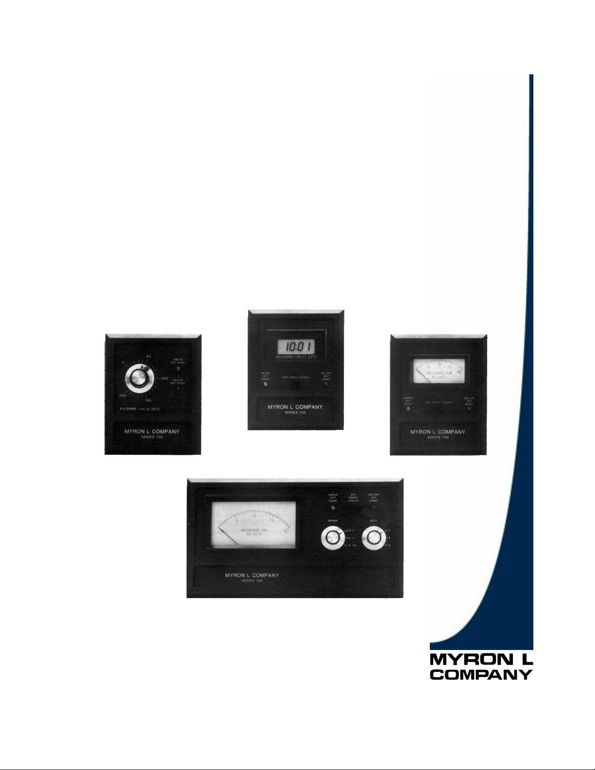
1.1.1 FUNCTIONAL DESCRIPTIONS
All models have drip/weather-proof housings suitable for panel,
bench or surface mounting. The 750 models are a compact 6.0"
(152mm) x 4.8" (122mm). The 767 model is 6.0" (152mm) x 10.8"
(275mm).
Bright green/red LEDs indicate below/above set point readings.
All models except 756 feature a heavy-duty 10 amp output relay,
operating on either increasing or decreasing readings.
For specific Monitor configurations, reference the following
individual model descriptions.
Model 755
Small controller only. Provides a front panel accessible set point
adjustment knob in place of an analog or digital meter readout
display.
Model 756
Small monitor only. Standard front panel is equipped with a linear
analog meter display only (no relay, LED indicators or set point
check switch).
Model 757
Small analog monitor/controller. Single set point is internal to
discourage unauthorized adjustments. Standard front panel is
equipped with a linear analog meter display and a “SET POINT
CHECK” switch.
Model 758
Small digital monitor/controller. Single set point is internal to
discourage unauthorized adjustments. Standard front panel is
equipped with a digital LCD meter display and a “SET POINT
CHECK” switch.
Model 767
Large analog monitor/controller. Single set point is internal to
discourage unauthorized adjustments. Standard front panel is
equipped with a three (3) range select switch, analog meter display
and a “SET POINT CHECK” switch. Options include three (3) cell
input capability and dual set point control.
1.1.2 APPLICATIONS
1 Reverse Osmosis
2 Process Control
3 Seawater Desalinization
4 Waste Treatment
5 Food Processing
6 Power Plants
7 Laboratories
1.2 SPECIFICATIONS
RANGES:
Refer to Conductivity/ppm Ranges sheet on Page 3 for
Conductivity Ranges.
READOUT:
Model 756: 2 1/2" (63mm) analog meter
Model 757: 2
Model 758:
1
/2" (63mm) analog meter
1
/2" (13mm) 3 1/2 digit LCD
Model 767: 4 1/2" (114mm) analog meter
ACCURACY:
Model 758: ± 1 % of span
Other Models: ± 2% of span
SENSITIVITY:
0.05% of span
STABILITY:
0.05% of span
REPEATABILITY:
0.1% of span
CALIBRATION CHECK:
Built in
RECORDER OUTPUT:
0-10 VDC @ 5mA max. (linear); standard on all models
CELL INPUT:
1 (optional 3 Cell Input available on Model 767)
RELAY FUNCTION:
Models 755, 757, 758 and 767:
Single set point control continuously adjustable 0-100% of
span
Indicators:
“ABOVE” (red) and “BELOW” (green) set point LEDs
Contact Rating:
SPDT 10 amp @ 250 VAC, 30 VDC. Relay operates
increasing or decreasing reading (selectable).
Optional on Model 767 only:
Dual set point control, with above specifications
POWER SPECIFICATIONS:
115 VAC ± 15%, 50/60 Hz, 25 mA
220 VAC (User changeable)
DIMENSIONS 750 SERIES:
6.0" (152mm) H x 4.8" (122mm) W x 3.8" (96mm) D
DIMENSIONS 760 SERIES:
6.0" (152mm) H x 10.8" (275mm) W x 3.9" (99mm) D
AMBIENT TEMPERATURE RANGE:
-22°F (- 30°C) to 140°F (60°C)
HOUSING CONSTRUCTION:
Fully gasketed heavy-duty ABS for corrosion resistance. Rated
NEMA type 3.
WEIGHT:
750 Series: 2 Ibs. (0.9 kg)
760 Series: 3 Ibs. (1.4 kg)
1
Page 4
1.3 CONDUCTIVITY CELLS
Both 750 and 760 series conductivity models use the CS51 or
CS52 Series cell. The 1.0 cell constant CS51 model is
recommended for ranges of 0-20 through 20,000µS. Its compact
size allows mounting in the top of a standard 3/4" tee. The
sturdy polypropylene bushing is modular for easy, inexpensive
replacement.
CS52 cells have a 10.0 constant and are used for conductivity
values above 20,000µS.
1.3.1 CELL SPECIFICATIONS
CONSTANT:
CS51LC: 0.1
CS51: 1.0
CS52: 10.0
TEMPERATURE COMPENSATION:
Automatic to 25°C, between 32-212°F (0-100°C)
PRESSURE/TEMPERATURE LIMITS:
100 psi (689.6 kPa) at 212°F (100°C)
BUSHING:
CS51 (LC): Modular Polypropylene threaded 3/4" NPT
CS52: 316 stainless steel 3/4" NPT internal to cell body
CABLE:
Shielded; 10' (3 meters) standard; 25' (7 meters) and 100'
(30 meters) lengths also available.
DIMENSIONS:
CS51 (LC): Metal portion 1.2" (30mm) L; 0.5" (13mm) DIA
CS52: Contact factory for specifications
1.4 OPTIONAL FEATURES
-03: 3 cell input (767 only)
-420: 4-20 mA isolated output (758 only)
-420D: 4-20 mA self powered isolated output (758, 767 only)
-DP: Dual set point (767 only)
-RM: Remote meter (767 only)
1.4.1 ACCESSORIES
MODEL TYPE
PC: 110V Power cord (8 foot with plug and strain relief
fitting)
SMP50: Surface mounting plate for 750 series
SMP60: Surface mounting plate for 760 series
60AM: 4 1/2" analog meter for 767-RM (specify range)
3CE: 3 cell switch with enclosure and trimplate
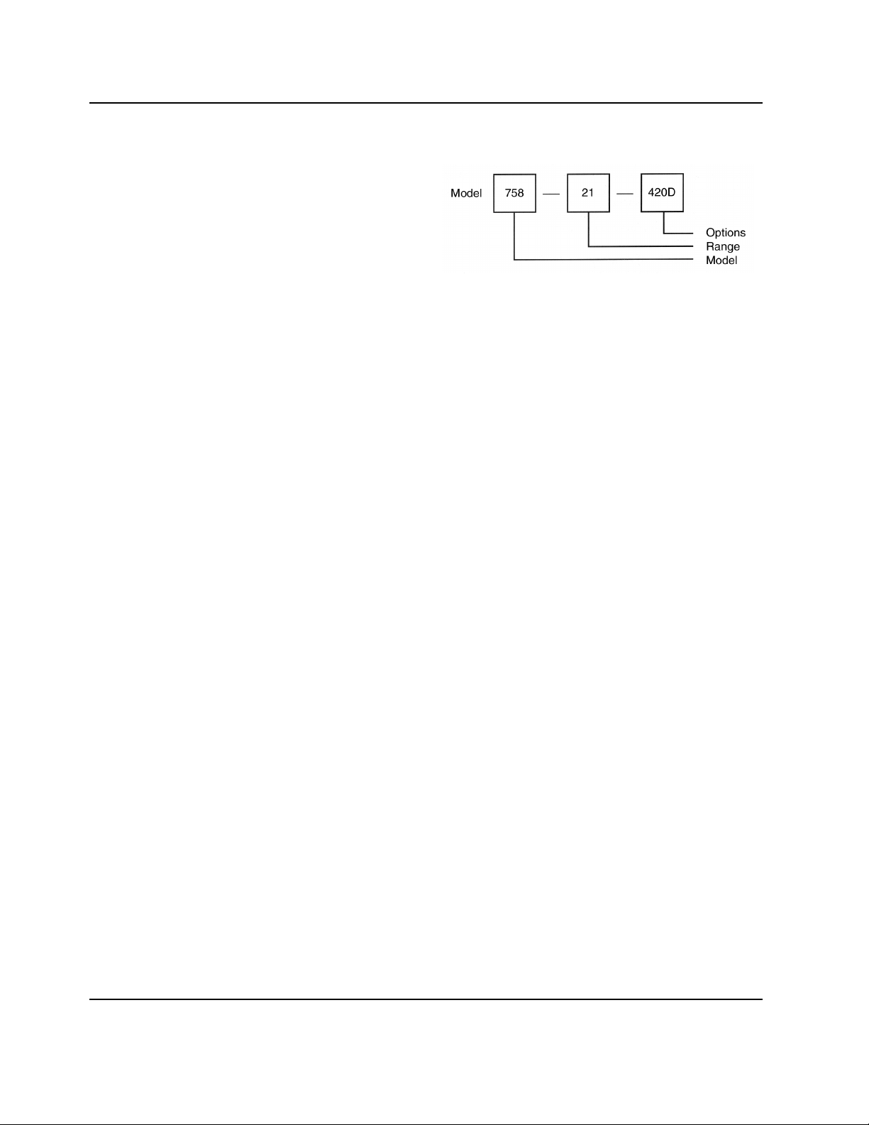
1.5 HOW TO ORDER MONITOR/CONTROLLERS
EXAMPLE:
This is a small digital monitor/controller with a 0-2000µS range
and 4-20mA output.
NOTE:
Monitor model number does not include cell. Please specify
cell required when ordering.
MODEL TYPES:
755: Small controller only
756: Small analog monitor only (no relay)
757: Small analog monitor/controller
758: Small digital monitor/controller
767: Large 3-range analog monitor/controller
RANGE SUFFIXES:
See CONDUCTIVITY/ppm RANGES sheet, Page 3.
1.5.1 HOW TO ORDER CELLS
CS51 LC: For 0-2µS range
CS51: For ranges 20 to 20,000µS or ppm
CS52: For ranges above 20,000µS or ppm see
CONDUCTIVITY/ppm RANGES sheet, Page 3.
CELL CABLE SUFFIX
-25: 25' (7 meters) shielded cell cable
-100: 100' (30 meters) shielded cell cable
2
Introduction
Page 5

Conductivity/ppm Ranges
CS51 SERIES CELLS SUITABLE FOR ALL EXCEPT THOSE NOTED
SUFFIX 755 756 757 758 767
TO CONTROL ANALOG ANALOG DIGITAL LG. ANALOG
RANGE MODEL NO. CONTROL CONTROL CONTROL
0-2 µS *** -6 X
0-20 µS-9 X X X X
0-20 ppm -10 X X X X
0-50 µS-11 X X X
0-50 ppm -12 X X X
0-100 µS -13 X X X X
0-100 ppm -14 X X X X
0-200 µS -15 X X X
0-200 ppm -16 X X X
0-500 µS -17 X X X X
0-500 ppm -18 X X X X
0-1000 µS -19 X X X X
0-1000 ppm -20 X X X X
0-2000 µS -21 X X X X
0-2000 ppm -22 X X X X
0-5000 µS -23 X X X**
0-5000 ppm -24 X X
0-10,000 µS -25 X X X**
0-10,000 ppm -26 X X
0-20,000 µS -27 X X use-29**
0-20,000 ppm -28 X X
0-20 mS -29 X
0-20, 200,
2,000 µS -30 X
0-20, 200,
2,000 ppm -31 X
0-50, 500,
5,000 µS -32 X
0-50, 500,
5,000 ppm -33 X
0-100, 1,000,
10,000 µS -34 X
0-100, 1,000,
10,000 ppm -35 X
0-200, 2,000,
20,000 µS -36 X
0-200, 2,000,
20,000 ppm -37 X
0-500, 5,000,
*50,000 µS -38 X
0-500, 5,000,
*50,000 ppm -39 X
*0-50,000 µS -40 X X
*0-50,000 ppm -41 X X
*0-100,000 µS -42 X X
*0-200,000 µS -44 X X
*0-200 mS -46 X
INSTRUMENT ONLY MONITOR MONITOR/ MONITOR/ MONITOR/
*CS52 SERIES CONDUCTIVITY CELLS REQUIRED FOR THESES RANGES
** READS IN MILLISIEMENS (mS)
*** CS51LC CELL (0.1 constant) REQUIRED FOR THIS RANGE
NOTE: UNLESS ppm/NaCl is specified with order, ppm type conductivity instruments will be calibrated on the
Myron L “442” Natural Water™ standard
3
Page 6

SECTION 2
Installation
2.1 GENERAL
This section provides the recommended procedures for properly
installing the 750/760 Series Conductivity Monitors and cells.
WARNING!
The Myron L Company recommends that all mounting and
electrical installation procedures be performed by trained and
authorized personnel ONLY! Failure to do so could result in
personal injury or loss of life. In addition, damage to the
equipment and/or property may occur.
2.2 MECHANICAL INSTALLATION
All Monitor electronics are packaged inside drip/weather-proof
housings. The physical dimensions of both small and large
housings are suitable for panel, bench or surface mounting.
There are three basic guidelines to consider when selecting a
Monitor’s mounting location:
STEP 1 Select a site that limits the Monitor’s exposure to
excessive moisture and corrosive fumes.
STEP 2 For best results, position your control area as close as
possible to the point(s) being controlled.
4
Page 7

NOTE:
The 750/760 Series Conductivity Monitors are not designed to
operate with a Cell cable length that exceeds 100' (30 meters).
STEP 3 If at all possible, mount the Monitor at eye level for
viewing convenience.
2.2.1 SURFACE MOUNTING WITH SMP ASSEMBLY
NOTE:
A Surface Mounting Plate (SMP) will be required when access to
the far side of the mounting site is impractical. For 750 series
monitors, use the SMP-50 and for 760 series monitors, use the
SMP-60. Surface mounting will require two (2) 1/4" X 20
mounting screws. (The mounting screws are packaged with the
SMP assemblies.) If an SMP is being used, the user must
supply four (4) additional screws or bolts. Their size is to be
determined by the user.
STEP 1 Select your mounting location. Mark and drill the four
(4) required mounting holes. For hole locations, use the
SMP as a template. Install any lags or threads required.
STEP 2 Drill the corner holes in the SMP according to the size
of the screws or bolts selected.
STEP 3 Attach and securely fasten the SMP to the Monitor
using the 1/4" X 20 X 3/8" screws provided.
STEP 4 Mount the SMP to the prepared site using the selected
screws or bolts.
2.2.2 SURFACE MOUNTING WITHOUT SMP ASSEMBLY
NOTE:
Surface mounting will require two (2) 1/4 “ X 20 screws of a
length equal to the thickness of the mounting site plus 3/8”
STEP 1 Select mounting site location. Mark and drill the
required mounting holes. For hole drilling locations, see
Fig. 2-1.
STEP 2 Insert the 1/4" X 20 screws into the holes from the side
opposite the mounting site.
STEP 3 Hold the Monitor in place while starting and tightening
the mounting screws.
2.2.3 PANEL MOUNTING
A panel mounting fastening kit is provided with all Conductivity
Monitors. Panel mounting will require the use of the fastening
kit’s two (2) 4-40 mounting screws/nuts or two (2) #4 x 1/2"
sheet metal screws. See Fig. 2-1 for panel cutout dimensions.
STEP 1 Select your mounting location. Mark the appropriate
panel cutout and complete the necessary panel cut.
STEP 2 Carefully unfasten and separate the Monitor’s front
panel from its enclosure.
STEP 3 Disconnect all panel cable(s)/wires from the Monitor’s
Control board.
STEP 4 Slide the enclosure through the panel cutout until its
flange contacts the panel.
STEP 5 Insert mounting screws through the flange mounting
holes and tightly secure.
STEP 6 Reconnect all panel cable(s)/wires and re-secure the
front panel.
2.3 CELL INSERTION/DIP MOUNT ASSEMBLIES
A CS51 Cell’s mounting orientation must provide a continuous
and adequate circulation flow to prevent the trapping of air
bubbles within the Cell’s electrode area. Failure to do so will
result in conditions that will prevent the Cell from functioning
properly.
2.3.1 INSERTION MODE ASSEMBLY
STEP 1 Verify that the Cell’s Fitting assembly is properly
assembled as shown in Fig. 2-2.
STEP 2 Insert the Cell Fitting assembly into the “T” fitting as
shown in Fig 2-2 and tightly secure.
2.3.2 ALTERNATE DIP CELL ASSEMBLY
STEP 1 Verify that the Cell’s Fitting assembly is properly
assembled as shown in Fig. 2-3.
STEP 2 Insert and pull the Cell’s cable through the extension
tube and then tightly attach extension tube to Cell
assembly as shown in Fig. 2-3.
Installation
5
Page 8

2.4 ELECTRICAL INSTALLATION
The electrical installation procedures provided in this manual are
common to all Conductivity Monitors. See Fig. 2-1 for the hole
dimensions of the enclosure’s cable access holes. Unless
otherwise instructed, refer to Fig. 2-4 and 2-5 for the 750/760
Series Monitor’s terminal block (TB) connector wiring
designations.
NOTE:
After removing an enclosure’s access hole plug, it is suggested
that the user mount a watertight restraint fixture prior to installing
a cable.
2.4.1 MAIN AC POWER INSTALLATION
The following procedures are to be used to install a standard
115 VAC main power source. For the procedures to install the
optional 220 VAC main power source, the user must first
complete the conversion procedures in Section 2.4.2.
STEP 1 Verify that the facility’s main AC power source is turned
STEP 2 Carefully remove front panel, leaving the cable and
STEP 3 Place the facility’s AC power cord and user supplied
STEP 4 Neatly connect cable wires to the Monitor’s TB
“OFF” or disconnected.
wires connected.
watertight cable restraint into the enclosure’s
appropriate access hole.
connectors, as shown in Fig. 2-4 and 2-5.
6
Installation
Page 9

2.4.2 220 VAC CONVERSION
STEP 1 Verify that the facility’s main AC power source is turned
“OFF” or disconnected.
STEP 2 Locate and remove the Control board jumpers E1 and
E3. (See Fig. 2-6.)
STEP 3 Using one of the removed jumpers, insert it into jumper
E2’s connection holes as shown in Fig. 2-6.
2.4.3 CONNECTING THE CELL CABLE
STEP 1 Place the Cell’s interface cable and user supplied
watertight cable restraint into the enclosure’s
appropriate access hole.
STEP 2 Neatly connect the Cell’s cable wires to the Monitor’s
appropriate TB connectors. (See Fig. 2-4 or 2-5.)
2.4.4 ALARM RELAY INSTALLATION
STEP 1 Place the user supplied Alarm relay interface cable and
watertight cable restraint into the enclosure’s
appropriate access hole.
STEP 2 Neatly connect the Relay cable wires to the Monitor’s
TB connectors (See Fig 2-4-1 or 2-5-1) as explained
below. All Myron L Company Conductivity Monitor/
Controllers (except Model 756) are equipped with a
relay which is designed to energize/de-energize when
the set point is crossed. (See P.10, sec 3.3.2 for set
point adjustment procedure) The relay energizes on
increasing readings. The easiest method of connecting
the relay is shown below in FlGs 2-4-1 and 2-5-1.
These show how the dry contact relay can use
incoming power to activate a controlled device (alarm,
solenoid valve, etc.) of 10 amps or less. A usersupplied transformer is necessary if the controlled
device operates on a voltage different from the voltage
which powers your Myron L monitor/controller. An
alternative (necessary if the device is DC powered) is
to connect a separate, second power source to the
relay.
When energized (above set point), the Common (COM) will
disconnect from the Normally Closed NC contact and connect to
the Normally Open (NO) contact. Devices may be operated
using either the Normally Open contact or Normally Closed
contact; or both relay contacts may be used to activate two
devices of the same voltage.
2.5 0-10 VDC RECORDER OUTPUT
STEP 1 Place the user supplied interface cable and watertight
cable restraint into the enclosure’s appropriate access
hole.
STEP 2 Connect the Recorder’s plus (+) and minus (-) terminal
wires to the Recorder output’s TB connectors. (See Fig.
2-4 or 2-5)
STEP 3 Refer to Section 4.3.2 for the procedures to calibrate
the 0-10 VDC voltage output
2.6 CONNECTING THE MODEL 758 4-20mA AND 420D
OPTIONS
STEP 1 Place the user supplied cable and watertight cable
restraint into the enclosure’s appropriate access hole.
STEP 2 Neatly insert cable wires into the 758 Panel board’s
plus (+) and minus (-) TB1 terminal block connectors as
shown in Fig. 2-7.
STEP 3 See Section 4.3.3 to calibrate the 4-20mA minimum
and maximum current outputs.
2.7 INSTALLATION OF THE MODEL 767 OPTIONS
The Model 767 Conductivity Monitor/Controller can be
configured with a combination of options. Based upon user
requirements, the electrical installation of one or more of the
following options may be required.
2.7.1 CONNECTING THE 767-420D OPTIONS
STEP 1 Place the user supplied cable and watertight cable
restraint into the enclosure’s appropriate access hole.
STEP 2 Neatly connect the cable wires to the Monitor’s plus (+)
and minus (-) terminals TB1-4 & 5. (See Fig. 2-5.)
STEP 3 Refer to Section 4.3.5 for the procedures to calibrate
the Model 767’s 4-20mA minimum and maximum
current outputs.
NOTE:
The maximum impedance of the user’s current sensor should
not exceed 400 ohms.
2.7.2 CONNECTING THE REMOTE METER OPTION
STEP 1 Connect the Remote Meter cable and user supplied
restraint into the enclosure’s appropriate access hole.
STEP 2 Neatly connect the Remote Meter’s positive (+) and
minus (-) wires to terminals TB1-13 &14. (See Fig. 2-5.)
STEP 3 Refer to Section 4.3 for the procedures to calibrate the
Model 767’s Remote Meter output.
Installation
7
Page 10

SECTION 3
Operating Procedures
3.1 SWITCH AND INDICATOR CONTROLS
The front panel illustrations, switch and indicator operational
descriptions have been provided to assist the user in identifying
and operating the 750/760 Series Conductivity Monitors.
Refer to Section 3.3 for a Monitor’s Setup procedures and
Section 3.4 for Check-Out procedures.
3.1.1 RED “ABOVE SET POINT” LED INDICATOR
Standard on all models except the 756 small Monitor.
The red LED indicator light is ON only when the water’s
conductivity reading is ABOVE the Monitor’s set point
adjustment.
3.1.2 GREEN “BELOW SET POINT” LED INDICATOR
Standard on all models except the 756 small Monitor.
The green LED indicator light is ON only when the water’s
conductivity reading is BELOW the Monitor’s set point
adjustment.
3.1.3 SET POINT ADJUSTMENT KNOB
Available on the 755 controller only.
Front panel adjustment knob provides immediate access for
adjusting the Monitor’s set point setting and to verify its full scale
reading.
3.1 A “SET POINT CHECK” SWITCH
Available on the 757, 758 and 767 Monitor/Controllers only.
When the “SET POINT CHECK” switch is depressed, the
internal set point reading is immediately displayed on the front
panel display.
3.1.5 ANALOG/DIGITAL METER READOUTS
Models 756, 757 and 767 equipped with analog meters only.
Model 758 equipped with 1/2” digital meter only.
Front panel analog or digital meters provide a continuous
readout of the water being monitored.
3.1.6 3 “RANGE” SELECT SWITCH 767
Monitor/Controller only.
The “RANGE” select switch provides three (3) decades of
indication corresponding to 1, 10, or 100 times the meter
reading.
3.1.7 3 “CELL” INPUT SELECT SWITCH
Available as an optional feature on the 767 Monitor/Controller
only.
“CELL” input switch selects one (1) of three (3) Cells as the
active monitoring Cell input.
8
Page 11

3.2 MODEL 767 STANDARD AND OPTIONAL FEATURES
This section describes the standard and optional features of the
Model 767 Conductivity Monitor/Controller. (Refer to Fig. 3-1.)
Power Supply
The standard Monitor/Controller has a single power supply that
provides voltages for all circuit functions. It may be configured
for either a 110 VAC or a 220 VAC supply.
Conductivity
The conductivity circuit is designed as a three range device with
extremely accurate tracking between ranges. It receives raw
conductivity and temperature information from the Cell and
translates this into a voltage that may range from 0 to + 10 VDC.
This is the Recorder output. The Recorder output signal
represents the conductivity of the fluid at 25°C. This signal is
available at terminals TB1-6 & 7
Meter Drive Section
The 0-10 V signal is also taken to the display section where it is
used to drive the analog meter.
Alarm Section and Relay
The alarm circuit compares the signal from the conductivity
circuit with a “set point” signal controlled by the user. The user
may check the current set point by pressing the “SET POINT
CHECK” switch on the front panel. This feeds the set point
signal to the Meter Drive section, which then displays the set
point on the meter.
Normally, if the conductivity signal becomes greater than the set
point signal, the alarm relay will be energized. The user may
adjust two jumpers that will cause the alarm relay to be
energized when the conductivity signal is less than the set point
signal.
Options:
03: the “03” option replaces the single Cell with three
separate Cells and a switch that allows you to switch
between each Cell.
420D: The “420D” option replaces the standard 0-10 V Recorder
output with a completely isolated 0-10 V output. In
addition, a 4-20 mA current loop output is available at
terminals TB1-4 & 5. These circuits have their own
completely separate power supply.
DP: The “DP” option adds a second alarm circuit (Alarm B),
which is identical to the first.
RM: The “RM” option adds circuitry to drive a remote 1 mA
analog meter movement.
3.3 SETUP PROCEDURES
These Setup procedures cover (1) setting the alarm circuit set
point(s), and (2) converting the alarm circuit to trigger on a
decreasing reading.
Operating Procedures
9
Page 12

3.3.1 DECREASING SET POINT CONVERSION
The alarm circuit(s) on all 750/760 Series Conductivity Monitors
are configured to trigger the alarm relay as the conductivity (or
ppm) reading increases. If the user’s application requires it, the
alarm circuit may be easily reconfigured to trigger the alarm
relay as the conductivity (or ppm) reading decreases. Refer to
Fig. 4-1 for the locations of the jumpers referred to in this
section.
NOTE:
These instructions describe the general procedures for
converting the Monitor without reference to jumper numbers or
orientation. Refer to Fig. 3-2 or 3-3 for the specifics on your
Monitor.
STEP 1 Turn OFF or disconnect the Monitor’s main AC power.
STEP 2 Locate the jumper block for the alarm to be configured.
STEP 3 Make a note of the current orientation of the jumpers.
STEP 4 Remove both jumpers. This is easily done by hand.
Take care not to crush the jumpers if using pliers.
STEP 5 Rotate the jumpers,/turn and reinstall them on their
posts.
3.3.2 SET POINT ADJUSTMENT
NOTE:
Because the Model 755 is equipped with a standard front panel
Set Point trimmer adjustment knob, it does not have an internal
set point adjustment setting. Refer to Section 3.4.1 for
procedures to adjust the 755’s set point.
STEP 1 Being careful not to strain the cable, unfasten and
remove the Monitor’s front panel.
STEP 2 While depressing the “SET POINT CHECK” switch,
turn the Monitor’s Set Point trimmer adjustment screw
(See Fig. 4-1) until the desired set point value is
indicated on the meter display.
NOTE:
The Monitor’s set point setting is based upon the user’s
particular water purity specifications.
STEP 3 After successfully completing STEP 2, remount the
front panel and tightly secure both retaining screws.
3A CHECK-OUT PROCEDURES
The following check-out procedures are used to verify that a
750/760 Series Conductivity Monitor is operating properly. It is
assumed that the Monitor is powered ON, that it is connected to
a CS51 or CS52 Cell, and that the Cell is immersed in water
within the range that the Monitor will be required to read. Refer
to Fig. 4-1 for the locations of the components referred to in this
section.
3.4.1 MODEL 755 (Only)
STEP 1 Turn the front panel adjustment knob to its full scale
setting. The green “BELOW SET POINT” light should
be ON indicating that the water being monitored is
BELOW the controller’s monitoring set point.
STEP 2 Turn the front panel adjustment knob to its zero scale
setting. The red “ABOVE SET POINT” light should be
ON indicating that the water being monitored is ABOVE
the controller’s monitoring set point.
STEP 3 Turn the adjustment knob back and forth and note the
reading where the ABOVE and BELOW LED indicator
lights switch. Also note an audible click as the relay
picks up and drops out. This reading corresponds to
the actual water purity.
STEP 4 Reset the Set Point trimmer adjustment knob to the
desired set point.
3.4.2 MODELS 756, 757, 758, & 767
NOTE:
A small screwdriver will be required.
STEP 1 Make a note of the reading on the Monitor’s display.
STEP 2 Being careful not to strain the connecting cable(s),
unfasten and remove the Monitor’s front panel.
STEP 3 (For the Model 767 only!) Place the “RANGE” select
switch to its “X1” setting.
STEP 4 While holding the Calibration Test switch (SW1) to its
TEST position, verify that the front panel meter is
indicating a full scale reading.
STEP 5 Press and hold the “SET POINT CHECK” switch on the
front panel. Using the small screwdriver, adjust the Set
Point trimmer adjustment screw on the circuit board to
sweep the display from zero to full scale. (A digital
display may be blank at the full scale end. This is
normal.) Listen for the alarm relay to click on and off as
the alarm set point moves past the water reading.
STEP 6 Adjust the alarm to the desired set point. Release the
“SET POINT CHECK” switch.
NOTE:
For Model 767-DP, repeat STEPS 5 & 6 to check out Alarm B.
10
Operating Procedures
Page 13

SECTION 4
Component Identification/Calibration and Preventive Maintenance
4.1 PRIMARY COMPONENT IDENTIFICATION
As identified in Section 3, the Conductivity Monitors’ switch and
indicator components are mounted directly to the front panel.
The Conductivity Monitors’ Control boards are contained within
and mounted to the back of the enclosure. The 767 Monitor,
when equipped with the 3 Cell Input option, has a second
component board mounted on the back of the front panel.
Model 758-420 and 758-420D have an additional board
mounted behind the front panel.
11
Page 14

4.2 METER MECHANICAL ZERO PROCEDURES
Models 756, 757 & 767 (Analog Meters Only)
STEP 1 Turn OFF or disconnect the Monitor’s main AC power.
STEP 2 Note the position of the meter needle. If it has come to rest
pointing at the zero mark on the scale, turn the Monitor back
ON and continue on the Section 4.3.
STEP 3 Locate the small (approx.
1
/4”), black plastic button directly
below the center of the meter. Use a small screwdriver or a
fingernail to gently pry it loose and remove it from the access
hole.
STEP 4 Insert a small standard screwdriver into the access hole and
carefully locate the slot in the mechanical adjustment plug.
STEP 5 Turn the adjustment plug slightly until the needle rests on
zero.
STEP 6 Insert the small plastic button into the access hole.
STEP 7 Turn ON or reconnect the Monitor’s main AC power.
4.3 CALIBRATION PROCEDURES
All Myron L Conductivity Monitors/Controllers are factory calibrated
prior to shipping and are ready to install without further calibration.
Calibration should be checked occasionally with the internal
Calibration Test switch (SW1) to ensure continued accuracy. The
following procedures are provided in the event that re-calibration
becomes necessary. The only equipment required are a small
screwdriver, standard solution, and an accurate multimeter. Calibration
should be accomplished by a qualified technician.
Refer to Fig. 4-1 to locate the components described in this section.
CAUTION!
When performing calibration procedures, the technician must take
extreme care to avoid contacting the fuse or control circuitry other than
trimmer calibration screws. Failure to do so could result in damage to
the equipment and/or property.
4.3.1 CALIBRATION PROCEDURES USING STANDARD SOLUTION
The best method of recalibrating your conductivity monitor/controller is
with NIST traceable Standard Solution (available from your Myron L
Company distributor, or elsewhere). Because it includes the sensor,
the entire instrument is recalibrated.
Step 1 Obtain a standard solution which is 60-90% of full scale of
the instrument.
Step 2 Adjust the temperature of the standard solution to 25°C. This
may be accomplished by using a warm or cool bath for the
bottle.
Step 3 Obtain a clean glass beaker. Rinse beaker thoroughly with
the standard solution. Place cell (sensor) of instrument in the
beaker of standard solution. Level of standard solution
should be high enough to cover
1
/2" above bore hole. Slowly
shake the sensor to remove air bubbles from inside the
sensor bore hole.
Step 4 Allow 3-4 minutes for temperature to equilibrate. Read the
display of the instrument. The display should match the
value and units of measure located on the bottle of standard
solution. If the reading is different, adjust R25 on the main
circuit board until the reading matches the solution value.
This will require removal of the front cover. NOTE: Remove
front cover with care; a ribbon cable connects the front
panel and main board.
4.3.2 CALIBRATION PROCEDURES (CIRCUIT ONLY)
This method is faster than the method using standard solution, but it
does not include the sensor. Therefore, it should be used only in
applications where the chance of sensor contamination or damage are
slight.
4.3.2.1 MODEL 755
STEP 1 Connect a voltmeter (0-10 VDC) to the Recorder output
terminals TB2-6 & 7 with the positive (+) lead on TB2-7.
STEP 2 Press and hold the Calibration Test switch (SW1). The
voltmeter should indicate +10 volts. If not, set to +10 volts
with the Main Calibration trimmer (R9).
STEP 3 Set the front panel control knob to the full scale setting. With
the Calibration Test switch (SW1) still depressed, rotate the
front panel control knob above and below the full scale
setting several times to locate the setting at which the front
panel LEDs switch. You should find one upper setting where
the LEDs switch from red to green and one lower setting
where they switch from green to red. The full scale index
mark should be halfway between these two settings. If
necessary, loosen the control knob set screws and reposition
the knob. This completes the calibration.
4.3.2.2 MODELS 756, 757 & 758
STEP 1 Connect a voltmeter (0-10 VDC) to the Recorder output
terminals TB2-6 & 7 with the positive (+) lead on TB2-7.
STEP 2 Press and hold the Calibration Test switch (SW1). The
voltmeter should indicate +10 volts. If not, set to +10 volts
with the Main Calibration trimmer (R9).
STEP 3 With the Calibration Test switch (SW1 ) still depressed, set
the Front Panel Meter trimmer (R25) for a full scale
indication on the panel meter. If you have a digital readout
(model 758), set it to 1999 (decimal point omitted) for ranges
0-20, 200 or 2000. For all other ranges, set it to read the
range maximum. If not known, this can be determined by
looking up the range suffix on the enclosure’s model label in
the list on page 3 of this manual.
Example: For model 758-11 (0-50 µS), set front panel LCD to indicated
50.0 µS.
4.3.3 MODEL 758 WITH 4-20 mA OR 4-20D OPTION
NOTE: FOR 4-20D, PROCEED TO STEP 1.
CAUTION! FOR 4-20mA OPTION ONLY
The proper supply voltage (V Supply) and load resistance (R) must be
selected. Failure to do so could result in damage to the 758 optional
panel board.
NOTE:
The proper load resistance (in ohms) is found by using the formula
and/or chart as shown in Fig. 4-2.
STEP 1 Set the controls of a test meter to read at least 20mA and
connect it between the positive terminals of the Transmitter
and Receiver as shown in Fig. 4-3 (4-20 mA option) and Fig.
4-4 (4-20D option).
STEP 2 Press and hold the “SET POINT CHECK” switch. It must be
depressed during all the following adjustment steps.
STEP 3 Turn the Set Point trimmer (R28) until the meter displays a
reading 0.00.
STEP 4 Turn the 4-20 mA Null trimmer (R23) (see Fig. 4-1 ) until the
test meter indicates 4 mA.
STEP 5 Readjust the Set Point trimmer (R28) until the meter displays
1999 (decimal point omitted).
STEP 6 Turn the 4-20 mA Full Scale trimmer (R20) (See Fig. 4-1 )
until the test meter indicates 20 mA.
STEP 7 Repeat STEP 3 through STEP 6, readjusting as required.
STEP 8 Reset the set point to the desired setting. Release the “SET
POINT CHECK” switch.
12
Component Identification/Calibration and Preventive Maintenance
Page 15

4.3.4 MODEL 767
NOTE:
The following procedures are for the standard Model 767 Refer
to Section 4.3.5 for the procedures to calibrate a Model 767
which is equipped with the 420D self-powered isolated output
option.
STEP 1 Set the “RANGE” select switch to its “X1” position.
STEP 2 Connect an accurate DC voltmeter to the Recorder
output terminals TB1-6 & 7 with the positive (+) lead on
TB1 -6.
STEP 3 While holding the Calibration Test switch to its TEST
position, set the Main Calibration trimmer to indicate a
+10 volt reading on the test meter.
STEP 4 While holding the Calibration Test switch to its TEST
position, set the Front Panel Meter trimmer (R25) to
indicate a full scale reading on the front panel meter. If
the Monitor/Controller is equipped with the Remote
Meter option, adjust the Remote Meter trimmer (R28) in
the same manner.
4.3.5 MODEL 767 EQUIPPED WITH THE 420D OPTION
For this calibration procedure, the Monitor/Controller must be
connected to a conductivity sensor with the white and black
wires disconnected. If a sensor is not available, it can be
simulated with a 10,000 ohm resistor connected between
terminals TB1-10 and TB1-11.
STEP 1 Set the “RANGE” select switch to its “X1” setting.
STEP 2 While holding the Calibration Test switch (SW1) to its
TEST position, set the Main Calibration trimmer (R6) to
indicate a full scale setting on the front panel meter.
STEP 3 Connect an accurate DC voltmeter to the Recorder
Output terminals TB1-6 & 7 with the positive (+) lead on
TB1-6.
STEP 4 While holding the Calibration Test switch (SW1) to its
TEST position, set the Isolated Output trimmer (R57) to
indicate a +10 volt reading on the test meter.
STEP 5 Connect an accurate DC milliammeter to the 4-20 mA
output terminals TB1-4 & 5 with the positive (+) lead on
TB1-4.
STEP 6 Leaving the Calibration Test switch (SW1) at its
OPERATE position, set the 4-20 mA Null trimmer (R63)
to indicate 4 mA on the test meter.
STEP 7 While holding the Calibration Test switch (SW1) to its
TEST position, set the 4-20 mA Full Scale trimmer
(R60) to indicate 20 mA on the test meter.
STEP 8 If your Model 767 is equipped with the Remote Meter
option (RM), hold the Calibration Test switch (SW1) to
its TEST position and set the Remote Meter trimmer
(R28) to indicate a full scale reading on the remote
meter.
4.4 PREVENTIVE CARE
The Myron L Company recommends that the following
Preventive Care procedures be observed.
STEP 1 Try to prevent exposure to excessive heat and
moisture.
STEP 2 The Monitor’s main AC power source must be
protected against excessive voltage “spikes.”
STEP 3 Take care not to damage the Monitor during handling.
NOTE:
Daily, weekly or monthly maintenance schedules are based
upon the frequency of use and the severity of the Monitor’s
environment and operating conditions.
STEP 4 Repeat the Monitor’s Check-Out procedures to verify
satisfactory operation and/or isolate possible
troubleshooting symptoms.
STEP 5 Check all cable connections to ensure that they are
free of moisture and contamination.
STEP 6 Inspect and replace damaged component boards and
cable assemblies.
STEP 7 Periodically remove and clean and inspect the
conductivity Cell.
Component Identification/Calibration and Preventive Maintenance
13
Page 16

WARRANTY
All Myron L monitors and cells have a one-year warranty. If any monitor or cell fails to function normally,
return the faulty unit to the factory prepaid. If, in the opinion of the factory, failure was due to materials or
workmanship, repair or replacement will be made without charge. A reasonable service charge will be made
for diagnosis or repairs due to normal wear, abuse or tampering. Warranty is limited to the repair or
replacement of monitor or cell only. The Myron L Company assumes no other responsibility or liability.
SECTION 5 REPLACEABLE
Appendix COMPONENTS CHART
DESCRIPTION MLC PART NO.)
755 Control Board 55RM*
755 Panel Cable Assembly 55RCA
756 Control Board 56RM*
756 Panel Cable Assembly 56RCA
1
/2" Analog Meter 50AM*
756 2
757 Control Board 57RM*
757 Panel Cable Assembly 57RCA
757 2 1/2" Analog Meter 50AM*
758 Control Board 58RM*
758 Panel Digital Assembly 58RCA
758 Digital Panel Meter 58DPM*
758 Digital Panel Meter with -420 Option 420MO1*
758 Digital Panel Meter with -420D Option 420DMO1*
750 Series Enclosure 50EC
750 Series Front Panel w/Lbl., Gasket and Screws 50FP
767 Control Board 67RM*
767 Control Board with -420D Option 674RM*
767 Control Board with -DP Option 67DPRM*
767 Control Board with -RM Option 67MRM*
767 Control Board with -420D-DP Options 674DPRM*
767 Control Board with -420D-RM Options 674MRM*
767 Control Board with -DP-RM Options 67DPMRM*
767 Control Board with -420D-DP-RM Options 674DPMRM*
767 Panel Cable Assembly 67RCA
767 Panel Cable Assembly for -DP Option Model 67DPRCA
767 3 Cell (-03) Option Board w/Cable Assembly 6703RCA
767 3 Cell (-03) Board for -DP Models w/Cable Assembly 6703DPRCA
1
767 4
/2" Analog Meter 60AM*
760 Series Enclosure w/Gasket 60EC
760 Series Front Panel w/Labels and Screws 60FP
Control Board Fuse
1
/8 AMP AGC 1/8 (all models) FUSE
WHEN ORDERING ANY PART, COMPLETE MODEL NUMBER MUST BE SPECIFIED.
* WHEN ORDERING THESE PARTS, RANGE SHOULD ALSO BE SPECIFIED.
pH Conductivity Instrumentation
Accuracy • Reliability • Simplicity
6115 Corte del Cedro
Carlsbad, CA 92009-1516 USA
Tel 760-438-2021
Fax 800-869-7668 / 760-931-9189
www.myronl.com
 Loading...