

Myricom Myrinet/PCI-X Network Interface Cards Installation Manual
Guide to Myrinet/PCI-X Network Interface
Cards
Hardware & Software Installation
Principles of Operation
Myricom, Inc
.
Date: 11 March 2005
The most recent version of this document can be downloaded from
http://www.myri.com/scs/doc/guide_to_pcix_nics.pdf
© 2005 Myricom, Inc. DRAFT
1

Regulatory Information
Electromagnetic Compatibility (EMC)
Myrinet-Fiber (M3F) network interface cards (NICs) and their fiber cables are fully
compliant with the following standards and specifications for the emission of and
susceptibility to electromagnetic interference (EMI):
European Union
® BS EN55024 (1998)
® BS EN61000-3-2 (2001)
® BS EN61000-3-3 (1995) W/A1:98
® BS EN55022 (1998) Class A
United States
FCC Part 15 Subpart B Class A using:
® FCC Part 15 Subpart B Section
15.109 Class A
® CISPR 22 (1997) Class A
® ANSI C63.4 (1992) method
On the basis of these EMC certifications and other engineering data, these products carry
the CE mark. A copy of the current Declaration of Conformity can be found linked from
the product specifications on the web at www.myri.com.
Laser Device Safety
The optical-fiber transceivers used in the M3F family of products are Class I Laser
Products. Optical-fiber components with this classification pose no threat of biological
damage, and are considered to be safe.
Disposal of Components that Contain Lead
Myrinet NICs contain small quantities of lead in the tin-lead solder. Please dispose of
them safely. Disposal of lead-containing electronic components through regular trash
channels is prohibited in many countries and regions, because the lead leached out of
landfills may contaminate groundwater supplies. Myricom has proper channels for the
disposal of these materials, and will dispose of any Myrinet products returned for that
purpose to Myricom.
Australia/New Zealand
AS/NZS 3548 (1005 W/A1 & A2: 97)
Class A using:
® BS EN55022 (1998) Class A
Canada
ICES-003 Class A using:
® CISPR 22 (1997) Class A
® ANSI C63.4 (1992) method
Japan
VCCI (April 2000) Class A using:
® CISPR 22 (1997) Class A
© 2005 Myricom, Inc. DRAFT
2
Introduction
Myricom currently produces three series of Myrinet/PCI-X Network Interface Cards
(NICs): the PCIXD series with 225MHz RISC and memory, and the PCIXE series and
PCIXF series with 333MHz RISC and memory. These series of NICs have the “low
profile PCI Short Card” form factor. The product codes follow this scheme:
Physical Port Form factor NIC type Memory
M3F- (Myrinet-Fiber) PCIX D -2, -4
M3F2- (Myrinet-Fiber) PCIX E -2, -4
M3F- (Myrinet-Fiber) PCIX F -2, -4
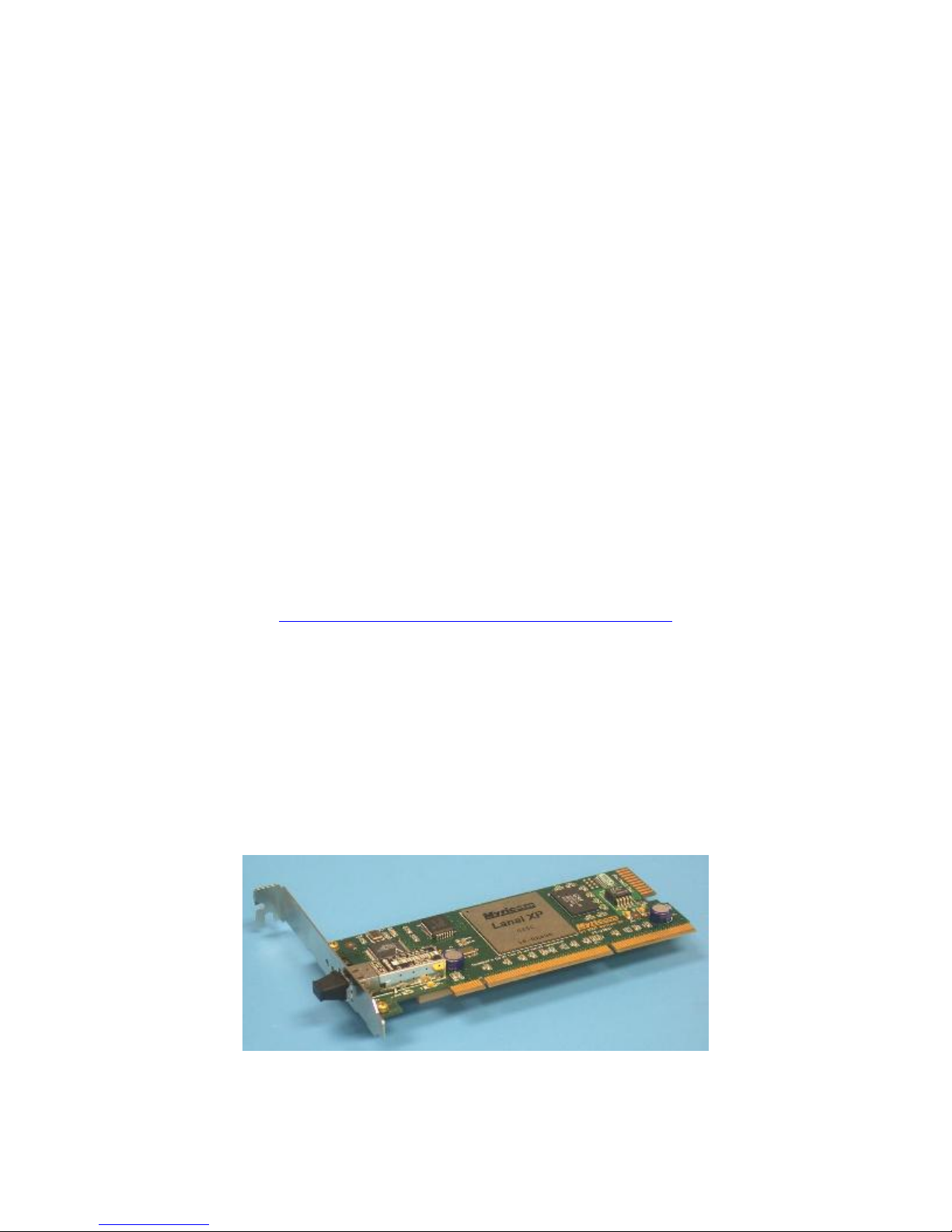
such that, for example, a M3F-PCIXD-2 NIC has one Myrinet-Fiber port, has the
Myricom Lanai XP processor operating at 225MHz, and has 2MB of local memory. A
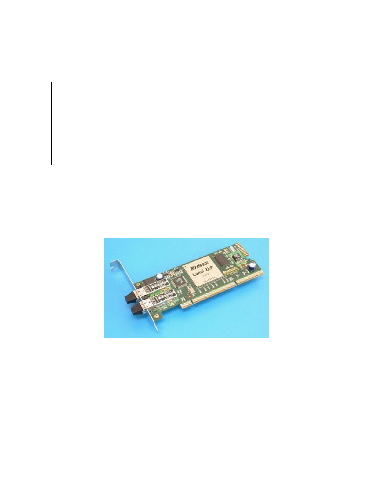
M3F2-PCIXE-2 NIC has two Myrinet-Fiber ports, has the Myrinet Lanai 2XP processor
operating at 333MHz, and has 2MB of local memory. A M3F-PCIXF-2 NIC has one
Myrinet-Fiber port, has the Myricom Lanai 2XP processor operating at 333MHz, and has
2MB of local memory. Not all combinations are produced. The NICs that are in current
production are listed at:
http://www.myri.com/myrinet/full_product_list.html
This listing also includes prices and links to the detailed product specifications.
The low profile PCI short cards, as pictured below, are available with Myrinet ports for
Myrinet-Fiber (LC-connectorized 50/125 multimode fiber cables). (Note that PCIXD
NICs shipped between May 2003 and February 2005 are based on the Lanai-XP chip and
its memory operating at 225MHz. Later production of PCIXD NICs is based on a Lanai2XP chip and its memory operating at 225MHz. The two versions of PCIXD NICs are
form+fit+function equivalent.)
M3F-PCIXD-2 Myrinet-Fiber / PCI-X NIC with a standard PCI faceplate
© 2005 Myricom, Inc. DRAFT
3
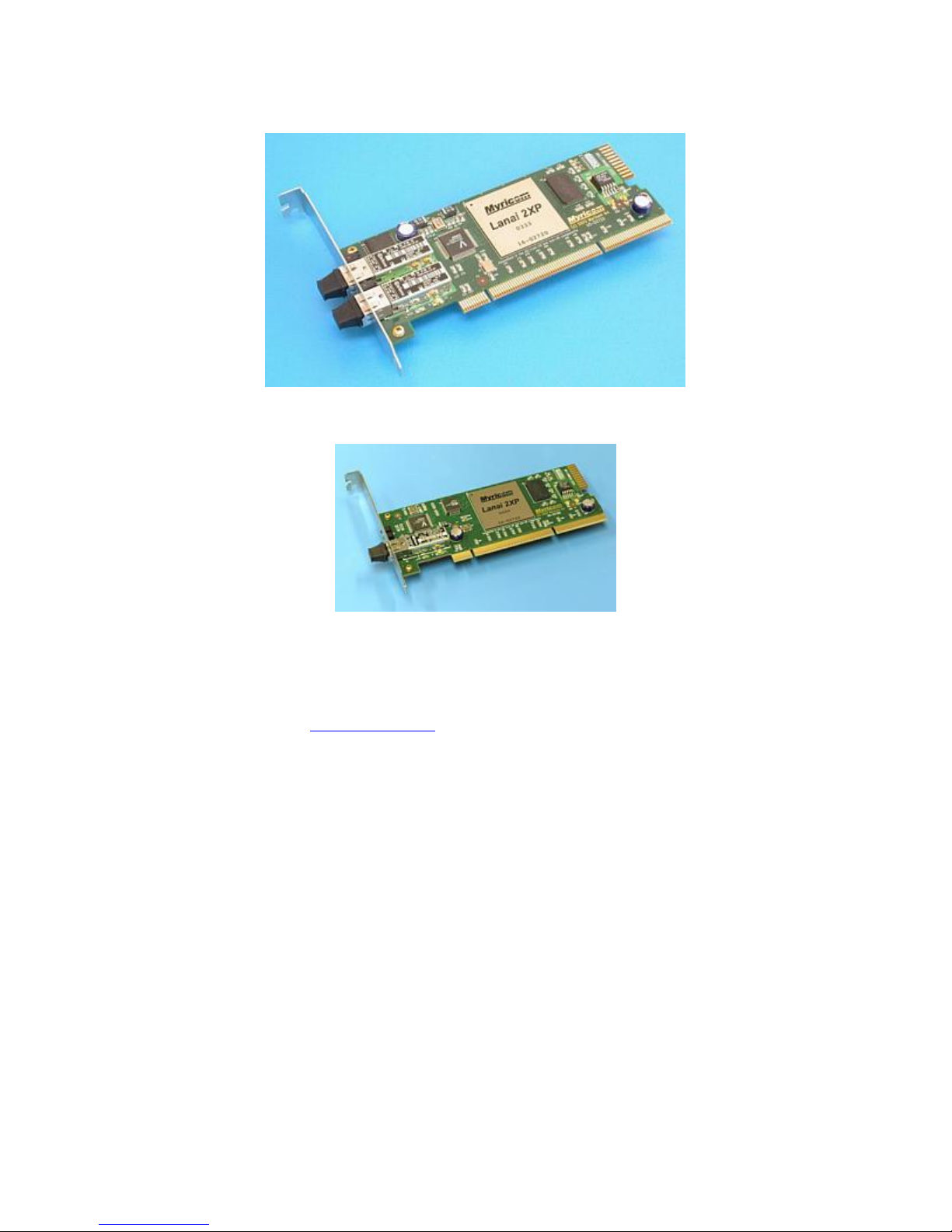
M3F2-PCIXE-2 two-port Myrinet-Fiber / PCI-X NIC with a standard PCI faceplate
M3F-PCIXF-2 Myrinet-Fiber / PCI-X NIC with standard PCI faceplate
These PCIX-series NICs operate in hosts with 75-133MHz PCI-X slots or 66MHz (3.3V)
PCI slots. The PCIXD NICs are also available as host-card adaptors (HCA) for the IBM
BladeCenter. Contact sales@myri.com for additional information on the IBM
BladeCenter HCAs.
© 2005 Myricom, Inc. DRAFT
4
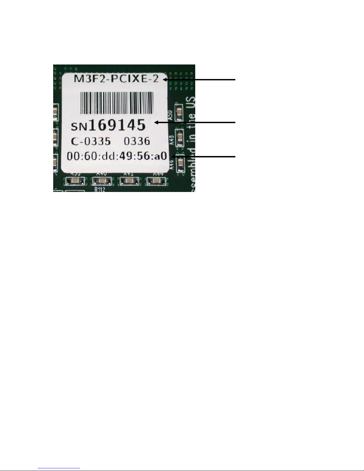
Identification on each Myrinet/PCI-X NIC
Product code
Serial number
Ethernet MAC
address
The label on a Myrinet/PCI-X NIC
A label similar to that above appears on the underside of every Myrinet/PCI-X NIC. This
label contains the product code, the serial number, and the Ethernet MAC address.
Please provide this information in any correspondence with Myricom support
(help@myri.com).
Installation
As a first step in using Myrinet technology, you must install the Myrinet/PCI-X NICs
into your hosts. Installation instructions vary depending on the characteristics of your
host: (1) tower unit host, or (2) rack-mounted host. If you have (1), you will need to use
the standard PCI faceplates, and if you have (2), you will need to use low-profile PCI
faceplates. Standard or low-profile faceplates must be specified at the time of order.
The NICs should be handled gently, preferably by the front panel or card edges. The
front panel of the NIC is the metal plate or molding (as can be seen on the photos above)
that contains two LEDs and the port connector(s). Directions for installation are as
follows:
Step 1: Power off the host to which you will be installing the NIC(s).
Remove the exterior covering of the machine, and locate the PCI-X
slot(s).
Note: Refer to the hardware specifications for the mother board to locate the PCI-X slots
(and distinguish a 64-bit PCI-X slot and a 64-bit PCI slot). If the mother board has more
than one PCI-X slot, identify which PCI-X slot(s) run at maximum speed (133MHz), and
© 2005 Myricom, Inc. DRAFT
5
which PCI-X slots share a PCI bus. To minimize the signal degradation between the
mother board and the NIC (and for best performance), we recommend that the
Myrinet/PCI-X NIC is inserted in the PCI-X slot closest to the PCI chipset. We also
recommend that the Myrinet/PCI-X NIC not share the PCI bus with another PCI device.
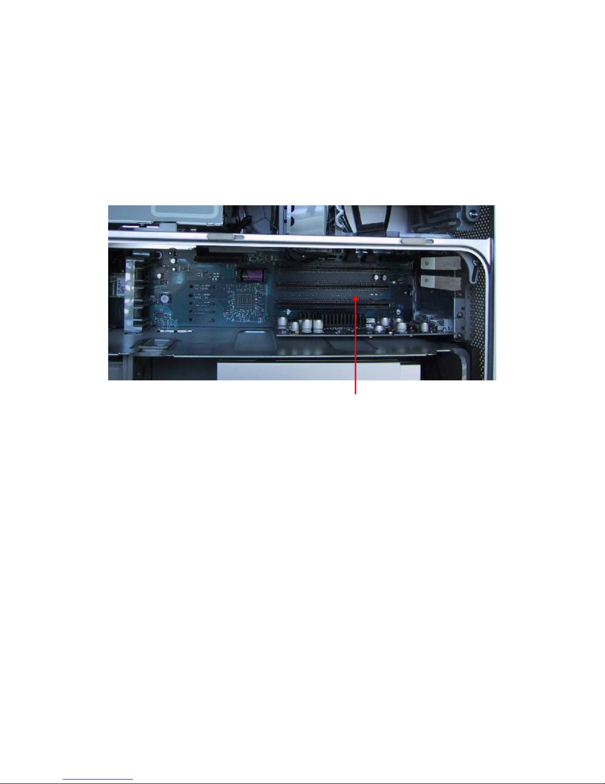
Case 1: Tower unit host
If you have a tower unit host, the PCI-X slots will look something like the
following:
PCI slot (64-bit)
In this photo the PCI slots are the long black connectors. There are four 64-bit
PCI slots.
Case 2: Rack-mounted host
If you have a rack-mounted machine, the PCI-X slots will look something like the
following:
© 2005 Myricom, Inc. DRAFT
6
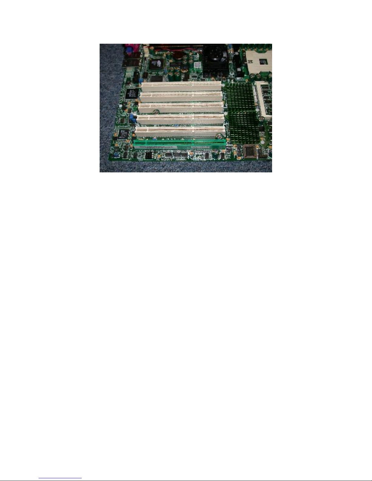
PCI-X slots on a rack-mountable mother board
In this photo, there are 6 PCI-X slots. One of the PCI-X slots is green, and the
remaining five PCI-X slots are white connectors.
Step 2: Insert the Myrinet/PCI-X NIC into a PCI-X slot.
Case 1: Tower unit host
With a tower unit host, a low-profile PCI-short-card Myrinet/PCI-X NIC with a
standard PCI faceplate is installed in a PCI-X slot. If your host has more than one
PCI-X slot, we recommend that the Myrinet/PCI-X NIC is inserted into the PCI-X
slot closest to the PCI chipset. For best performance, the Myrinet/PCI-X NIC
should be inserted into a PCI-X slot that runs at maximum speed (133MHz) and
should not share the PCI bus with another PCI device. Inasmuch as some PCI
connectors are more close-fitting than others, you may need to push quite hard on
the front panel and the edge of the card to seat the card securely.
© 2005 Myricom, Inc. DRAFT
7
 Loading...