

My Remote Manager UNIVERSAL GARAGE DOOR CONTROL User Manual
UNIVERSAL
GARAGE DOOR CONTROL
USER’S MANUAL ///
MyRemoteManager
PRODUCT DESCRIPTION ///
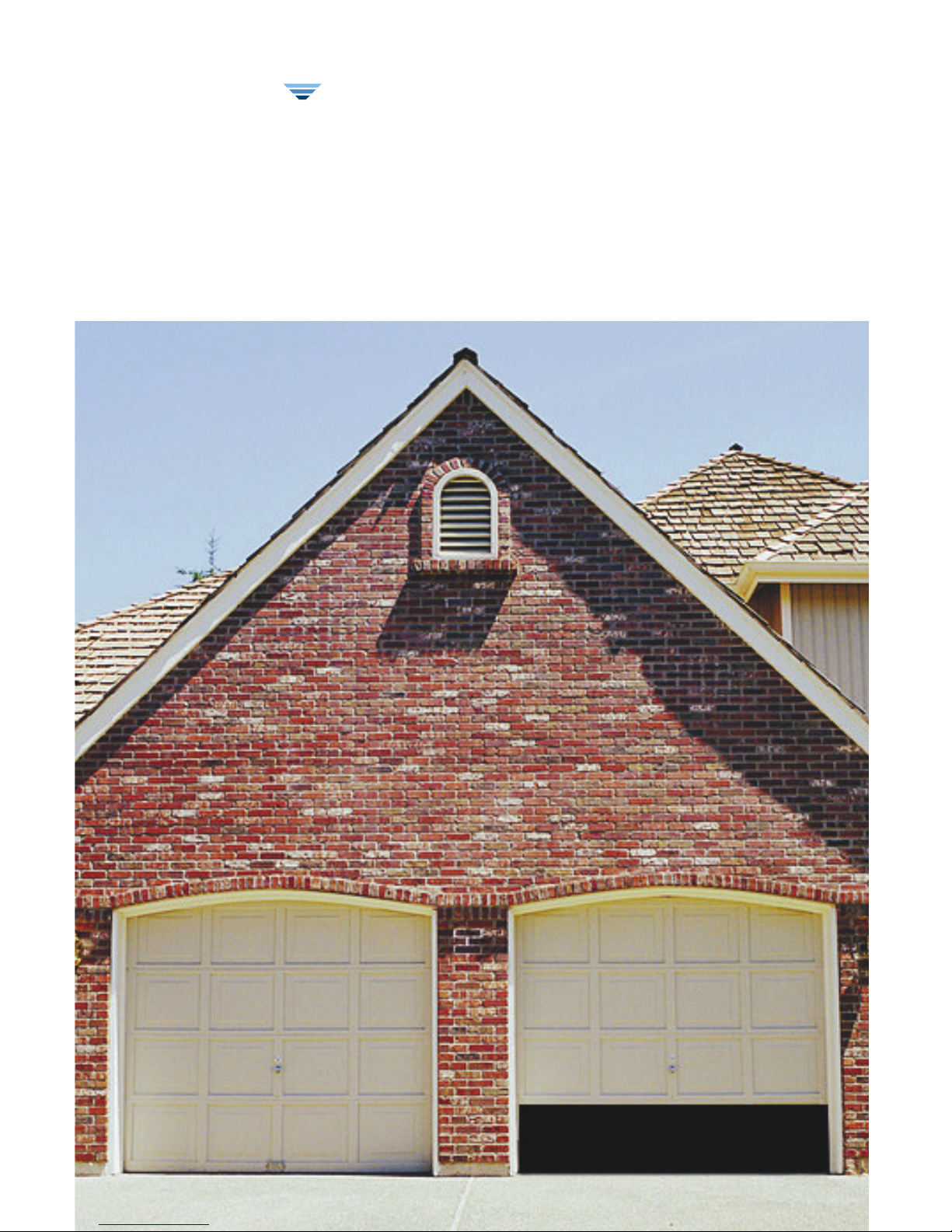
The Universal Garage Door Control allows you to know if your garage door has been opened or closed
by alerrting you via email and/or sms text messaging if the status has changed. It also allows you to
operate the garage door remotely from any PC or web-enabled mobile phone.
FIRST TIME SETUP ///
PREPARATION:
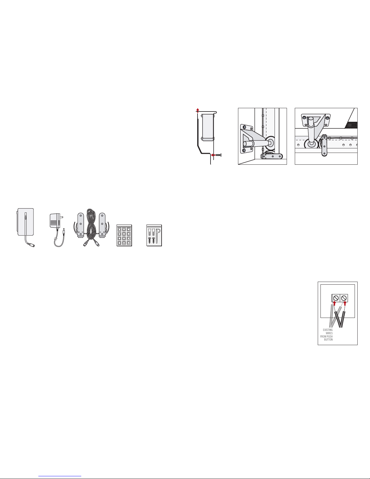
PACKAGE CONTENTS:
■
Universal Garage Door Control Unit
■
12V AC Power Supply
■
2 Switch Sensors and Connector Cables
■
Wall Mounting Kit with Discovery Tool
■
Stick-On Cable Tidy Clips
■
Documentation
HARDWARE INSTALLATION:
THE INSTALLATION OF THE SWITCHES:
The two Switch Sensors need to be installed on the right-hand garage door tracks.
One at the bottom of the track to sense the closed position and one on the horizontal portion
of the track to sense the open position.
1. Open your garage door.
NOTE: Make sure you remove power to your garage door opener to prevent
accidental operation during installation.
2. Carefully unwrap the Switch/Cable bundle.
3. Attach the Switch Sensor marked “CLOSED” in the following illustration on the lowest part of the
right-hand track. When the garage door is closed the lower guide wheel in the garage door
should press firmly on the actuator.
4. Using the stick-on cable tidy clips supplied, route the cable carefully on the back of the track
ensuring that the garage door operation does not interfere with the cable at any time.
(Please clean the area that you attach the cable tidy clips to ensure good adhesion of the clips)
Route the cable to a position close to your garage door motor.
5. Next, mount the switch marked “OPEN” as shown and route the cable carefully to the same position.
It is advised that you bundle the excess cable in a neat fashion and ensure that the cables
do not interfere or touch the garage door itself at any time.
THE INSTALLATION OF THE CONTROL UNIT:
1. Position the Universal Garage Door Control unit close to your garage door motor
(a space on the ceiling will be best).
2. Using the screws in the wall mounting kit. Affix the screws leaving 1/16” space between
the screw head and the object. Mount the Universal Garage Door Control unit onto the screws
and slide down to lock into place.
3. Attach the multi-connector tether from the unit to the cable harness plug.
4. Connect the two wires marked ‘DOOR SWITCH’ to the same terminals
that are connected to your door push button. These are usually found
on the rear side of the motor housing. Certain models may require
you to remove the cover to access the push button terminals.
You can attach either wire to either terminal.
5 Tidy all cabling and then attach the supplied Power Adapter to a
wall plug (in most cases there is a power outlet provided for the
garage door operator unit). Plug the AC jack in the white adapter
socket attached to the main cable harness.
6. You may now reconnect your garage door operator and proceed to Device Discovery.
I
2
UNIVERSAL GARAGE DOOR
CONTROL UNIT
SWITCH SENSORS WITH
CONNECTOR CABLES
12V AC
POWER SUPPLY
STICK-ON CABLE
TIDY CLIPS
WALL MOUNTING KIT WITH
DISCOVERY TOOL
‘CLOSED’ SWITCH SENSOR MOUNTED TO
LOWEST PART OF TRACK BY GARAGE FLOOR
REMOVE BOTTOM SCREW AND
THEN ATTACH TO TRACK USING
SCREW AND APPOPRIATE SLOT
‘OPEN’ SWITCH SENSOR MOUNTED TO UPPERMOST
PART OF TRACK ON GARAGE CEILING
PUSH BUTTON
TERMINALS
EXISTING
WIRES
FROM PUSH
BUTTON
WIRES FROM
UNIVERSAL
GARAGE DOOR
CONTROL UNIT
 Loading...