

Page 1

hyperion X5 - technical manual
Cod. 97070183
Rev. 00 05/2015
EN
www.my-ray.com
Page 2

Page 3

EN
TECHNICAL MANUAL
hyperion X5
Code Rev Date
97071183 00 15.05
Page 4

Page 5

TECHNICAL MANUAL - hyperion X5
PC CONFIGURATION ................................................................................................................................... 5
1.
1.1. SYSTEM REQUIREMENTS ...................................................................................................................... 5
1.2. SETTING UP THE DEVICE ...................................................................................................................... 6
1.2.1. PRELIMINARY OPERATIONS ........................................................................................................... 6
1.2.2. OPERATING SYSTEM SETTINGS .................................................................................................... 6
1.2.3. DISABLING WINDOWS FIREWALL ................................................................................................... 9
1.2.4. INTEL PRO 1000” NETWORK CARD INSTALLATION .................................................................... 10
1.2.5. ACQUISITION SERVER” SOFTWARE INSTALLATION .................................................................. 12
1.3. CONNECTION AND CONFIGURATION ................................................................................................ 17
1.3.1. SOFTWARE ACQUISITION SERVER .............................................................................................. 17
1.3.2. IRYS INSTALLATION AND CONFIGURATION................................................................................ 22
2. CALIBRATION ............................................................................................................................................. 28
2.1. PRELIMINARY OPERATIONS ............................................................................................................... 28
2.2. DEVICE CONFIGURATION .................................................................................................................... 29
2.3. XRAY ALIGNMENT ................................................................................................................................. 30
2.4. VERIFYING THE SENSOR CALIBRATION ............................................................................................ 34
2.5. VERIFYING THE MECHANICAL CENTERING ...................................................................................... 35
2.6. TEST LASER ........................................................................................................................................... 37
2.7. CALIBRATION DATA BACKUP .............................................................................................................. 40
3. CONTROL BOARDS DESCRIPTION .......................................................................................................... 41
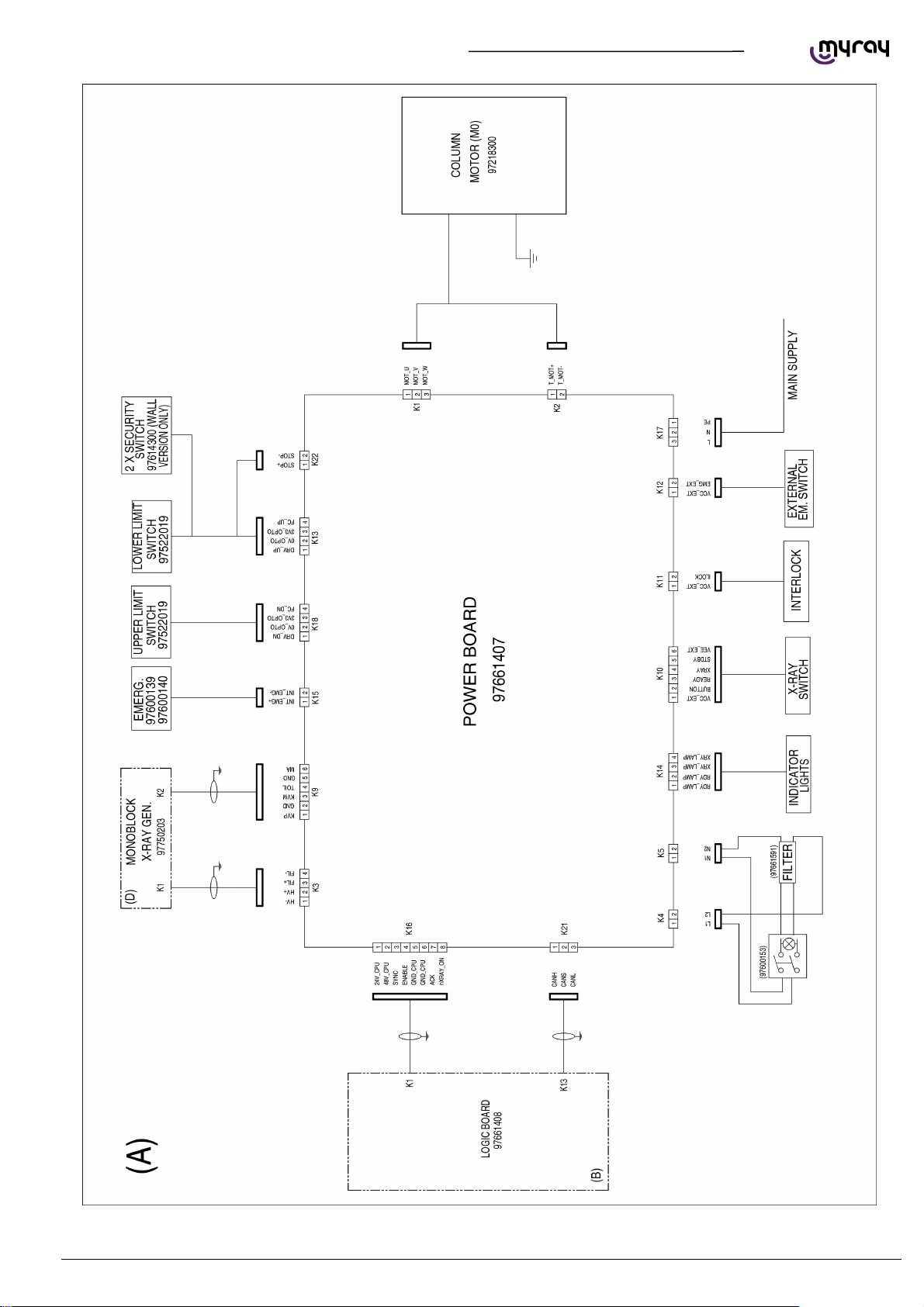
3.1. UNIT BLOCK DIAGRAM ......................................................................................................................... 41
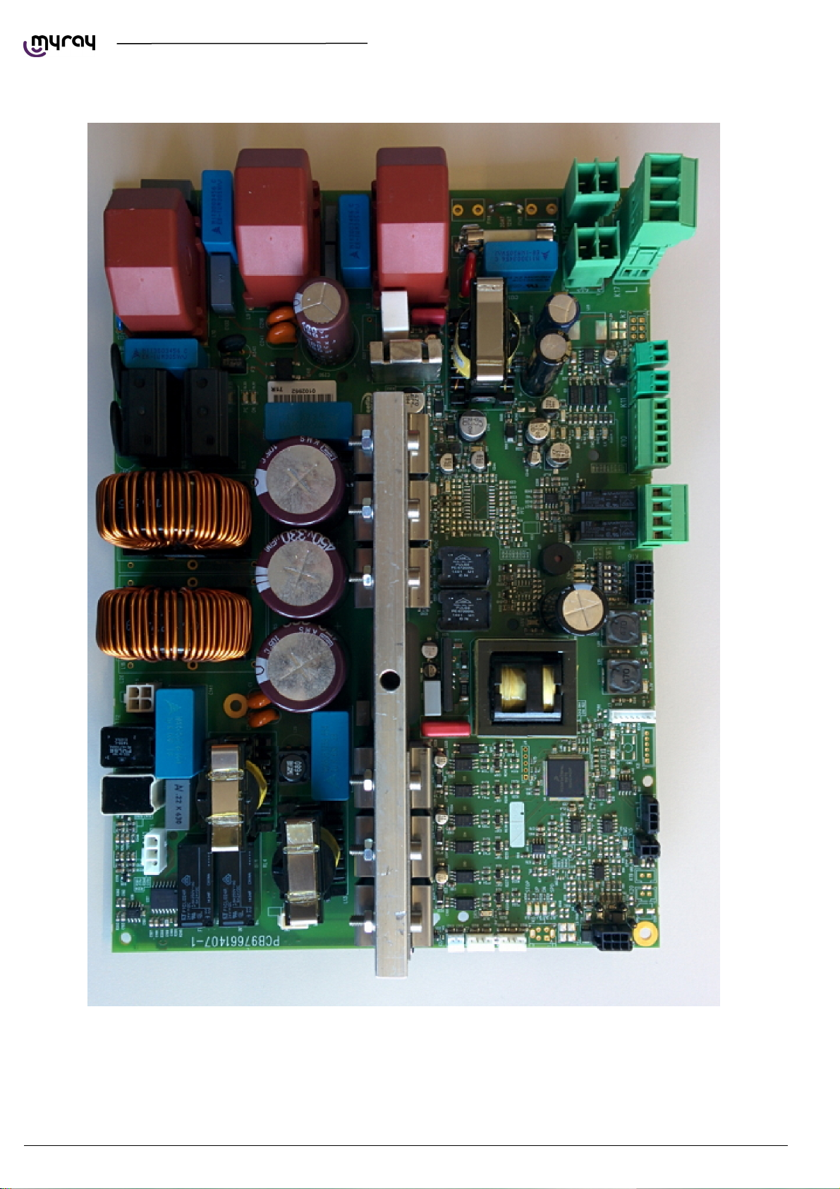
3.2. POWER BOARD 97661407 .................................................................................................................... 42
3.2.1. CONNECTORS LIST ........................................................................................................................ 44
3.2.2. FUSES AND DIP SWITCHES LIST .................................................................................................. 4 4
3.2.3. LEDS LIST ......................................................................................................................................... 44
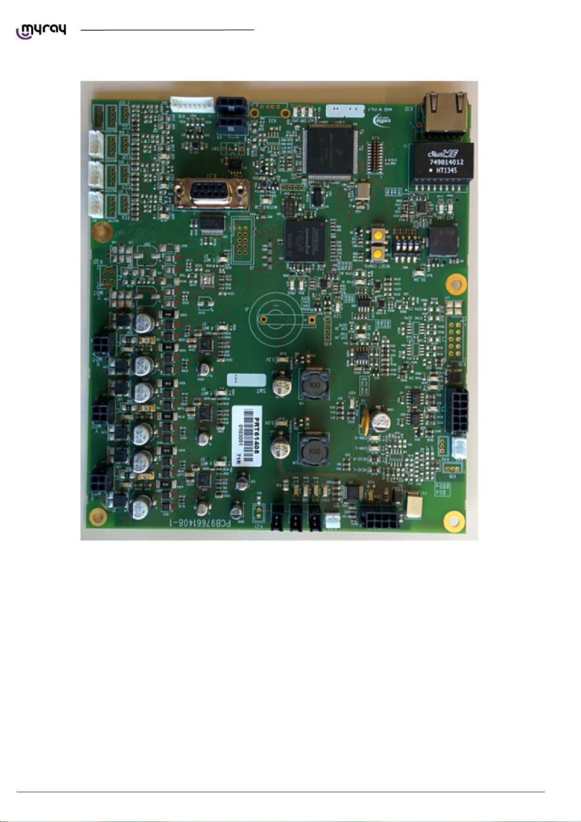
3.3. LOGIC BOARD 97661408 ....................................................................................................................... 46
3.3.1. CONNECTORS LIST ........................................................................................................................ 48
3.3.2. DIP SWITCHES LIST ........................................................................................................................ 48
3.3.3. LEDS LIST ......................................................................................................................................... 48
3.4. SENSOR INTERFACE BOARD 97661485 ............................................................................................. 50
3.4.1. CONNECTORS LIST ........................................................................................................................ 52
3.4.2. LEDS LIST ......................................................................................................................................... 52
3.5. KEYBOARD BOARD 97661484 .............................................................................................................. 52
3.5.1. CONNECTORS LIST ........................................................................................................................ 52
3.6. LOGO BOARD 97661539 ....................................................................................................................... 52
3.6.1. CONNECTORS LIST ........................................................................................................................ 52
EN
PC CONFIGURATION
3
Page 6

Page 7
A
A
A
A
A
A
A
TECHNICAL MANUAL - hyperion X5
1. PC CONFIGURATION
1.1. SYSTEM REQUIREMENTS
hyperion X5 needs two ethernet connections, one for generic communication purposes (this supports DHCP and can be
set up through the local network) and a second dedicate connection, which must set up as direct point-to-point between
the unit and the INTEL PRO 1000 network card on the PC.
The PC dedicate to image aquisition (from now on referred to as “Acquisistion server”) must respect the following system
specification. Such a PC can be purchased as an option directly from Cefla, the model is Lenovo ThinkCentre Edge 73
Tower.
System requirements:
PROCESSOR Intel H81, Intel Core i3 4150 (3.5GHz, 3MB L3 Cache, 1600MHz), Quad core
RAM 4GB
HD 500GB / 7200 rpm
DVD DVD+-RW DL
NETWORK 1 Eth Giga integrated + 1Intel(R) Gigabit CT Desktop Adapter PCI-e
O.S. WIN7 Pro 64bit
VIDEO CARD
POWER SUPPLY 500W
Besides the configuration above also the following ones have been validated and tested as “Acquisition Server” for X5:
COMPONENT CONFIG 1 CONFIG 2 CONFIG 3 CONFIG 4
PROCESSOR 1 CPU INTEL XEON
POWER SUPPLY >= 800 W >= 550 W >= 600 W >= 400 W
VIDEO CARD ATI RADEON HD 7770 OC GHZ EDIT. VAPORX 1GB GDDR5 ATI RADEON R7
HARD DISK 2 SATA HDD - 300
RAM 4 GB DDR3 8 GB DDR3 1600 MHZ
O.S. WINDOWS 7 PROFESSIONAL 64 BIT SP1
NETWORK 2 ETHERNET CARDS (AT LEAST ONE INTEL PRO -1000 )
OTHER MINIMUM SCREEN RESOLUTION 1280X1024, 64 MILLION COLORS
The following video cards have been tested and validated for use with hyperion X5:
VIDEO CARDS MINIMUM POWER SUPPLY
TI Radeon HD 4850 / 5770 – 1GB >= 450 W
TI Radeon HD 4870 / 4890 / 5850 / 5870 – 1GB >= 500 W
Sapphire Radeon HD 6750 / 6770 – VaporX – 1GB –
RAM GDDR5
Sapphire Radeon HD 6850 / 6870 / 6950 / 7870 – VaporX
– 1GB – RAM GDDR5
Sapphire Radeon HD 7770 – GHz Ed. - OC - VaporX –
1GB – RAM GDDR5
Sapphire Radeon HD 6970 – VaporX – 2GB – RAM
GDDR5
Sapphire Radeon HD 7850 - 1GB / 2GB - RAM GDDR5 >= 500 W
Sapphire Radeon HD 7870 - 2GB - RAM GDDR5 >= 500 W
Sapphire Radeon HD 7750 - OC - 1GB – RAM GDDR5 >= 400 W
MD FirePro W7000 – 4GB GDDR5 >= 400 W
MD/Sapphire Radeon R7 250 1GB – RAM GDDR5 >= 400 W
MD/Sapphire Radeon R7 260X - RAM 1GB DDR5 >= 500 W
MD/Sapphire Radeon R9 270 - RAM 2GB DDR5 >= 500 W
MD Radeon HD 7450 PCI Express 2.0, 128 Bit, 1024 MB, DDR3
E5-2630 - 2,3GHZ 6 CORE
1 CPU INTEL I7 3770
- 3,4 GHZ – 4 CORE
1 CPU INTEL XEON
E5-1620 - 3.60 GHz 4 CORE
1 SATA HDD - 500 GB - 10K RPM
GB - 10K RPM
DVD+-RW DL
>= 450 W
>= 500 W
>= 500 W
>= 550 W
1 CPU INTEL XEON
E3-1270 V3 – 3.50
GHz – 4 CORE
250 1GB
EN
PC CONFIGURATION
5
Page 8
TECHNICAL MANUAL - hyperion X5
1.2. SETTING UP THE DEVICE
1.2.1. PRELIMINARY OPERATIONS
The acquisition server must comply to the system requirements detailed above. If provided from Cefla, the complete
software comes preinstalled, otherwise it will be strictly mandatory to choose a compliant PC and install the software
correctly.
The 2 network adapters on the acquisistion server are needed for communication with the hyperion X5.
One of these network adapters is used for a direct connection with the image detector on the X5.
If the acquisition server is not purchased from Cefla, the network adapter will be provided in the accessories box of the
hyperion X5 and will need to be installed and configured on site.
The dedicated network adapter is an Intel Pro 1000 and will need a free PCI-E slot on the motherboard of the acquisition
server to be installed.
The only supported operating system for the acquisition server is WINDOWS 7 PRO 64 bit. The Intel Pro 1000 will be
automatically recognized by the operating system and drivers will be installed automatically.
The acquisition server must be accessed with an Administrator level user account.
IMPORTANT: for up to date video card drivers please refer to Cefla's extranet website.
The Microsoft .NET Framework 4.0 are required for the software to work and will be installed together with the video
card drivers.
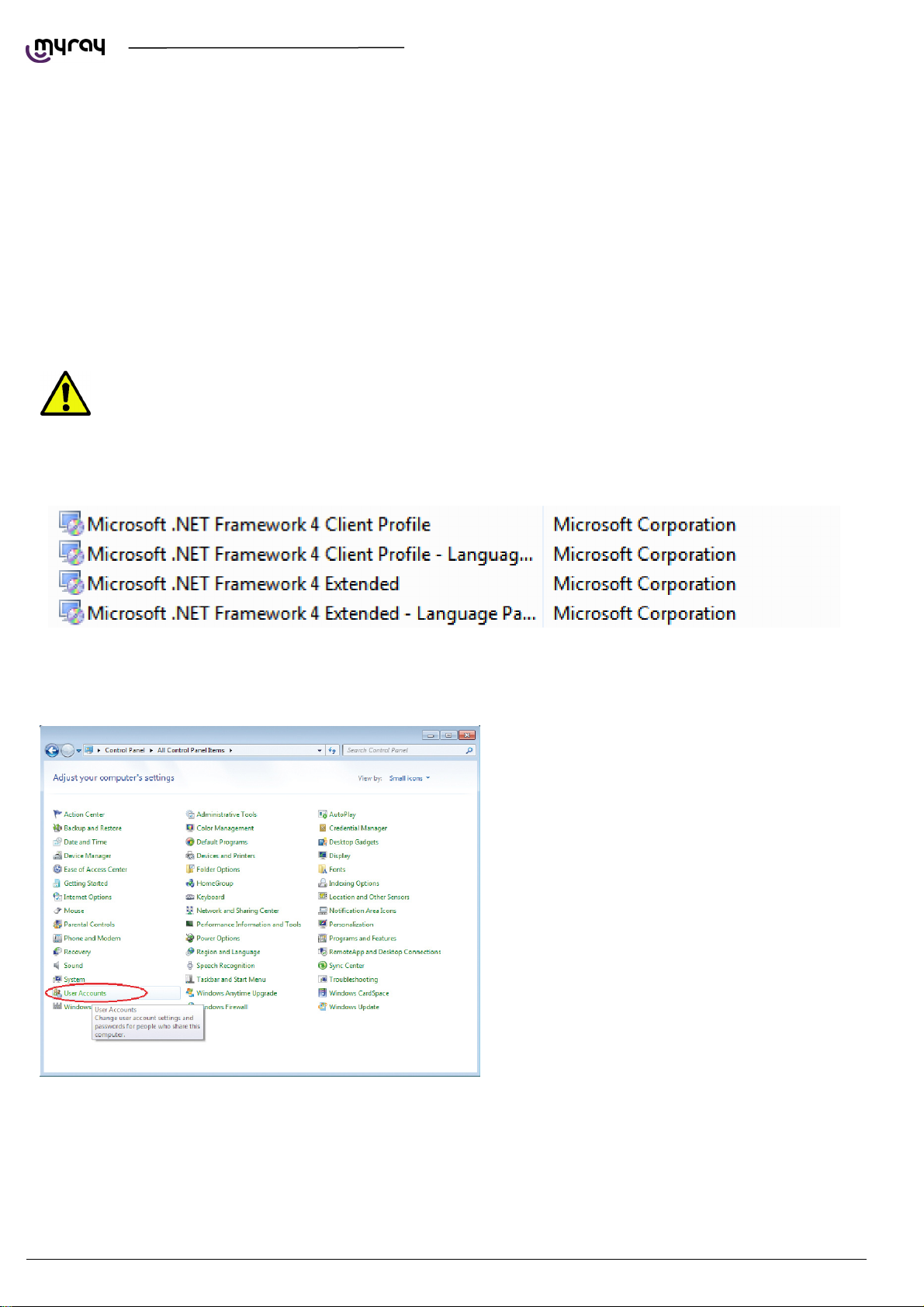
Please make sure that the following entries are present in the installed programs list:
If the libraries were not installed automatically, please download them from the Microsoft website and install them
manually.
1.2.2. OPERATING SYSTEM SETTINGS
”.
Open the Control Panel , select “User
Account”and then “Change User Account Control
Settings”.
6
PC CONFIGURATION EN
Page 9
TECHNICAL MANUAL - hyperion X5
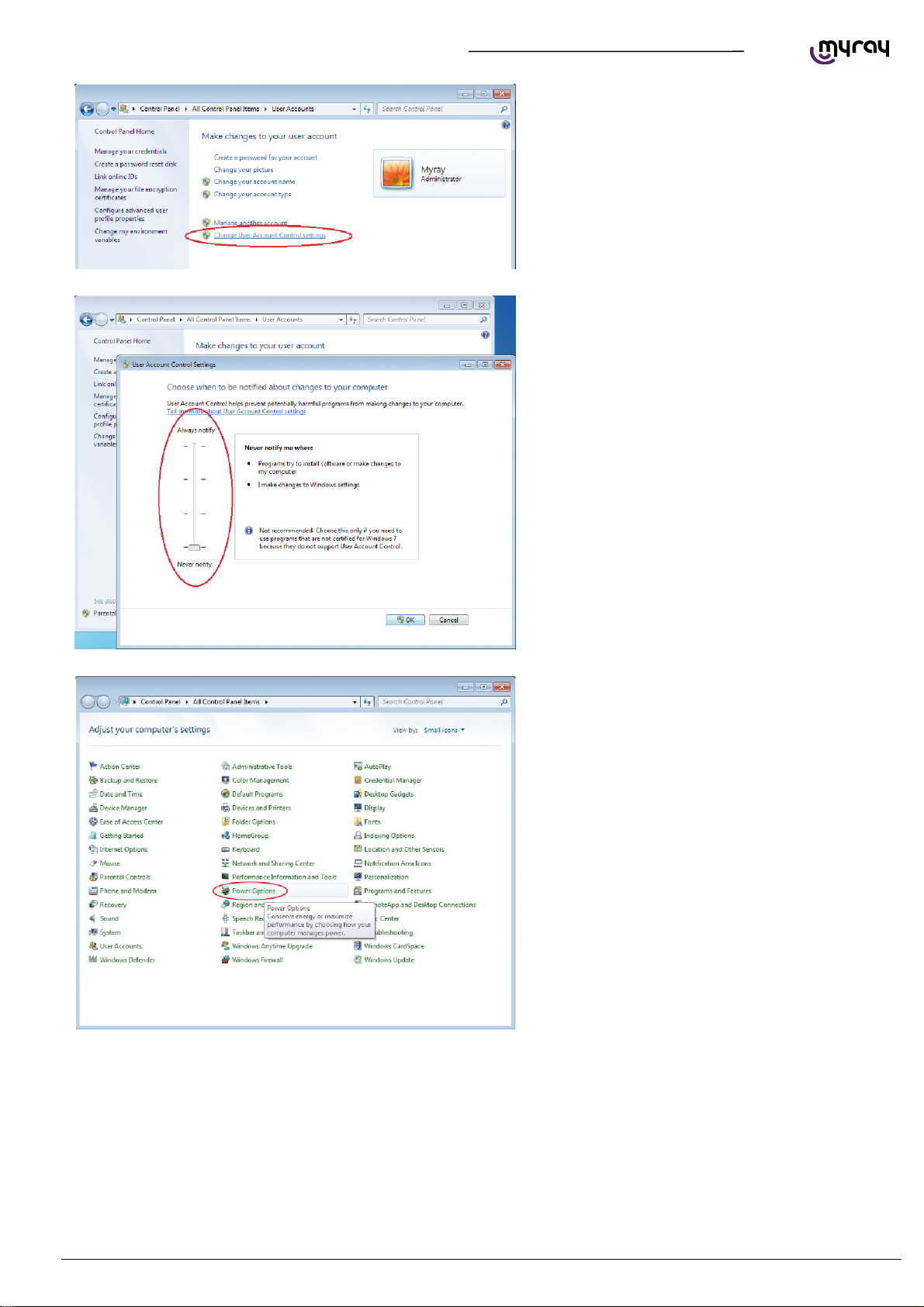
Select the lowest notification level “Never Notify”.
RESTART THE PC.
From the Control Panel select “Power Options”.
EN
PC CONFIGURATION
7
Page 10
A
TECHNICAL MANUAL - hyperion X5
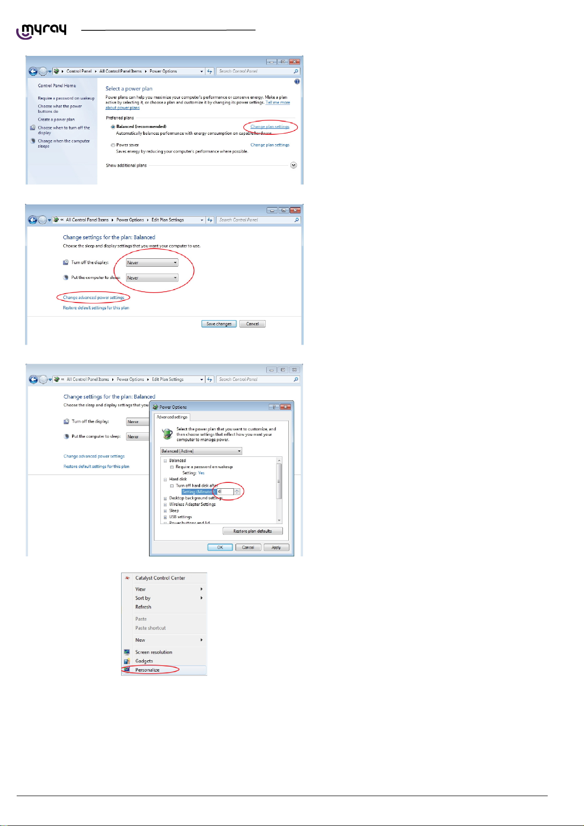
On the “Balanced”profile select “Change plan
settings”.
Set“Turn OFF display”and“Put the computer to
sleep”to“Never”. Select “Change advanced power
settings”.
Set“Hard disk Turn OFF hard disk after 0”.
8
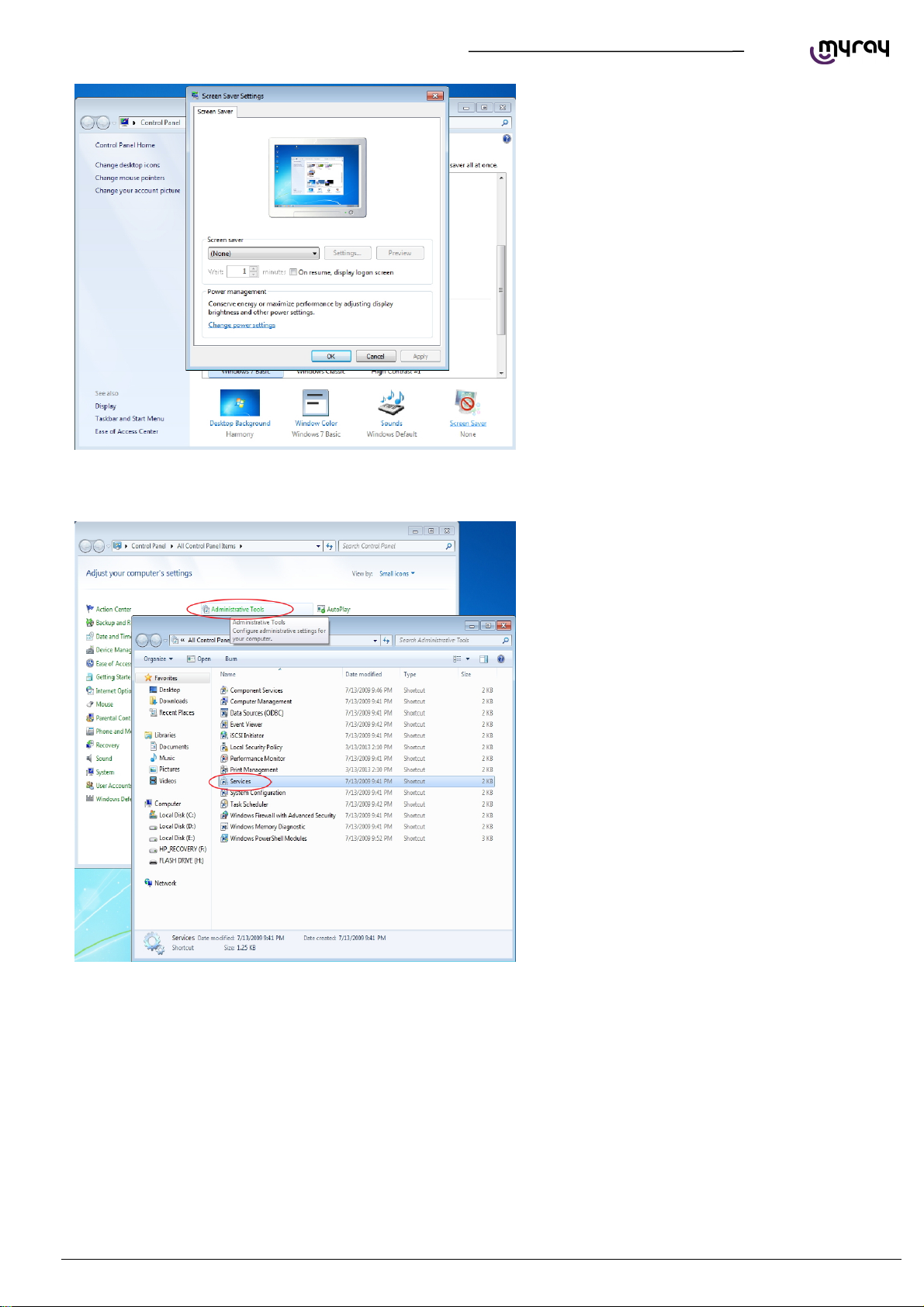
lso deactivate any screensaver. To do this right
click on the mouse on any icon-free desktop or
window area and select “Personalize” from the
menu.
PC CONFIGURATION EN
Page 11
A
TECHNICAL MANUAL - hyperion X5
lso deactivate any screensaver. To do this right
click on the mouse on any icon-free desktop or
window area and select “Personalize” from the
menu.
1.2.3. DISABLING WINDOWS FIREWALL
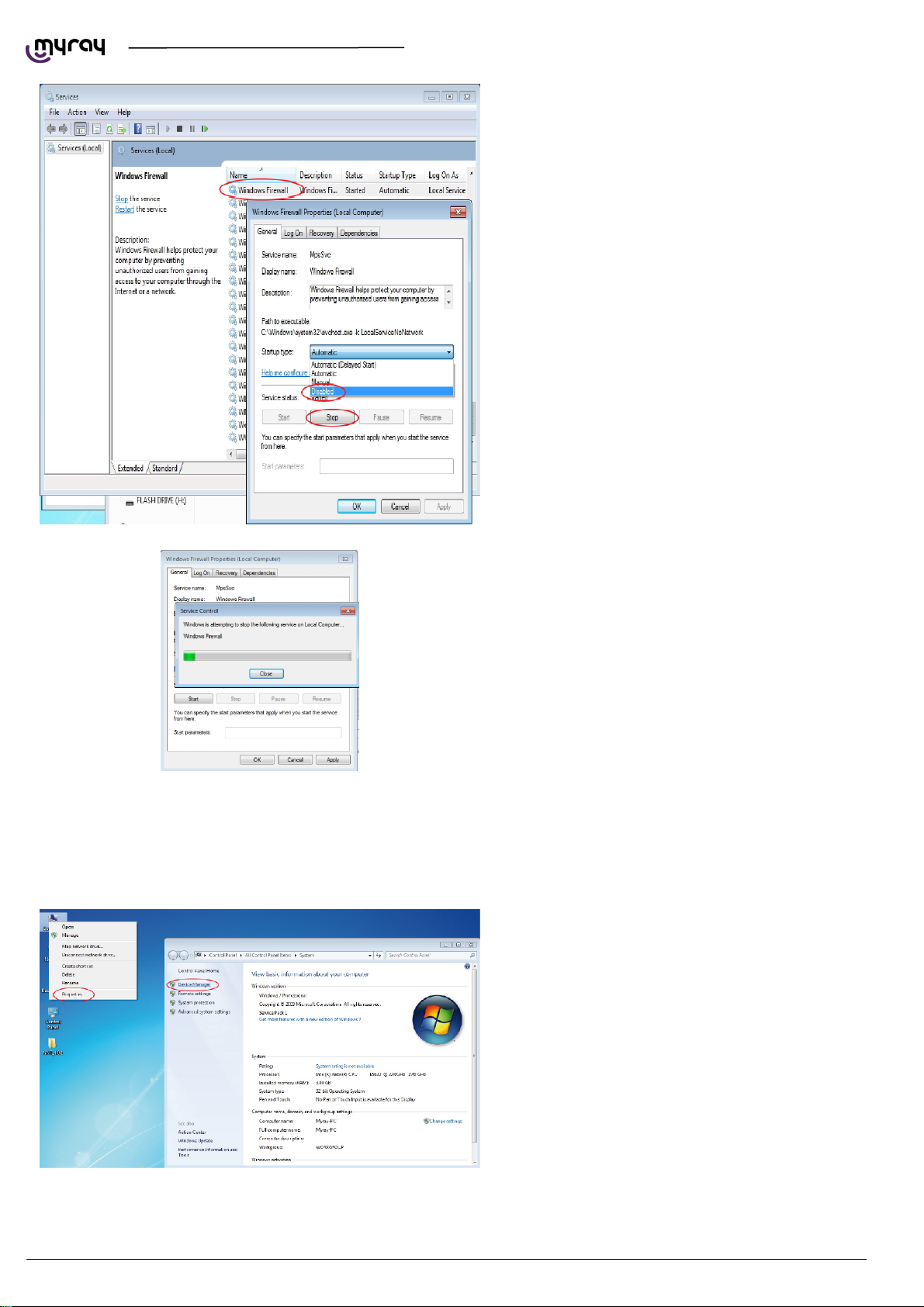
From the Control Panel select “Administrative
Tools” and double click on “Services”:
EN
PC CONFIGURATION
9
Page 12
TECHNICAL MANUAL - hyperion X5
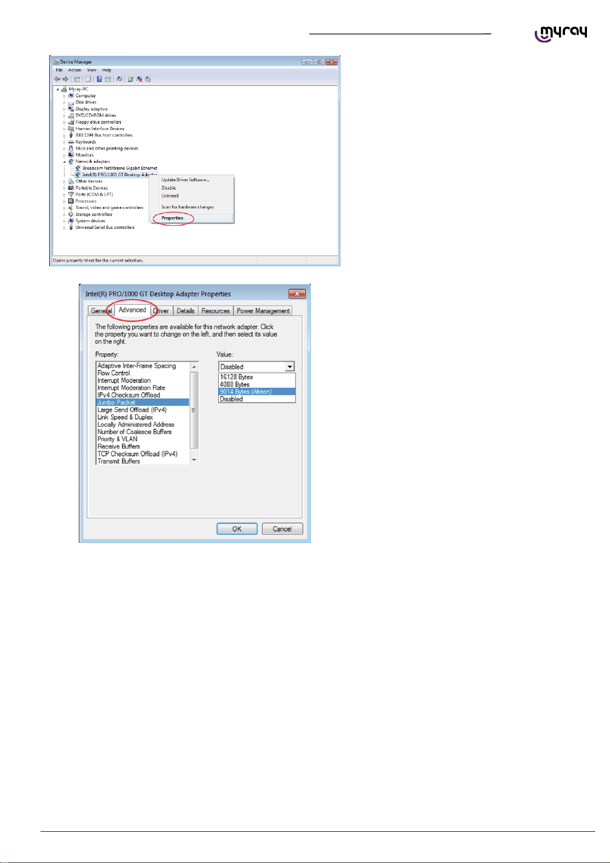
Scroll down the service list, right click on the
“Windows firewall” service and double click.
Go to the “Startup type” drop-down menu and
select “Disabled”. Then press the “Stop” key to
stop the service currently being executed.
Wait until the service is stopped:
Click on “OK” to close the dialogue window.
From the Windows Services list, search for “Windows update”, stop the service and disable the automatic startup.
1.2.4. INTEL PRO 1000” NETWORK CARD INSTALLATION
Right click with the mouse on “Computer”, select
“Properties” and select “Device Manager” in the
left column.
10
PC CONFIGURATION EN
Page 13
TECHNICAL MANUAL - hyperion X5
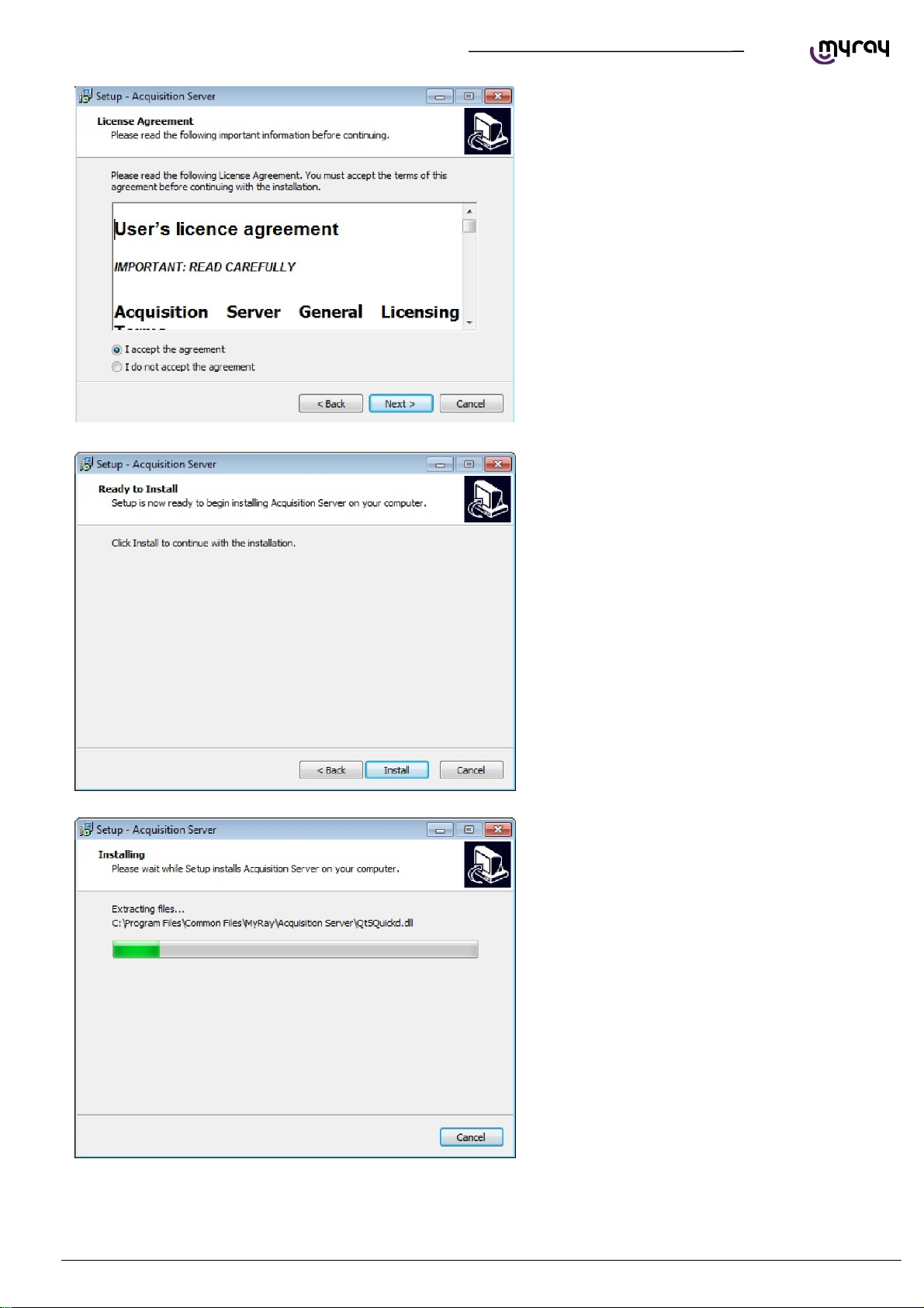
Expand the “Newtork Adapter” group, right click
on the “Intel pro 1000”, and select “Properties”.
Select the “Advanced” tab, highlight the “Jumbo
Packet”, and set it to “9014 byte
EN
PC CONFIGURATION
11
Page 14

TECHNICAL MANUAL - hyperion X5
From the “Advanced” tab set the “Receive Buffers”
parameter to 2048
WARNING: the “Receive Buffers” parameter migh not show on this window. If not visible, please search
for the “Performance options” parameter, click on “Properties” and set the “Receive bufffers” value from
there.
1.2.5. ACQUISITION SERVER” SOFTWARE INSTALLATION
This software can only be installed on 64 bit
Operating Systems.
Launch the software installer (from the setup
menu on the usb dongle or from Extranet
download)and select the language:
Click on “Next”
12
PC CONFIGURATION EN
Page 15
TECHNICAL MANUAL - hyperion X5
Select “I accept” , then click “Next”
Click on “Install”
Wait
EN
PC CONFIGURATION
13
Page 16
A
TECHNICAL MANUAL - hyperion X5
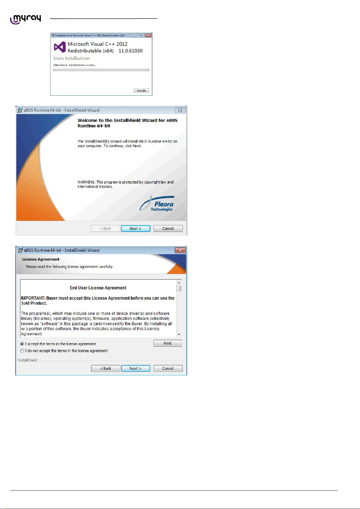
Installed software will be checked, any missing
system component will be installed at this stage.
The Pleora driver for the Intel Pro 1000 network
adapter will be installed automatically, click “Next”
ccept and click “Next”
14
PC CONFIGURATION EN
Page 17
TECHNICAL MANUAL - hyperion X5
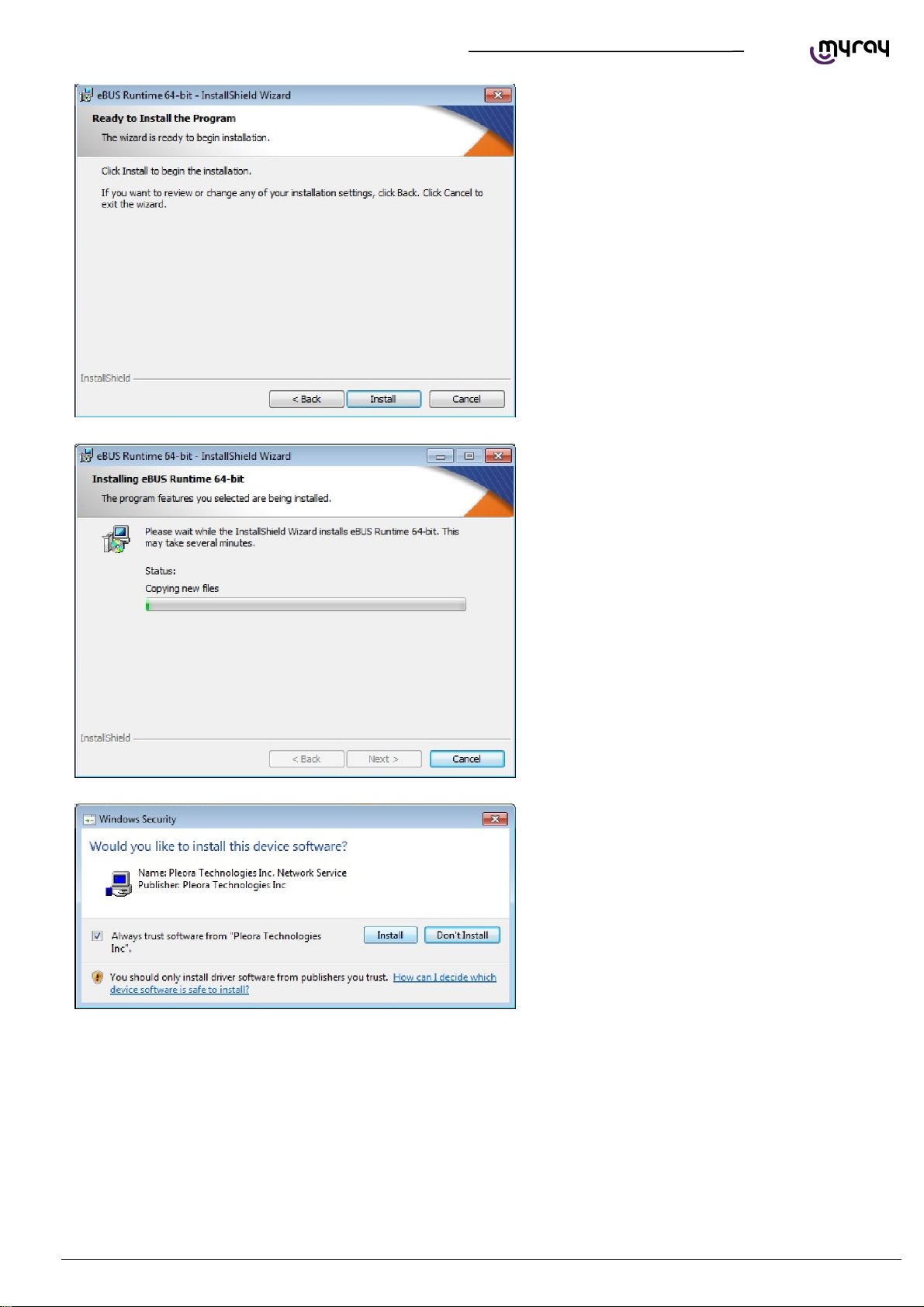
Click on “Install”
Wait for the driver installation to finish.
If the following window is displayed, select
“Always Trust” and click “Install”
EN
PC CONFIGURATION
15
Page 18
TECHNICAL MANUAL - hyperion X5
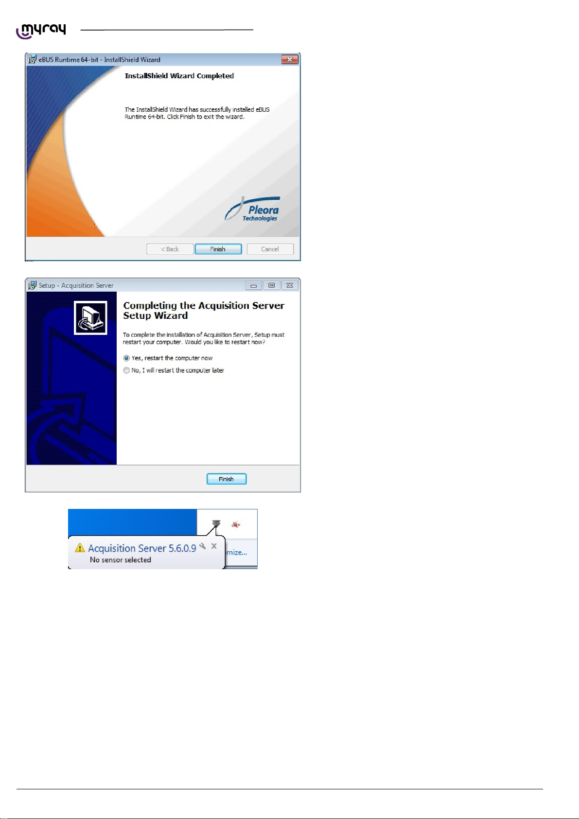
Click “Finish” at the end of the installation.
Restart the PC
The “Acquisition server” software will start up
automatically and will be accessible from the
system tray.
16
PC CONFIGURATION EN
Page 19
TECHNICAL MANUAL - hyperion X5
1.3. CONNECTION AND CONFIGURATION
1.3.1. SOFTWARE ACQUISITION SERVER
hyperion X5 can be connected to a LAN or direclty to the Acquisistion server PC. Either way, the image detector must be
connected directly with a point-to- point connection to the Acquisition Server PC.
The direct connection between the image detector and the PC is managed automatically by the software, there is thus no
need to set the IP address on the detector for the connection to be estabilished. The Intel Pro 1000 always stays
configured as from system default (DHCP) and the connection is managed automatically.
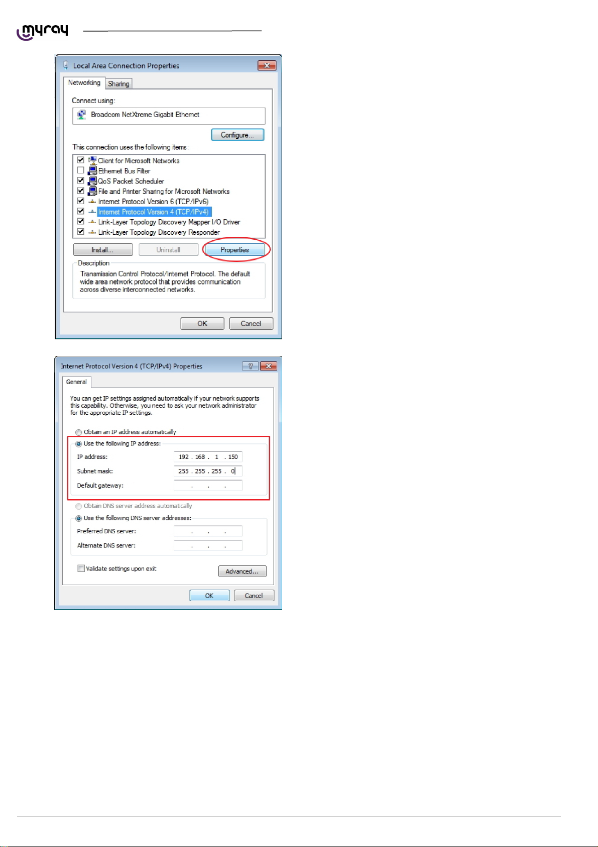
It could be necessary to set up a static IP address for the network adapter used for the PC to hyperion X5 system
communication. If this network adapter is directly connected to the unit, the IP address for the PC should be set to one in
the same subnet as the hyperion X5's default (e.g.192.168.1.150)
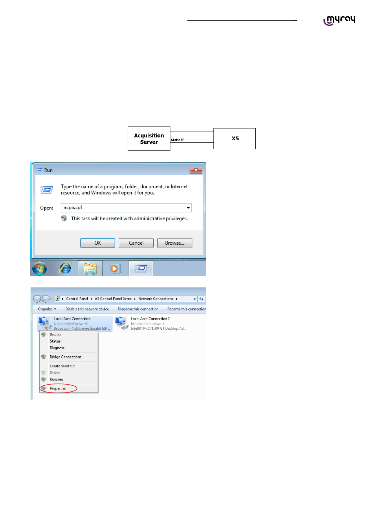
To set a static IP address on a network board it is
necessary to click on the Start button, type
“ncpa.cpl” and press Enter. The Network
connection window will open:
If it is necessary to give the communication
network board a fixed IP address , right-click with
the mouse on the relative connection (not the
INTEL pro 1000 one, the one supplied by the
other network board) and select “Proprieties”.
EN
PC CONFIGURATION
17
Page 20
TECHNICAL MANUAL - hyperion X5
Select “Protocol internet version 4
(TCP/IPv4)”and click on “Properties”.
Specify an IP address compatible with the one of
the X9. In the “IP Address” field, type an address
as 192.168.1.XXX where XXX can be a digit
included between 1 to 254, with the exception of
the X9 default IP (usually 160). The Subnet mask
will be automatically filled.
Confirm by pressing the “OK” button.
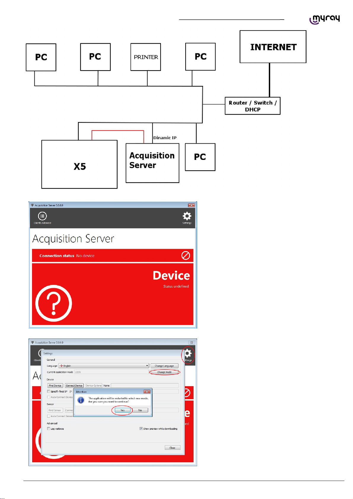
If the unit is connected to a LAN with DHCPC (as in the following diagram) then the noetwork adapter should be set to
“Obtain IP address automatically”. The DHCP server will assign correct IP addresses to both the hyperion X5 and the
acquisistion server.
18
PC CONFIGURATION EN
Page 21
TECHNICAL MANUAL - hyperion X5
Once the IP addresses have been configured
correctly you can start setting up the Acquisistion
Server software.
Click on the Acquisition Server icon in the system
tray, the main window will be magnified in “User”
mode.
The topmost red area represents the connection
status and the sensor status. The lower red area
is used for diagnostics and reporting error
messages.
Click on the “Settings” icon on the top left corner.
The connections and options panel will open up.
Select “Change mode” and confirm the application
restart request.
EN
PC CONFIGURATION
19
Page 22
TECHNICAL MANUAL - hyperion X5
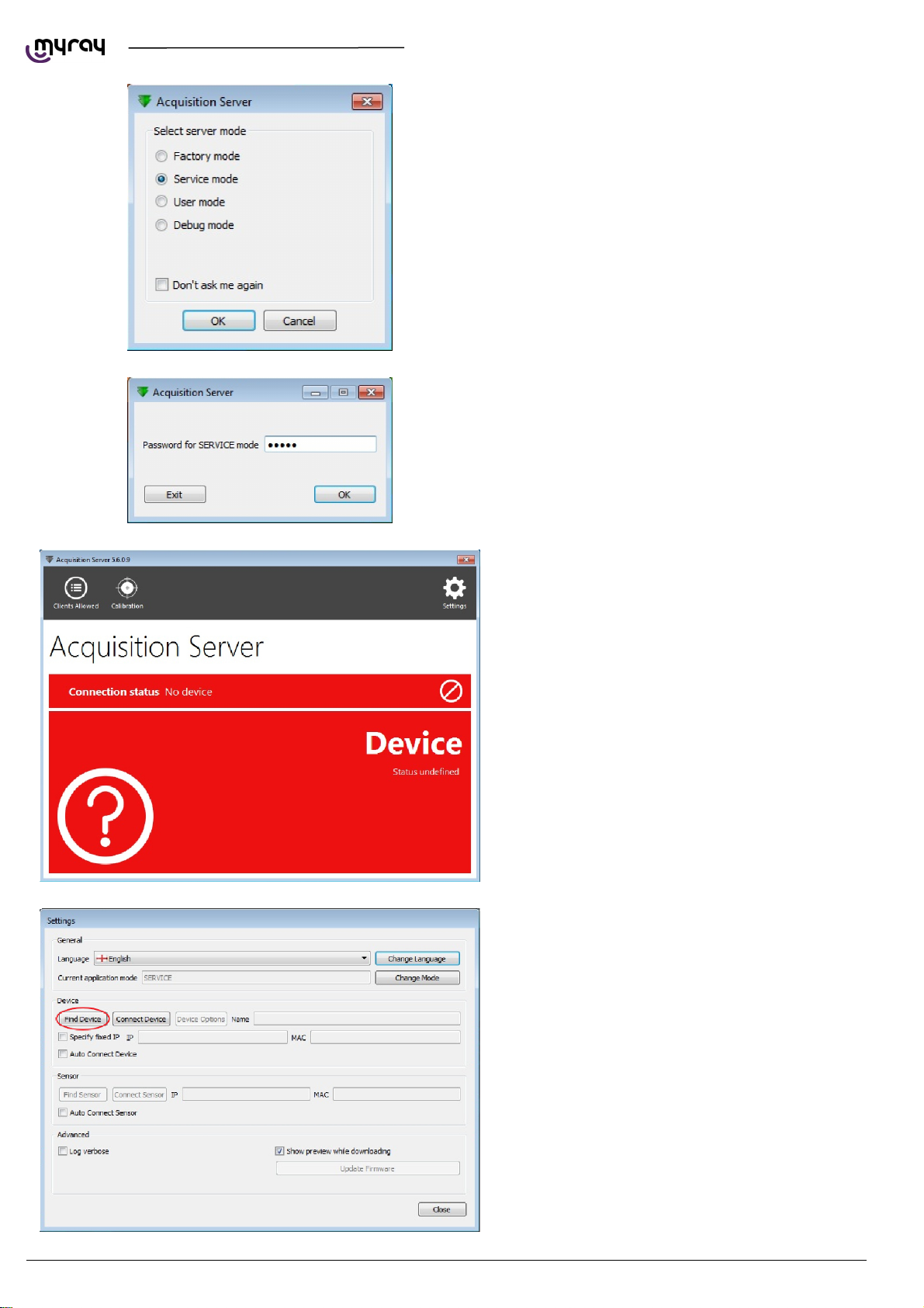
On program restard you'll be prompted to select
the application mode. Select “Service mode”.
enter the password “cefla”.
Restart the “Acquisition Server” software, now in
“Service mode”.
20
Click on “Settings” and select “Find Device”.
PC CONFIGURATION EN
Page 23
TECHNICAL MANUAL - hyperion X5
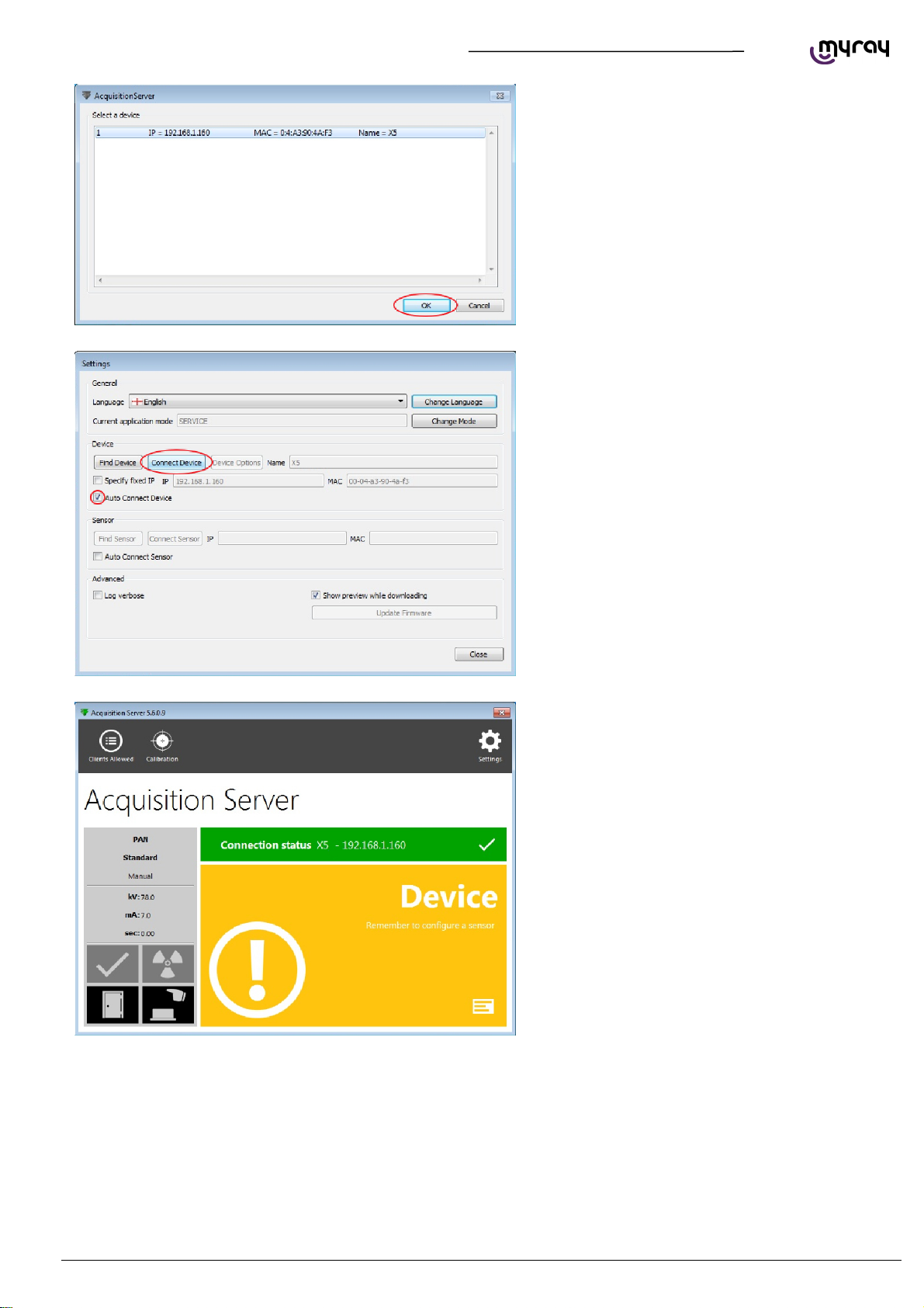
hyperion X5 X5 will be found, select the line and
continue.
Select “Connect Device” and activate the “Auto
connect device” option. Click on “Close”.
In a few seconds the connection to the hyperion
X5 will be estabilished.
EN
PC CONFIGURATION
21
Page 24
TECHNICAL MANUAL - hyperion X5
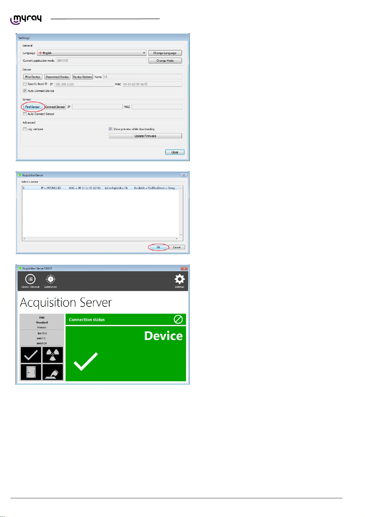
Now the link to the image detector needs to be
estabilished. Click on “Settings” and then on “Find
Sensor”.
The image detector will be detected automatically.
Select the line and confirm by clicking “OK”.
The acquisistion server should show full green
status now:
1.3.2. IRYS INSTALLATION AND CONFIGURATION
The imaging software used with Hyperion X5 is “iRys” (version 5.5 or later), installed in “Station” version.
It is not strictly necessary to install iRys on the Acquisistion Server PC, iRys can be installed on any PC in the network
that could communicate with the Acquisition Server PC.
22
PC CONFIGURATION EN
Page 25
TECHNICAL MANUAL - hyperion X5
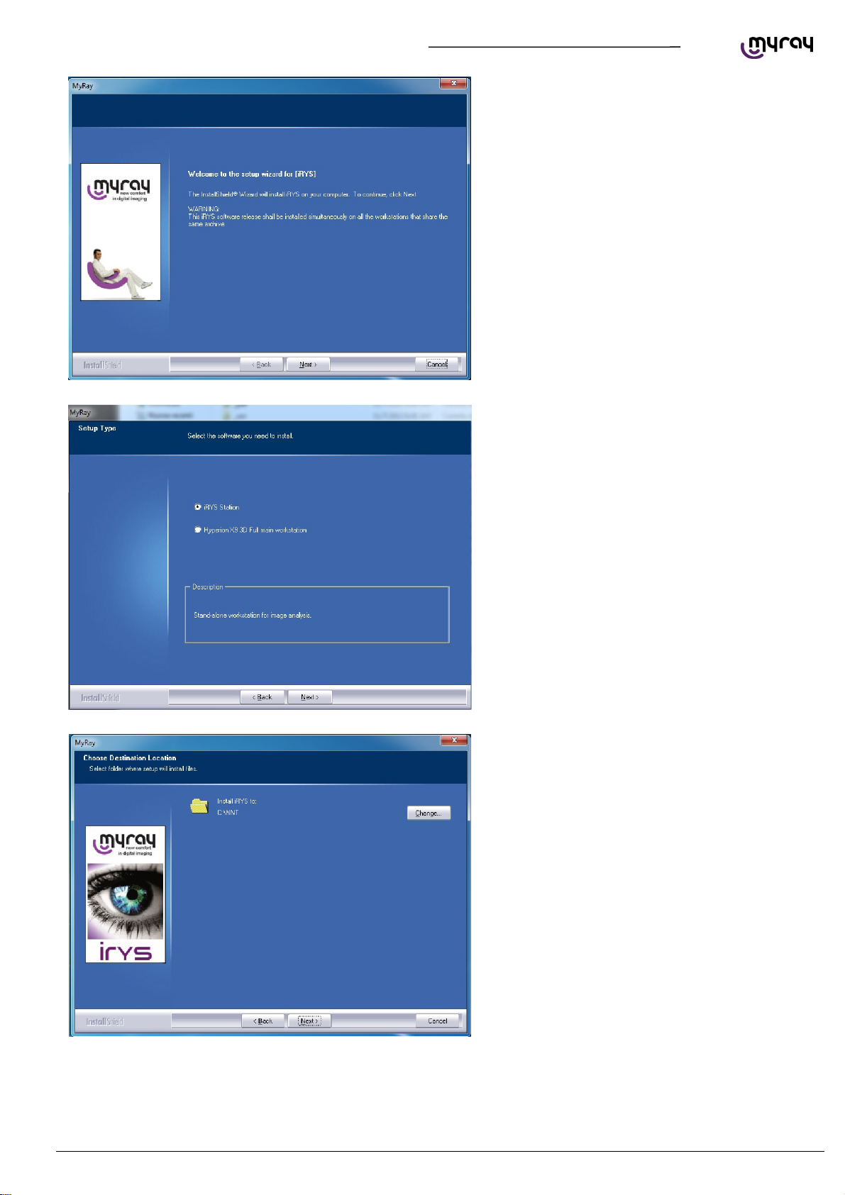
Load the Irys installation CD and follow the
instructions on the screen.
Select “IRYS Station” installation:
Continue by confirming the installation path:
EN
PC CONFIGURATION
23
Page 26
TECHNICAL MANUAL - hyperion X5
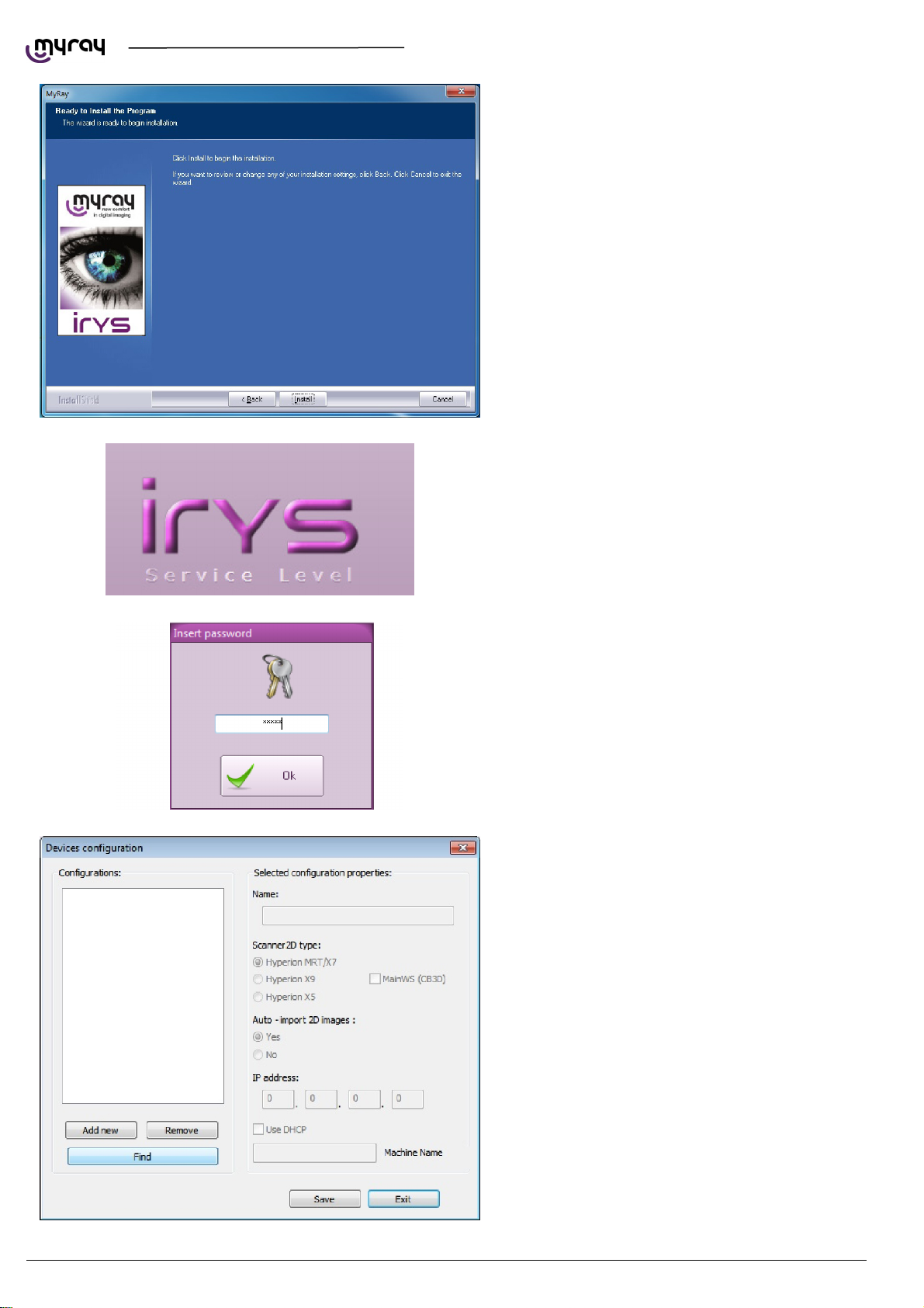
Click “Install”:
Click ok to confirm.
To connect the hyperion X5 to iRYS, start iRYS
and press “CTRL + ALT + SHIFT + FINE”
simultaneously to access the
service level of the program, confirmed by the
message in the bottom right-hand corner:
Now press “ALT + F10” and type the password
“12345” to access the device configuration panel:
By clicking on “Find” the PC running the
Acquisition Server software will be detected.
WARNING: iRys connects to the Acquisition
Server software and not to the hyperion X5
directly, so the IP address shown in this window is
not the hyperion X5 IP address, but the
Acquisition Server PC address.
Select the line and confirm.
24
PC CONFIGURATION EN
Page 27
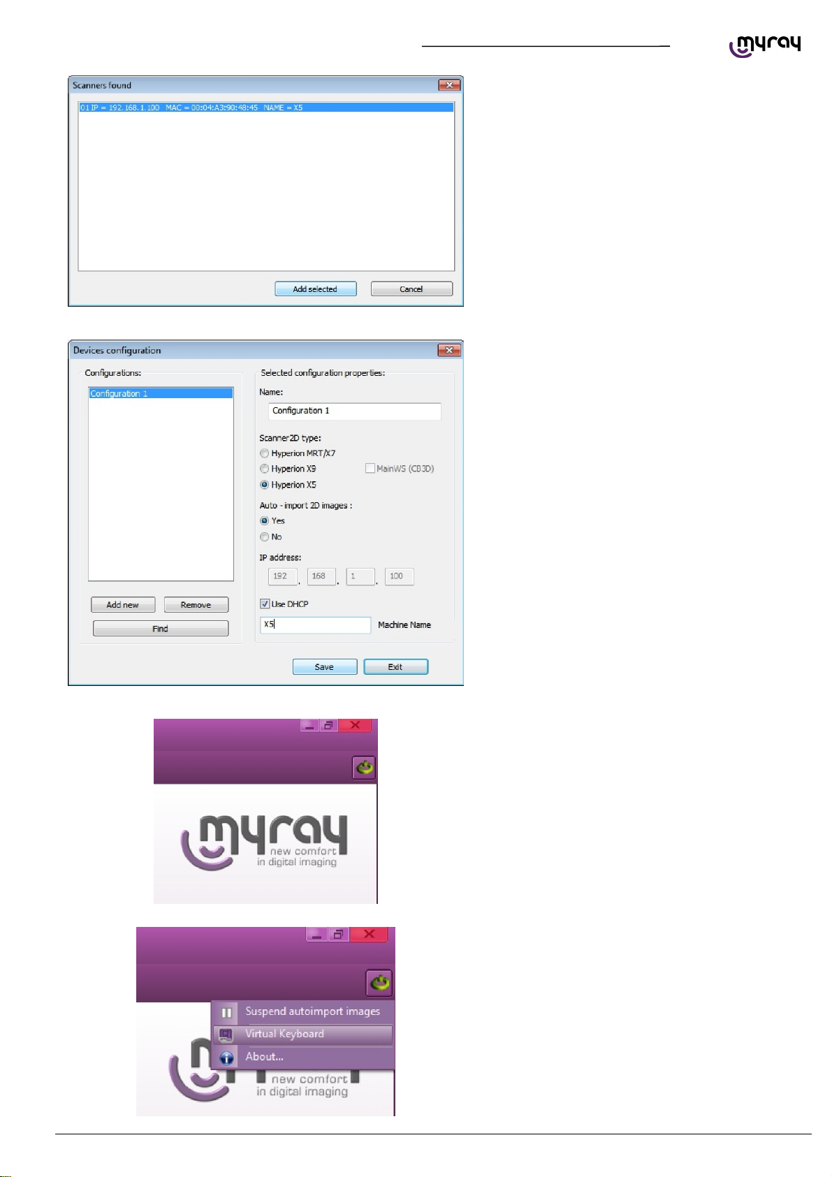
TECHNICAL MANUAL - hyperion X5
Configure the remote connection as shown in the
image here below. Click “Save” and then “Exit”.
The .hyperion X5 connection status icon will
appear in the upper right corner of iRys' interface.
Click on the icon and select “Virtual keyboard”:
EN
PC CONFIGURATION
25
Page 28
TECHNICAL MANUAL - hyperion X5
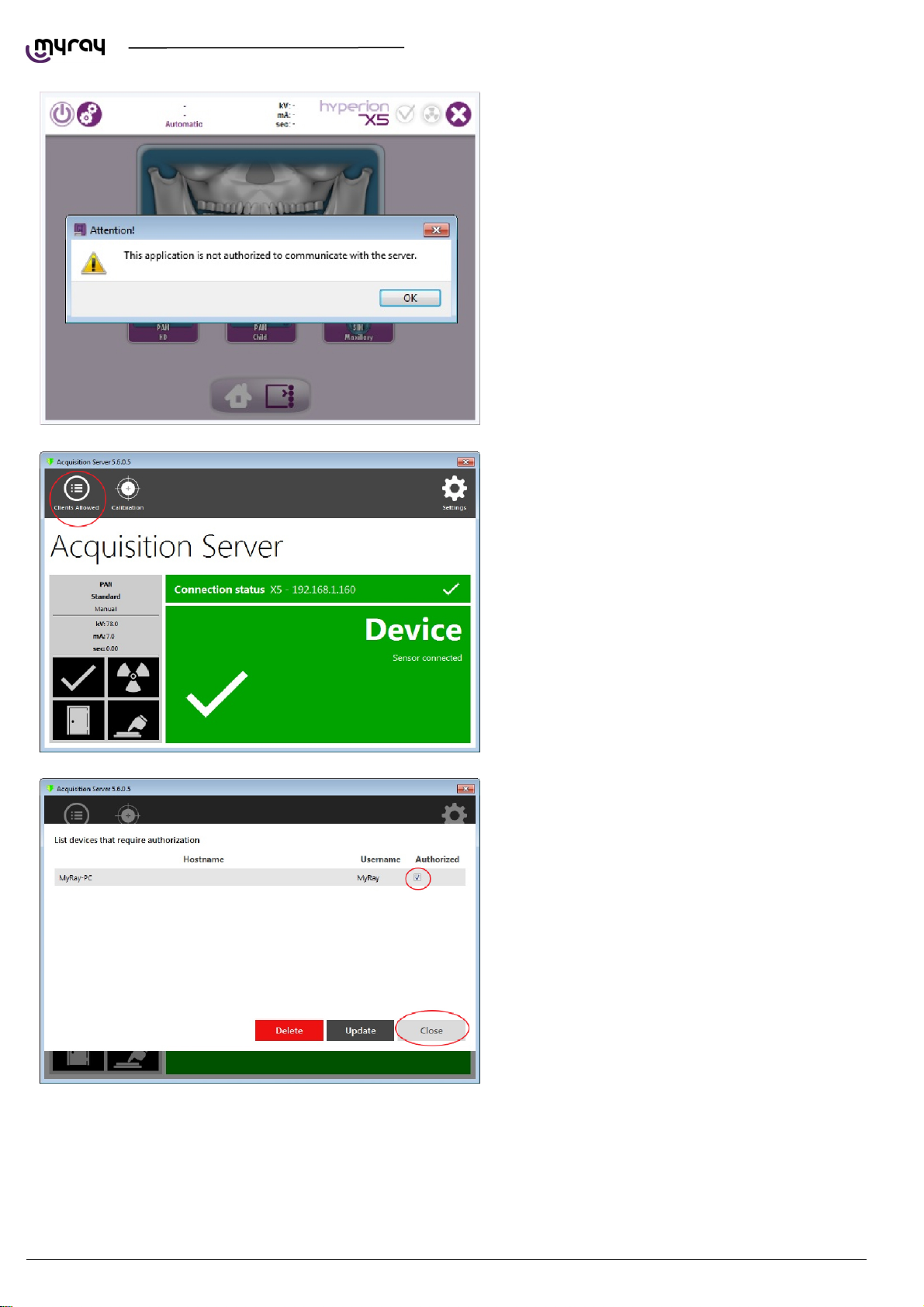
On first startup the console will prompt with this
message:
In order to authorize the virtual keyboard to
connect to the unit, you need to enter the
“Acquisition server” software and select “Clients
allowed”:
The clients list will appear, select the appropriate
one and close the window.
26
PC CONFIGURATION EN
Page 29
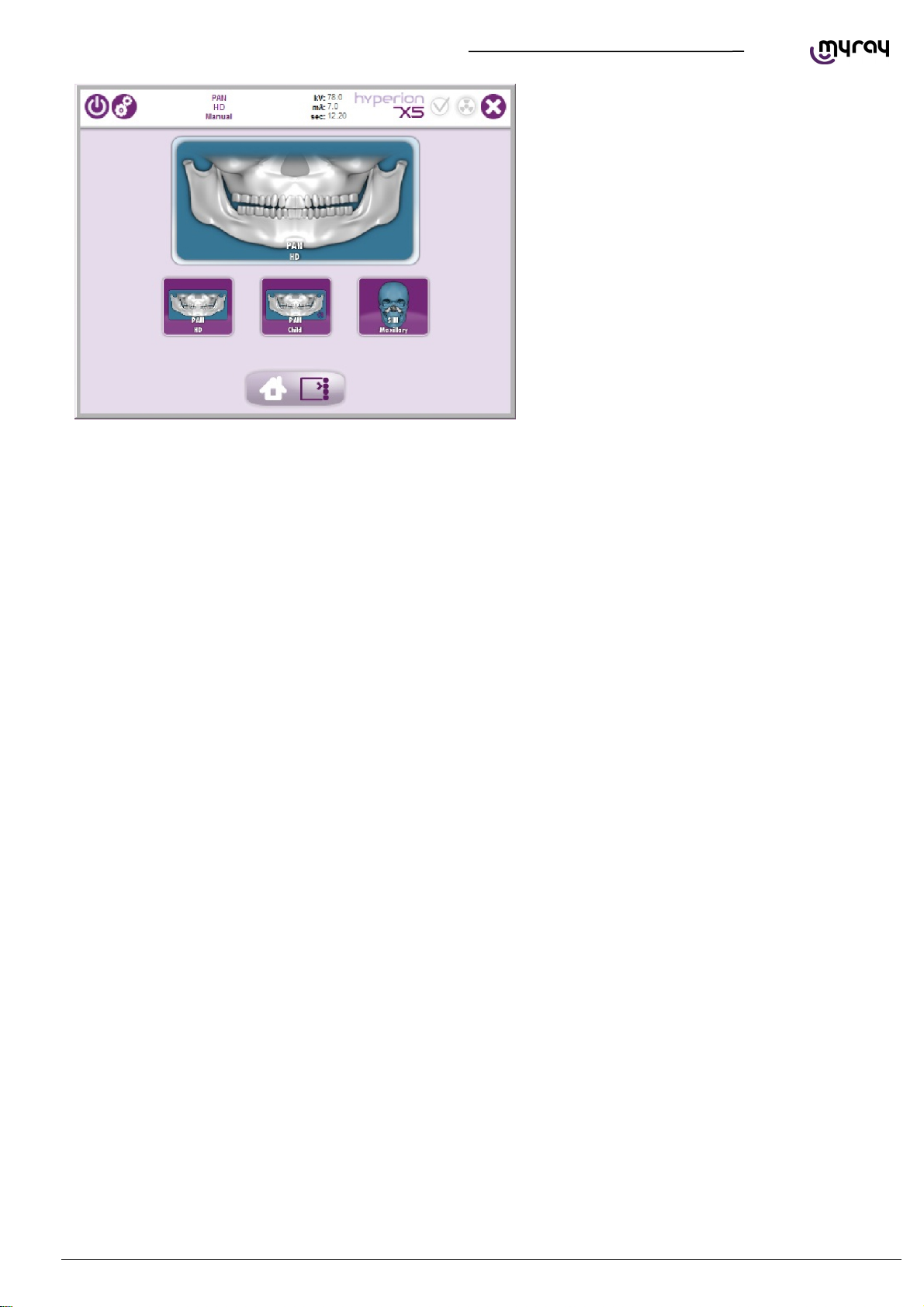
TECHNICAL MANUAL - hyperion X5
Now the .hyperion X5 virtual keyboard will connect
correctly:
EN
PC CONFIGURATION
27
Page 30
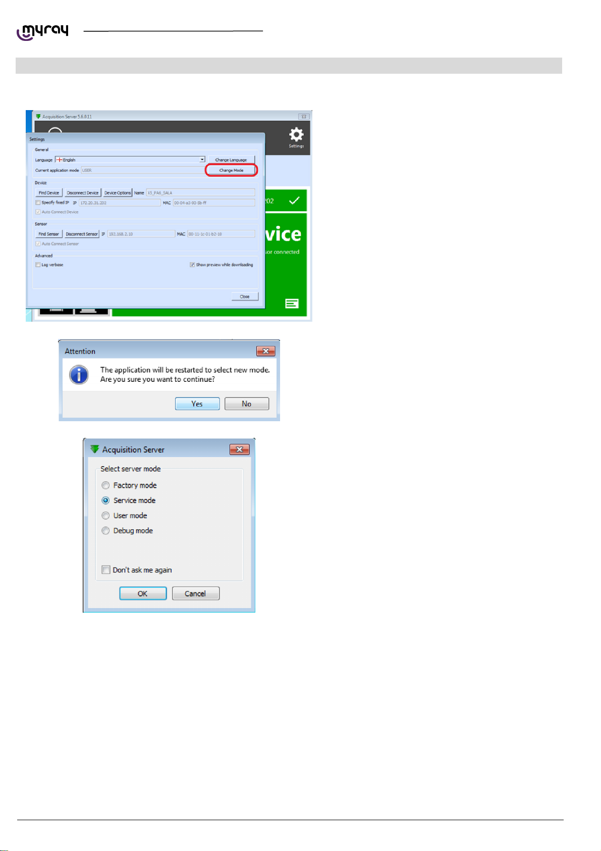
2.1. PRELIMINARY OPERATIONS
TECHNICAL MANUAL - hyperion X5
2. CALIBRATION
Open the acquisition server software, click on
“Settings”, then on “Change Mode” and confirm
when prompted.
Select “Service mode” and enter the password
“cefla”.
28
CALIBRATION EN
Page 31
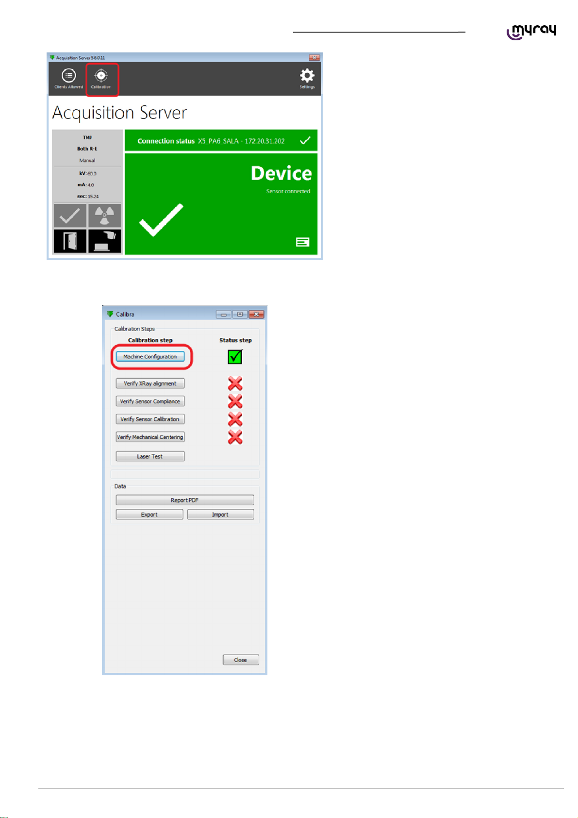
TECHNICAL MANUAL - hyperion X5
Open the Acquisistion server software and click on
“Calibration”.
2.2. DEVICE CONFIGURATION
EN
CALIBRATION
29
Page 32
A
TECHNICAL MANUAL - hyperion X5
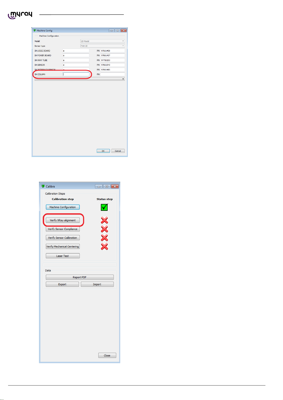
Enter the serial number of the column in the
textbox and presso “OK”
2.3. XRAY ALIGNMENT
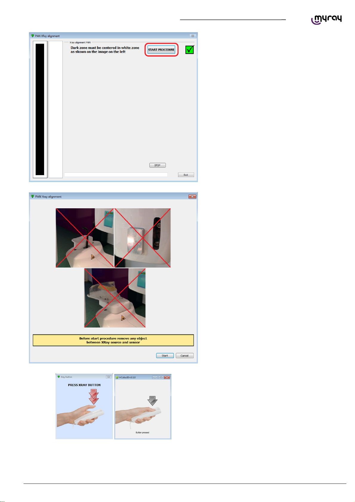
correct alignment should result in an image like
the example shown on the left side of the window
(dark rectangle with white background); click on
“Start procedure”.
30
CALIBRATION EN
Page 33
TECHNICAL MANUAL - hyperion X5
Make sure to remove every object from the scan
area (bite support, chin support, aluminum filter,
calibration phantom)
EN
Press the exposure button when required, hold
until asked to release.
CALIBRATION
31
Page 34
TECHNICAL MANUAL - hyperion X5
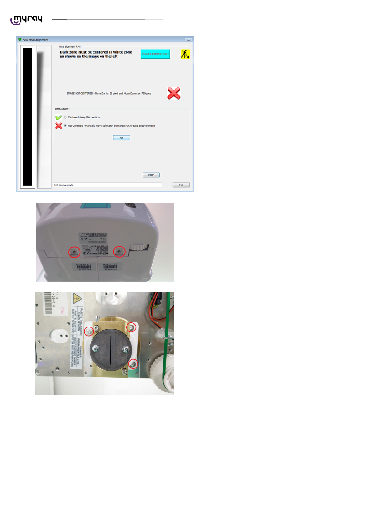
If the resulting image is not centered (like the one
in the following picture), the collimator needs to be
manually moved.
Remove the screws shown below to in order to
remove the front cover of the generator.
Centering the collimator horizontally or rotating it
Slightly loosen the screws shown in the following
picture, then move the collimator horizontally
and/or rotate the whole white plastic assembly if
required. Tighten the screw before taking the next
image.
32
CALIBRATION EN
Page 35
TECHNICAL MANUAL - hyperion X5
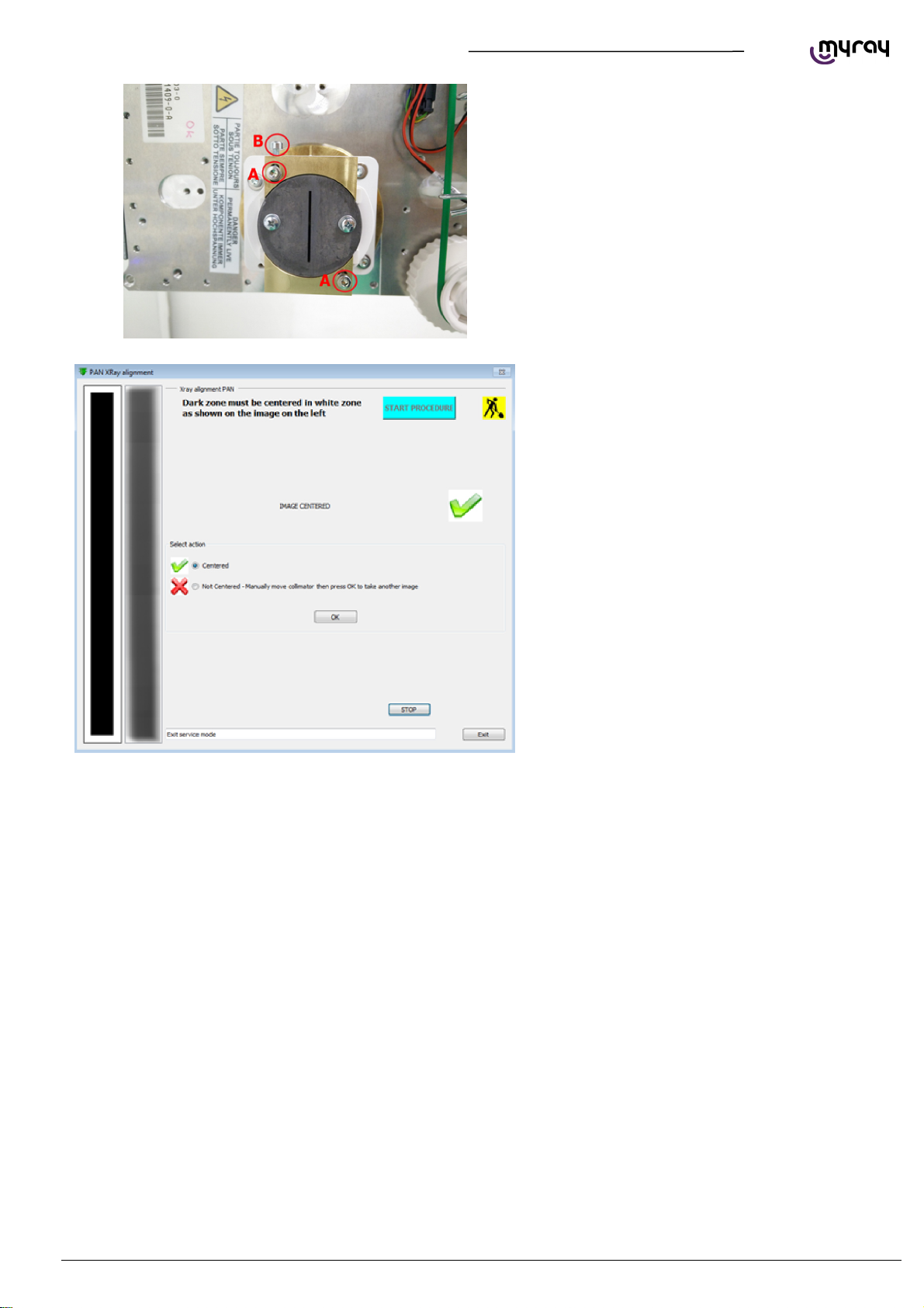
Select the “not centered” option in the calibration
tool, then presso “OK” to start a new acquisition in
order to verify the change made.
Repeat the procedure until the x-ray beam is
correctly aligned.
Centering the collimator vertically
Slightly loosen the “A” screws shown in the
following picture, loosen or tighten the “B” screw
to move the collimator up or down. Tighten the “A”
screws before taking the next image.
Select the “not centered” option in the calibration
tool, then presso “OK” to start a new acquisition in
order to verify the change made.
Repeat the procedure until the x-ray beam is
correctly centered.
When the x-ray beam is centered, select
“Centered” and click “OK”.
EN
CALIBRATION
33
Page 36
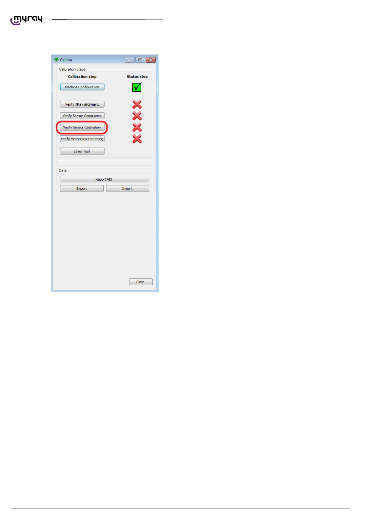
2.4. VERIFYING THE SENSOR CALIBRATION
TECHNICAL MANUAL - hyperion X5
Click on “Start procedure”, make sure to have
positioned the aluminum filter on the front cover of
the generator and to have removed every object
from the scan area (bite support, chin support,
calibration phantom)
The unit will automatically emit x-rays, performing
26 exposures. At the end of the procedure, perss
“OK” to complete this step.
34
CALIBRATION EN
Page 37
TECHNICAL MANUAL - hyperion X5
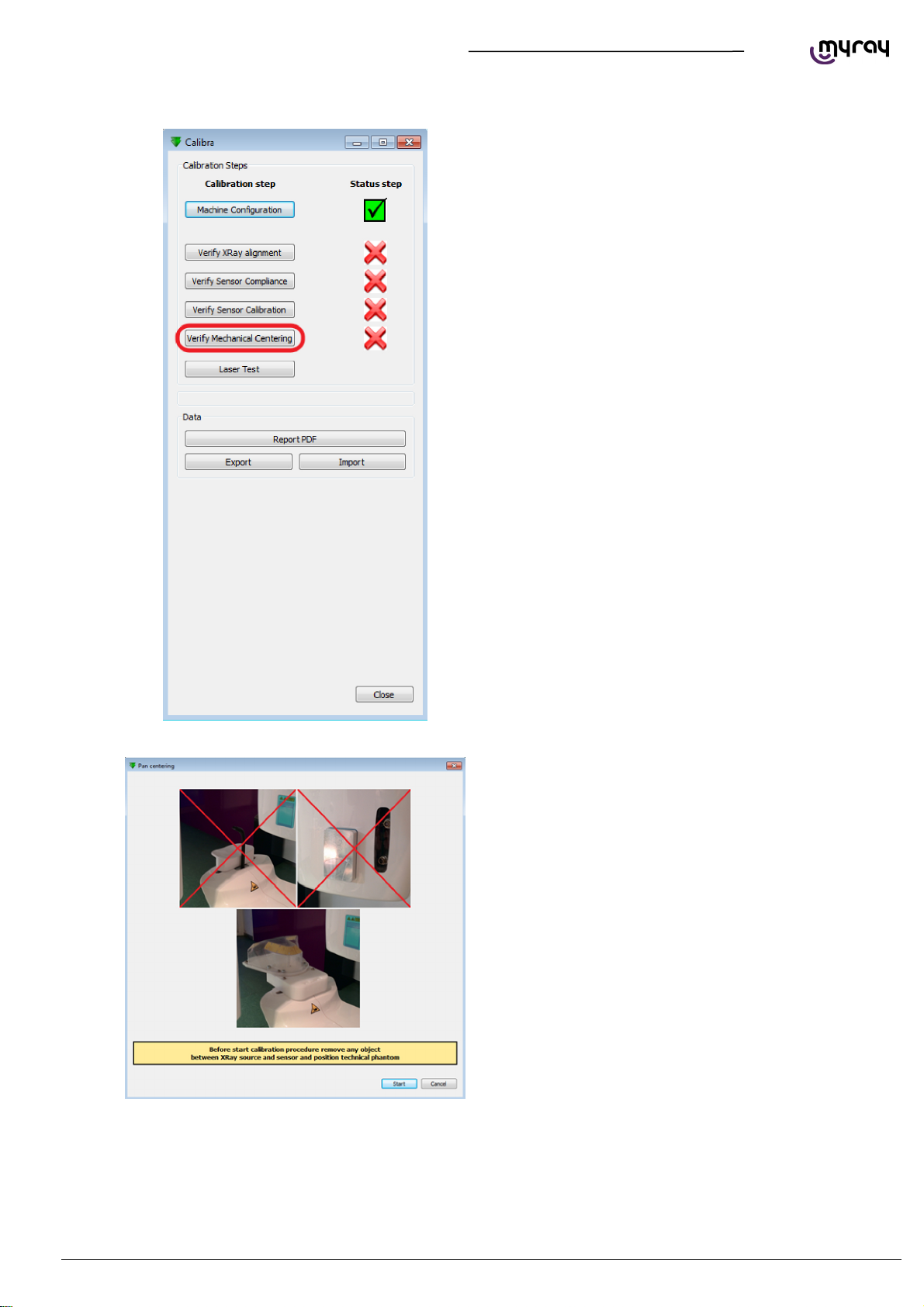
2.5. VERIFYING THE MECHANICAL CENTERING
Remove the bite support, chin support and
aluminum filter. Mount the calibration phantom
inserting the supporting pins into the holes
previously used for the chin support.
EN
CALIBRATION
35
Page 38
TECHNICAL MANUAL - hyperion X5
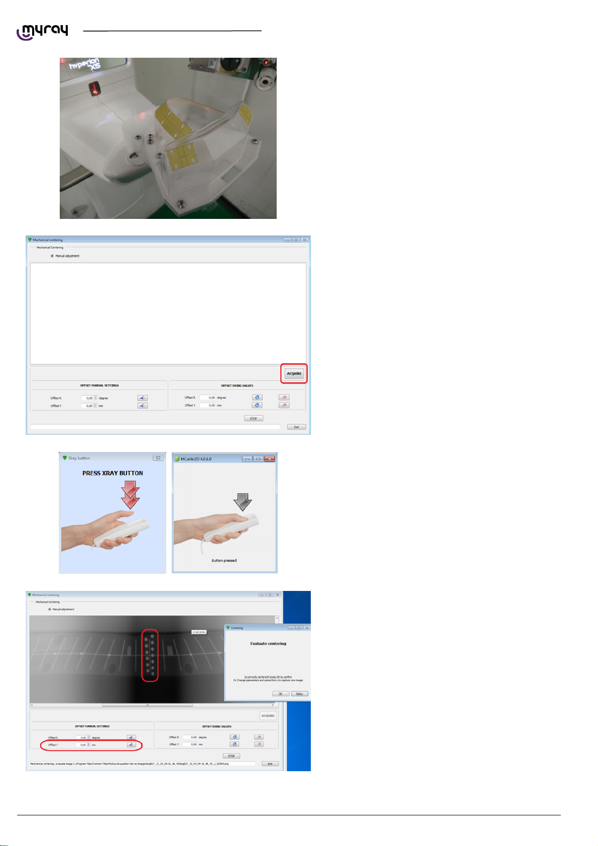
Click on “Acquire”.
Press the exposure button when required, hold
until asked to release.
36
The calibration software will download a complete
panoramic image and will show it on screen. You'll
need to verify that the focal area is centered. Use
the dots as reference. The numbero of blurred
dots above and below the central line should be
the same.
In case the focal area is not centered, modify the
“offset Y” value, click on the arrow and then on
“Retry”.
Click “OK” to confirm once the focal area is
centered.
CALIBRATION EN
Page 39
TECHNICAL MANUAL - hyperion X5
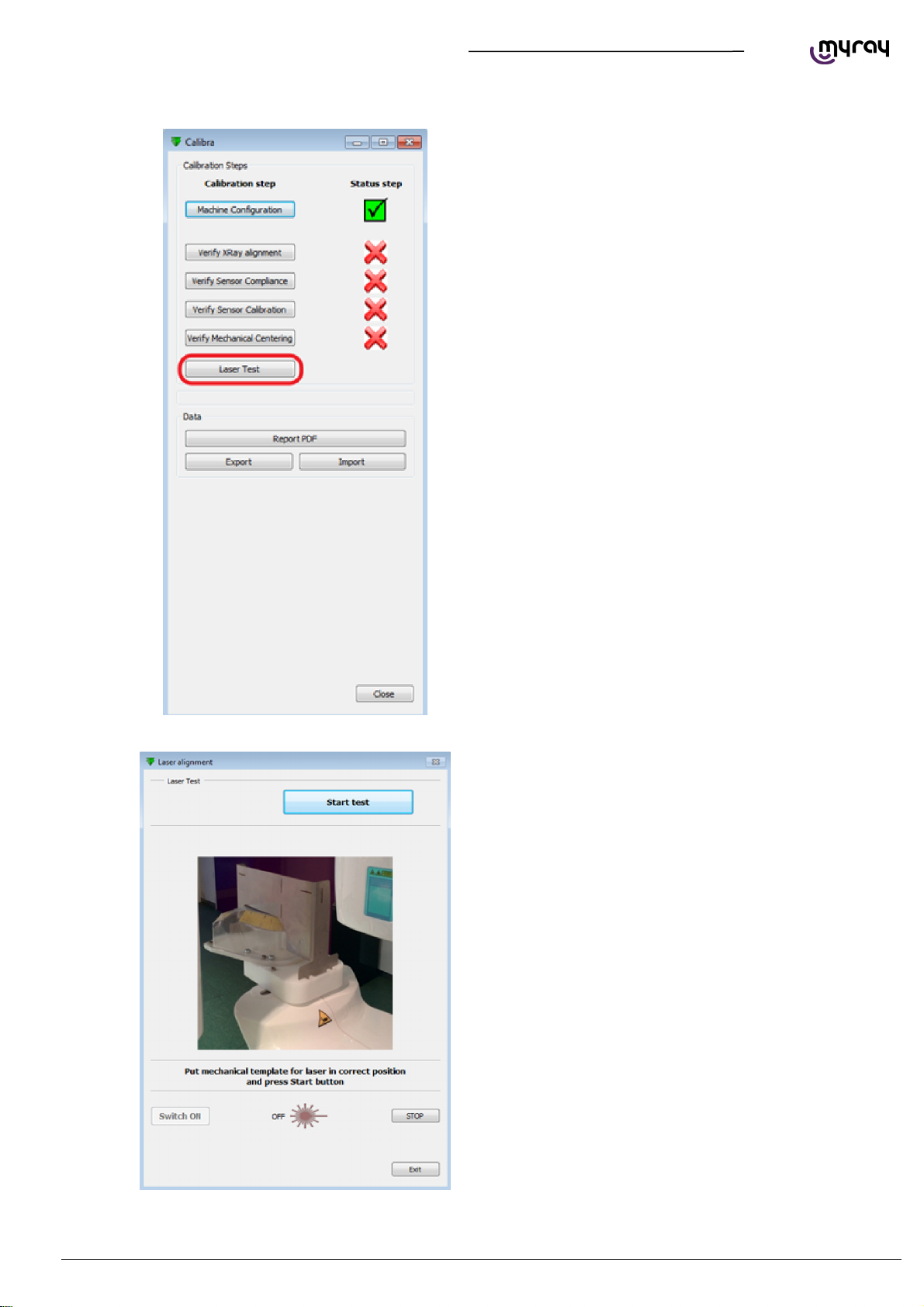
2.6. TEST LASER
Mount the laser guide tool on top of the calibration
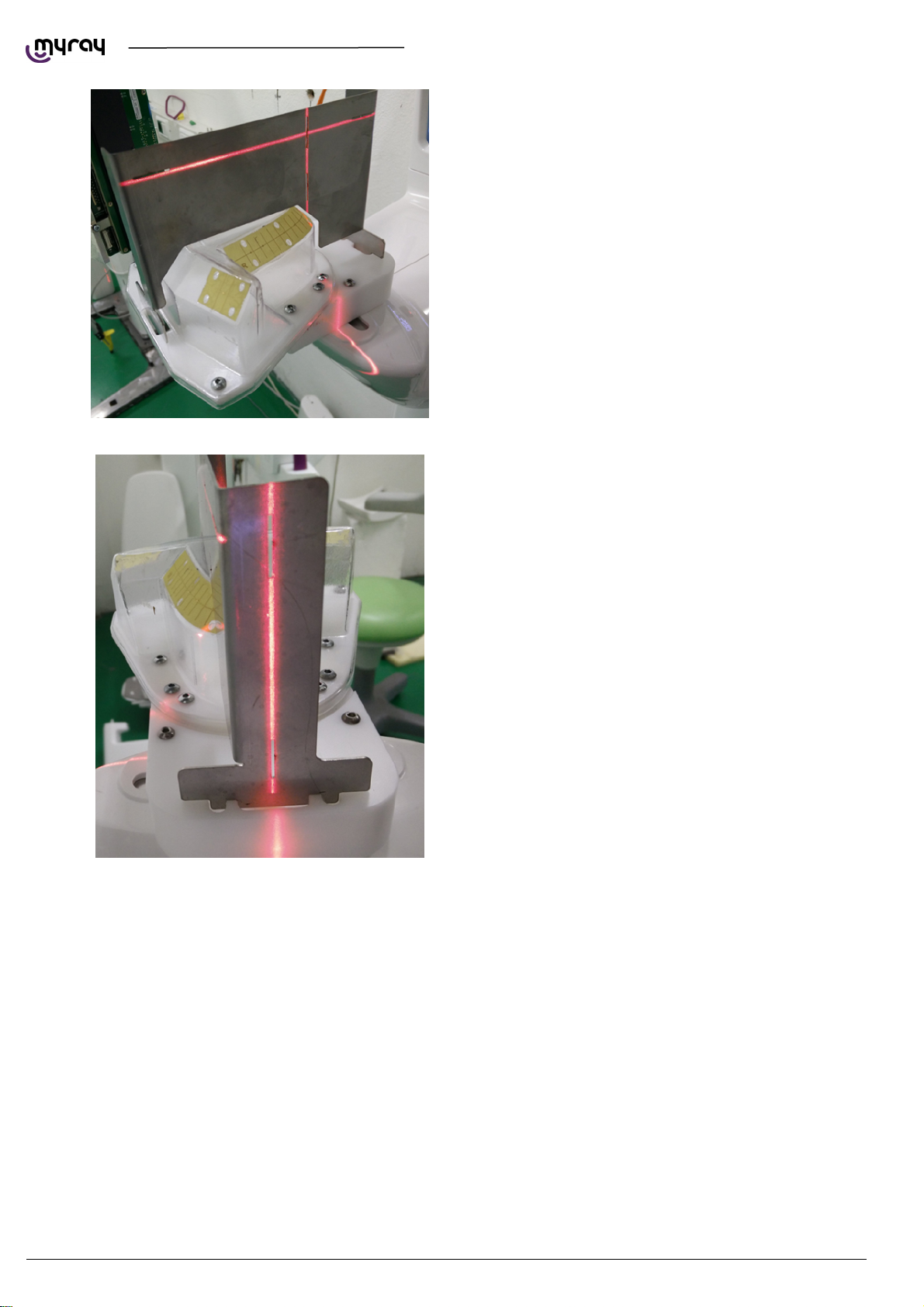
phantom (as shown below) and press “Start test”.
EN
CALIBRATION
37
Page 40
TECHNICAL MANUAL - hyperion X5
The unit will rotate into position for the laser test.
Check the alignment of the beams (sagittal,
canine, and frankfurt plane) with the reference
marks on the test object.
38
CALIBRATION EN
Page 41
TECHNICAL MANUAL - hyperion X5
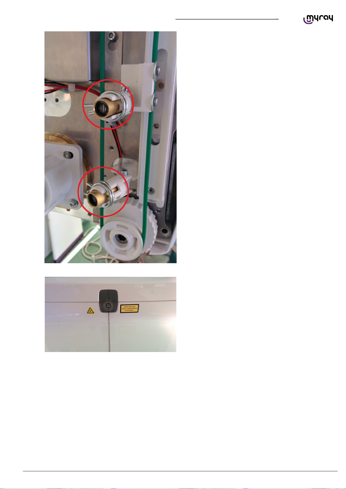
If one or more of the laser beams is not aligned,
use pliers to loosen the spring around the
projector support and align the beam manually.
The frankfurt plane and canine lasers are under
the generator cover.
Press “Exit ” at the end of the procedure.
The sagittal laser is below the mirror.
EN
CALIBRATION
39
Page 42
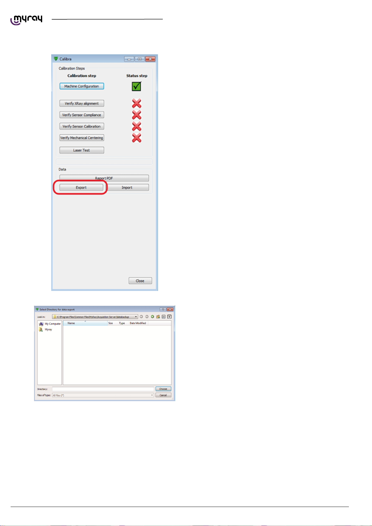
2.7. CALIBRATION DATA BACKUP
TECHNICAL MANUAL - hyperion X5
Click on “Export”, select the destination folder and
confirm.
40
CALIBRATION EN
Page 43
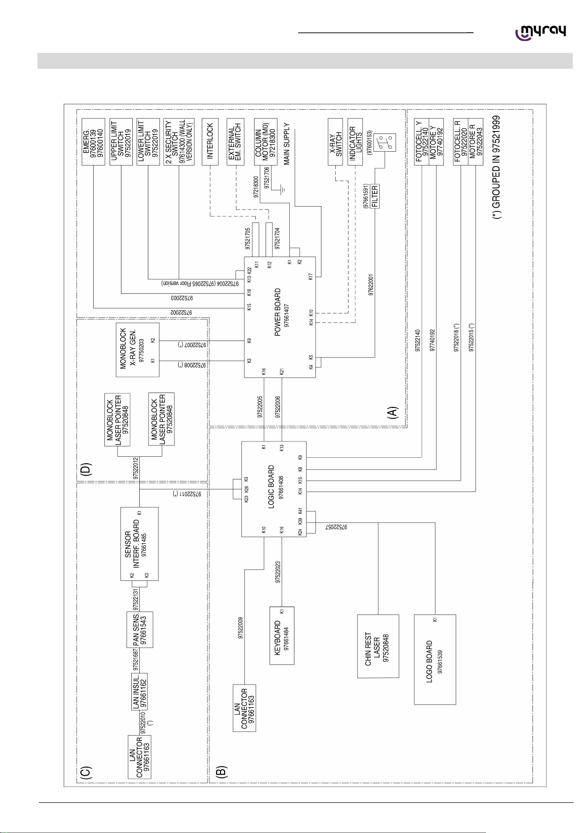
TECHNICAL MANUAL - hyperion X5
3.1. UNIT BLOCK DIAGRAM
3. CONTROL BOARDS DESCRIPTION
EN
CONTROL BOARDS DESCRIPTION
41
Page 44
3.2. POWER BOARD 97661407
TECHNICAL MANUAL - hyperion X5
42
CONTROL BOARDS DESCRIPTION EN
Page 45
TECHNICAL MANUAL - hyperion X5
EN
CONTROL BOARDS DESCRIPTION
43
Page 46
TECHNICAL MANUAL - hyperion X5
3.2.1. CONNECTORS LIST
CONNECTOR DESCRIPTION
K17 Mains power supply
K4 Power switch live wire
K5 Power switch neutral wire
K12 External emergency button - optional
K11 Door interlock - optional
K10 X-ray button
K14 External signal lamps – Optional- Wires 1,2 ready - Wires 3,4 x-ray emission
K16 Power supply for “logic” board
J3 Not used
K21 Can bus connector
K15 Integrated emergency button (on column)
K9 Monobloc feedback
K18 Column lower endpoint photocell
K13 Column upper endpoint photocell
K22 Column anti-pinch switch
K2 Column motor thermal sensor
K1 Column motor power supply
K3 Monobloc power supply
3.2.2. FUSES AND DIP SWITCHES LIST
FUSE ID NOTES DESCRIPTION
FH1/FH2 Mains power supply fuse
FUSE 20AF250v 6.3x32 115V
FUSE 12AF 250v 6.3x32 230V
F2 Standby power fuse FUSE 2AT 230V
F1 48V output fuse FUSE 2,5AF 450V DC
DIP Switches
SW1 Always off, reserved use
3.2.3. LEDS LIST
LED ID COLOR NAME ON BOARD DESCRIPTION
DL1 YELLOW ACT
DL2 RED ERR
DL3 GREEN CPU
DL4 YELLOW UP
DL5 YELLOW DN
DL6 RED STOP
DL8 YELLOW VAC
44
CONTROL BOARDS DESCRIPTION EN
CAN communication activity: normally flashing. Problems on CAN bus If off or
on steady
Error status, normally off. Flashing upon startup, the number of flashes
represents the FW version. When ERR is on the number of flashes from CPU
LED represents the error code.
Normally flashing at 1Hz
10Hz during column movement or x-ray emission
When ERR is on the number of flashes from CPU LED represents the error
code.
Normally off, if on the upper column endpoint has been reached. Always on if
photocell damaged or disconnected.
Normally off, if on the upper column endpoint has been reached. Always on if
photocell damaged or disconnected.
Normally off, if on the anti-pich microswitch has been pushed. Always on if
microswitch damaged or disconnected.
On when mains power supply is on.
Off during stand by or in case of issues with power amplifier on the board.
Page 47

TECHNICAL MANUAL - hyperion X5
LED ID COLOR NAME ON BOARD DESCRIPTION
DL9 YELLOW VDC
DL10 GREEN -5VA Analog -5.3V present, normally on
DL11 GREEN +5VA Analog +5.3V present, normally on
DL13 GREEN 18V 18V driver tension present, normally on
DL14 GREEN 12V 12V driver tension present, normally on
DL15 GREEN 5.0V 5V CPU tension present, normally on
DL16 GREEN 12V_EXT 12V for x-ray button, emergency button and interlock, normally on.
DL17 GREEN 3.3V 3.3V CPU tension present, normally on
DL18 GREEN 24V 24V tension present, normally on
DL19 GREEN SYNC Power-LOGIC boards sync signal, normally off
DL20 GREEN ENB
DL21 GREEN ACK Acknowledged signal from LOGIC board, normally off.
DL23 GREEN RDYL External “ready” lamp relay status. Normally off, on when unit is “ready”.
DL24 YELLOW XRYL External “x-ray on” lamp relay status. Normally off, on during x-ray emission.
DL25 GREEN BUT Xray button pressed. On when x-ray button is pressed.
DL26 YELLOW ILK Interlock status. Normally off. On if door is open or interlock is not connected.
DL27 RED EMG
DL28 YELLOW FIL
On when 390V are present on power amplifier.
Off when in stand-by or in case of issues with the power amplifier.
Inverter enabled signal from LOGIC board, normally on. Off during standby or
in error condition.
External emergency button status. Normally off. On if External emergency
button status is pressed or not connected.
X-ray filament on. On during emission.
DL29 YELLOW INV Inverter on. On during emission
DL30 YELLOW DRV Driver enabled, normally on. Off during standby or in error condition.
DL31 GREEN 48V 48V tension ON. Off during standby or in error condition.
DL32 YELLOW ON
Mains power supply to power ampifier relay status. Off during standby or in
error condition.
DL33 YELLOW PC Preload resistance by-pass relay. Off during standby or in error condition.
DL35 RED EMG
DL36 RED MT
Integrated emergency button status. Normally off. On if integrated
emergency button status is pressed or not connected.
Column engine overload. Normally off. On when thermal sensor is active or
not connected.
To connect the X-ray button, use k10 connector as follows:
PIN 1-2: X-ray emission contact
PIN 3: signal "Ready"
PIN 4: signal "X-ray ON"
PIN 5-6: not used
EN
CONTROL BOARDS DESCRIPTION
45
Page 48
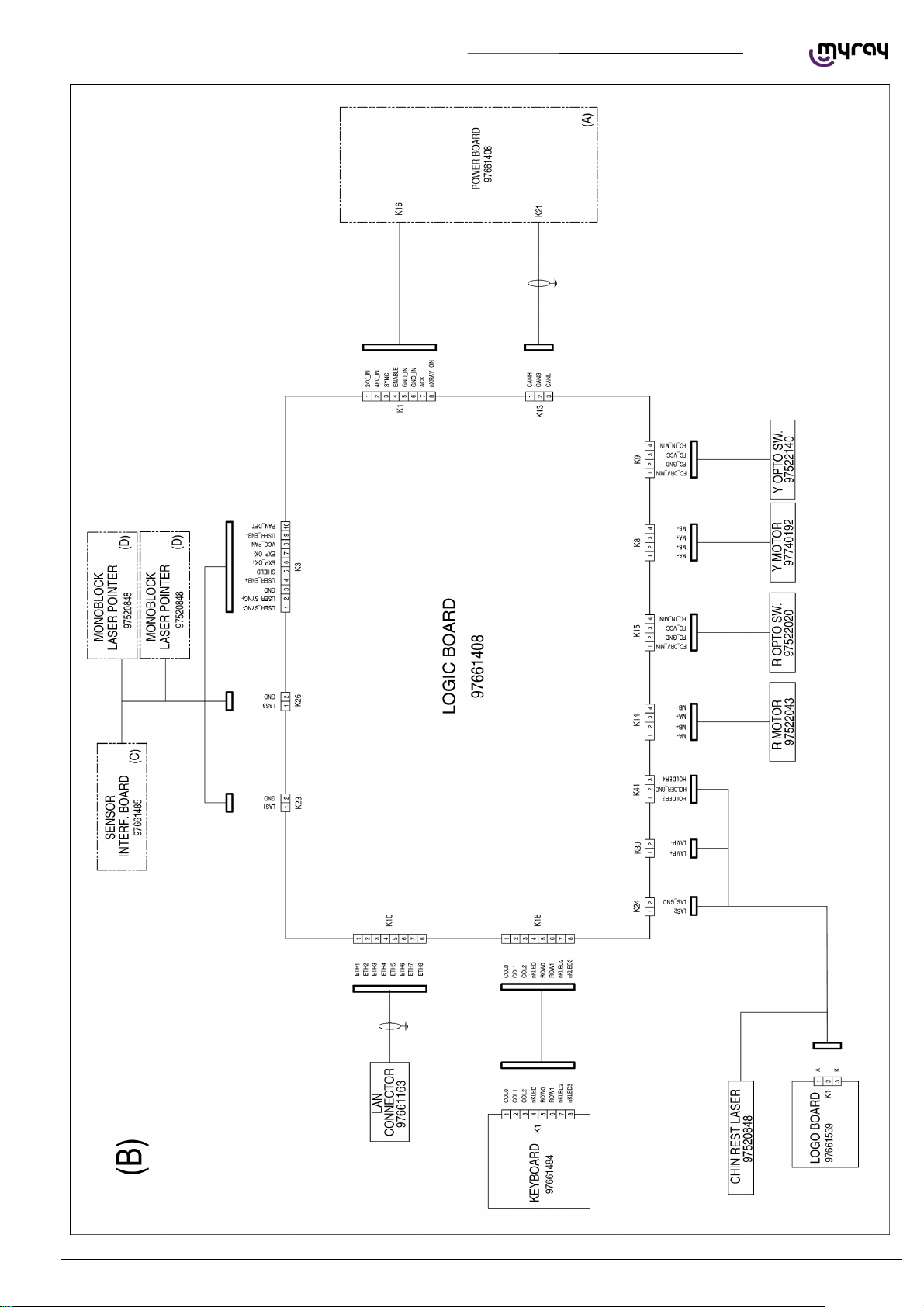
3.3. LOGIC BOARD 97661408
TECHNICAL MANUAL - hyperion X5
46
CONTROL BOARDS DESCRIPTION EN
Page 49
TECHNICAL MANUAL - hyperion X5
EN
CONTROL BOARDS DESCRIPTION
47
Page 50
TECHNICAL MANUAL - hyperion X5
3.3.1. CONNECTORS LIST
CONNECTOR DESCRIPTION
K10 Ethernet connection to PC
K3 Powe supply and sync signal for sensor interface card.
K41 Not used
K1 Power supply input from powe board
K39 24V power supply toward engraved logo light
K26 K23 Monobloc lasers
K24 Chin rest lasers
K2 Not used
K8 Y axis motor
K14 R axis motor
K5 Not used
K9 Y axis photocell
K15 R axis photocell
K16 Keyboard signals connector
K13 CAN connector to power board
K4 Not used
K31 Serial port, not used
K29 Not used
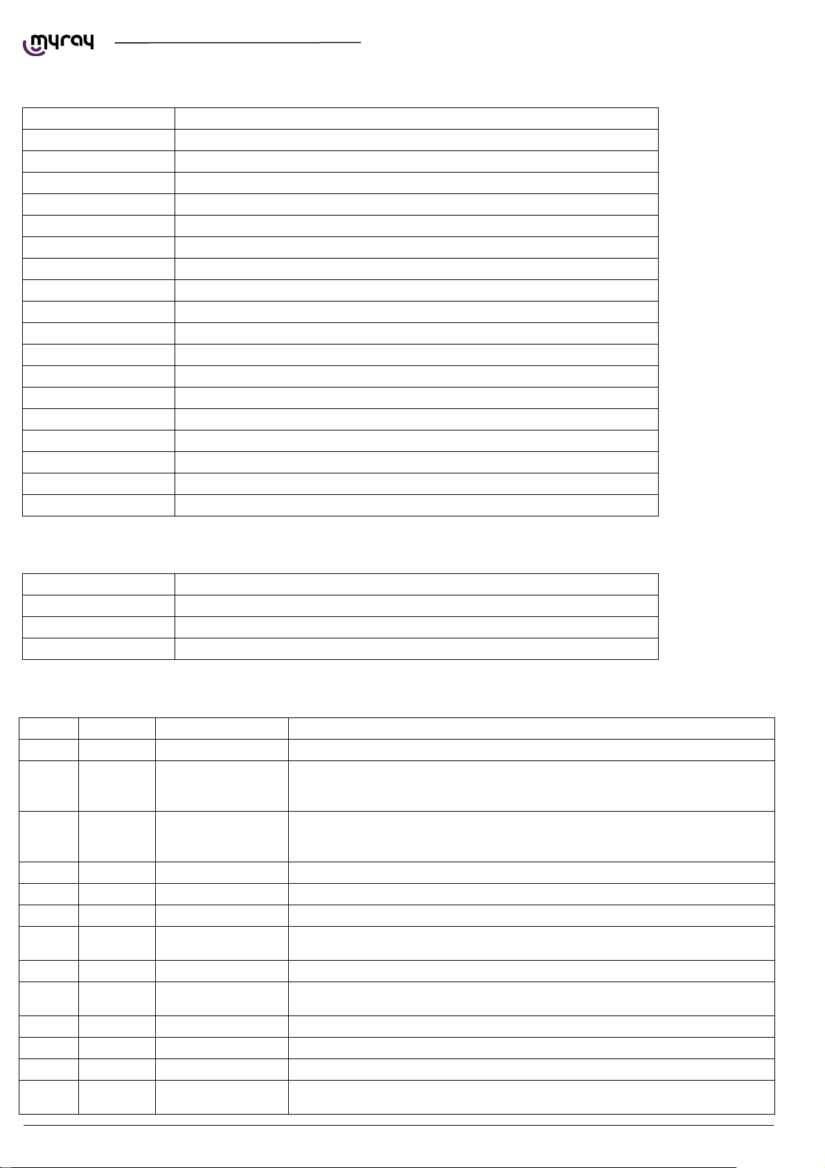
3.3.2. DIP SWITCHES LIST
DIP Switches DESCRIPTION
SW4 Not used, all OFF
SW2 Reboot button
SW3 Factory reset switch
3.3.3. LEDS LIST
LED ID COLOR NAME ON BOARD DESCRIPTION
DL1 YELLOW CAN ACT CAN activity. Normally on flashing. On steady or off in case of CAN error condition.
Error status, normally off. Flashing upon startup, the number of flashes represents
DL2 RED ERR
DL3 GREEN CPU
DL4 GREEN MOTORS Motors enabled, normally on.
DL5 GREEN SYNC_PAN Logic-sensor sync signal, normally off
DL7 GREEN MOTX Not Used
DL8 GREEN MOTY
DL9 GREEN MOTC Not used
DL10 GREEN MOTR
DL11 GREEN PROG FPGA programmed, normally on
DL12 GREEN RUN FPGA on, normally flashing (3Hz)
DL13 GREEN SYNC POWER-LOGIC sync signal, normally off.
DL14 GREEN ENABLE
the FW version. When ERR is on the number of flashes from CPU LED represents
the error code.
Normally flashing at 1Hz
10Hz during column movement or x-ray emission
When ERR is on the number of flashes from CPU LED represents the error code.
On if Y motor is active. If flashing the motor is in error (disconnected, short-circuit,
overheating, broken driver)
On if R motor is active. If flashing the motor is in error (disconnected, short-circuit,
overheating, broken driver)
Inverter enabled signal from LOGIC board, normally on. Off during standby or in
error condition.
48
CONTROL BOARDS DESCRIPTION EN
Page 51

TECHNICAL MANUAL - hyperion X5
LED ID COLOR NAME ON BOARD DESCRIPTION
DL15 GREEN ACK Acknowledged signal from LOGIC board, always on.
DL16 GREEN XRAY X-ray emission signal from Power board. Normally off, on during emission.
DL17 GREEN SD_ON Not used.
DL18 YELLOW ACT LAN activity LED. Normally flashing.
DL19 GREEN LINK LAN connection estabilished. Normally on.
DL22 GREEN 3.3V 3.3V CPU tension present, normally on
DL23 GREEN 24V 24V tension present, normally on
DL24 GREEN 5.0V 5V CPU tension present, normally on
DL25 GREEN 1.2V 1.2V CPU tension present, normally on
DL32 GREEN 48V R axis Motor tension present, normally on
DL33 GREEN FCR R axis photocell. On if photocell is obscured or disconnected/broken.
DL35 GREEN Not used
DL36 GREEN FCX Not used
DL38 GREEN 48V Y axis Motor tension present, normally on
DL39 GREEN FCY Y axis photocell. On if photocell is obscured or disconnected/broken.
DL42 GREEN EXP_OK_PAN
DL43 GREEN PAN_IN
DL46 GREEN PAN_ON
Exposure OK signal from sensor, normally off.
Sensor present, normally off. On if broken cable or sensor interface board is
disconnected.
48V Sensor power supply ok. Normally on.
Off during standby or in error condition on sensor or interface board.
DL49 GREEN 48V 48V from power board on. Off during standby or in error condition.
DL51 GREEN ENB_PAN
48V enabled on sensor. Normally on.
Off during standby or in error condition on sensor or interface board.
DL53 GREEN CHIN_L Not used
DL54 GREEN CHIN_R Not used
EN
CONTROL BOARDS DESCRIPTION
49
Page 52
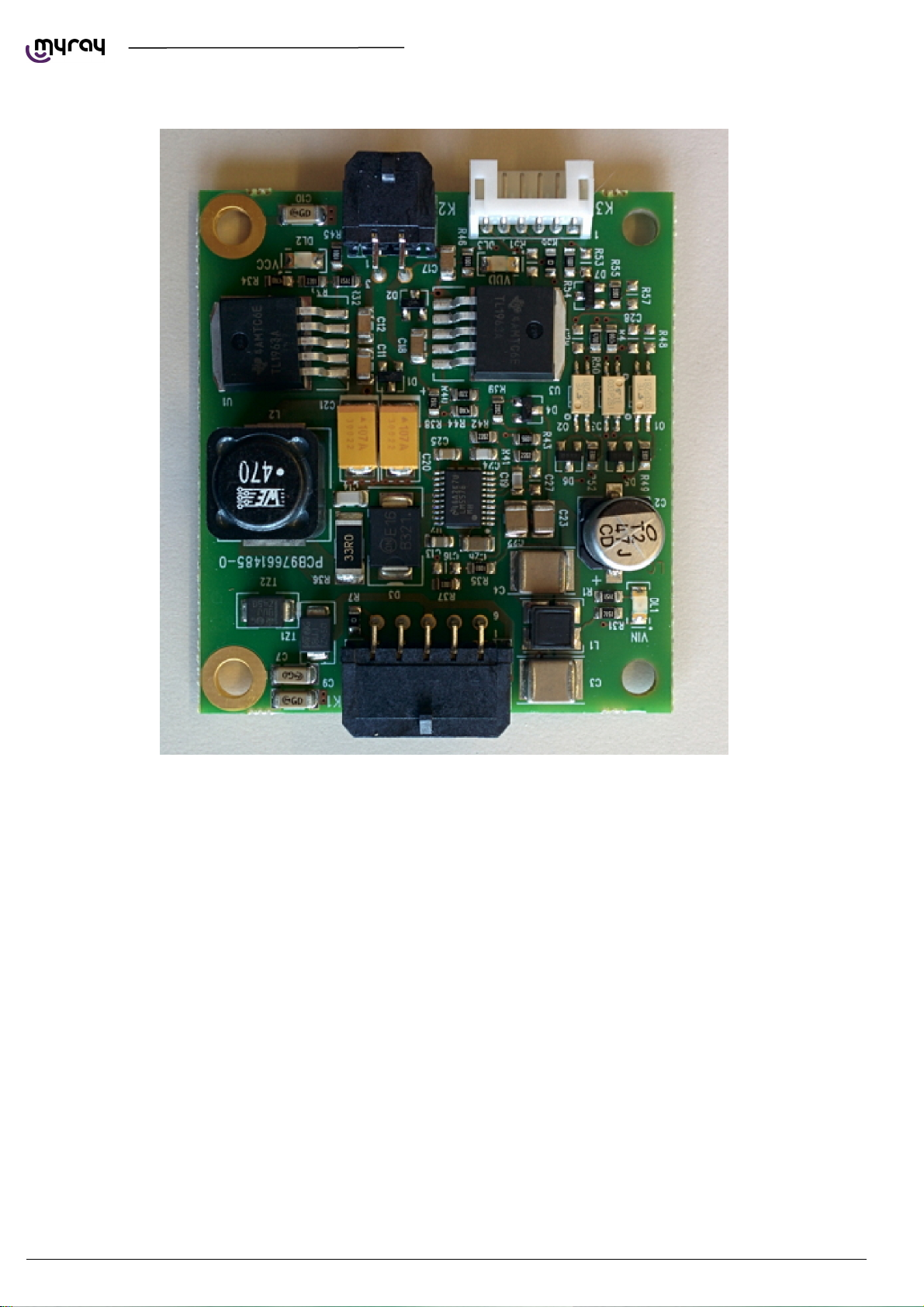
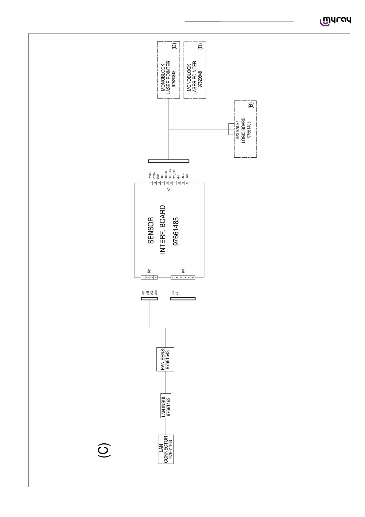
3.4. SENSOR INTERFACE BOARD 97661485
TECHNICAL MANUAL - hyperion X5
50
CONTROL BOARDS DESCRIPTION EN
Page 53
TECHNICAL MANUAL - hyperion X5
EN
CONTROL BOARDS DESCRIPTION
51
Page 54
A
3.4.1. CONNECTORS LIST
CONNECTOR DESCRIPTION
K1 Sync signal and power supply for sensor, from LOGIC board.
K2 Sensor power supply, 2x 5V DC
K3 Sensor synchronization
3.4.2. LEDS LIST
LED ID DESCRIPTION
DL1 (VIN) 48V from LOGIC board
DL2 (VCC)
nalog 5V towards sensor
DL3 (VDD) Digital 5V towards sensor
3.5. KEYBOARD BOARD 97661484
3.5.1. CONNECTORS LIST
CONNECTOR DESCRIPTION
K1 Keyboard signals from LOGIC
3.6. LOGO BOARD 97661539
TECHNICAL MANUAL - hyperion X5
3.6.1. CONNECTORS LIST
CONNECTOR DESCRIPTION
K1 24V power supply fron Logic board
52
CONTROL BOARDS DESCRIPTION EN
 Loading...