

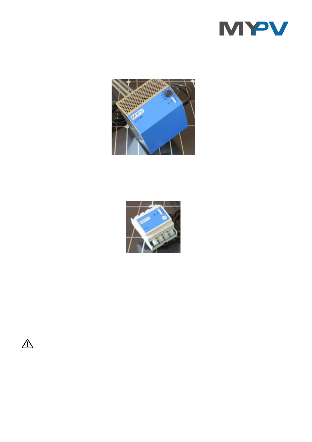
AC ELWA
®
PV Excess-Energy Hot Water System
PLA
3-phase Meter/Controller
Installation and Operating Instructions
Intended Use
The electrical device PV excess-energy hot water system AC ELWA (referred to as AC ELWA) is intended for
stationary installation in hot water storage or buffer tank storage. The device is controlled by external control
signals and adjusts its heating power from zero to 3000 W accordingly.
You can use the AC ELWA also with Universal Interface!
The PLA Meter/Controller is incorporated in the power distribution immediately after utility meter fuses. It is
suitable for single-phase and three-phase systems. The neutral conductor shall be connected in any case.
Any other use than described above may damage the device, moreover, this involves dangers such as short
circuit, fire, electric shock, etc. The safety instructions and the information on handling in this manual and in
the application instructions shall be followed!
The product complies with the applicable National and European requirements. Company and product name
are trademarks of my PV GmbH. All rights reserved.

2
Delivery
• Electric photovoltaic excess-energy hot water system AC ELWA
• Connection plug for control cable connection between AC ELWA and PLA Meter/Controller
• IP21 cover
• Operating instructions
safety instructions
The installation must be carried out exclusively by the authorized expert.
When installing and connecting the relevant standards must be observed.
Warranty does not cover any damages caused by failure from disregarding these operating instructions.
A permanent earthing of the hot water tank is mandatory.
Never switch the unit on when the heating element is not surrounded and cooled by water.
The housing must not get damp or wet, it is only suitable for dry indoor areas. Danger of fatal electric shock!
Do not install device in ammonia-contaminated environments.
Do not install in dusty environment.
The ventilation holes of the housing don’t have to be closed.
Orientation of the device (horizontal heater, power cord below) must be maintained.
The PLA Meter/Controller must be mounted on a standard 35 mm DIN rail.
Avoid storage and operation temperatures > 40 ° C) and <5 ° C, do not expose to direct sunlight.
The AC ELWA must be connected to a nominal voltage of 230 VAC.
The circuit breaker of the grid connection for AC ELWA must be rated 13 A to 16 A, AC ELWA can be
adjusted accordingly.
The PLA Meter/Controller must be connected to 1 x 230 V AC or 3 x 230 VAC with Neutral. The allowed
fusing of the mains connection may be max. 65 A.
The safety thermostat responds to 98 +/- 3 ° C and the unit switches off permanently.
In commercial institutions, the accident prevention regulations of the professional associations must be
observed for electrical systems and equipment.
This unit can be used by children ages 8 and persons with reduced physical, sensory or mental capabilities
or lack of experience and knowledge if they have been given supervision or instruction concerning the safe
use of the equipment and understand the resulting risks. Children should not play with the appliance.
Cleaning and user maintenance shall not be undertaken by children without supervision.
Liability and warranty exclusion
A liability and warranty exclusion applies to:
any damage or injury caused by improper handling or failure to observe the safety and operating
consequential damages
Unauthorized remodeling, disassembly or other interventions in the device, modification of the
product
Damage caused by calcium deposits on heating element.
AC ELWA® Installation and Operating, Version 1.0, Date 2016-01-23 3
Installation of AC ELWA
The installation must be carried out exclusively by the authorized personnel.
The hot water storage tank must be drained properly before installing the AC ELWA.
AC ELWA is designed for horizontal installation in hot water tank with 1 ½ inch thread. The unheated zone of
the built-in heating element is 90 mm from sealing surface. The length of the mounting socket must not
exceed 90 mm. The pre-assembled O-ring seal has to be used; it must not be treated with lubricants. The
plastic thread must not be sealed with hemp or other sealants.
During mounting you have to screw without any effort until the seal rests lightly. Make sure that the O-ring is
clean in the groove of the plastic part. Tighten the heater with a spanner nominal width 60 mm. The
tightening torque must not exceed 80 Nm.
In no case the heater may be tightened by turning the metal case!
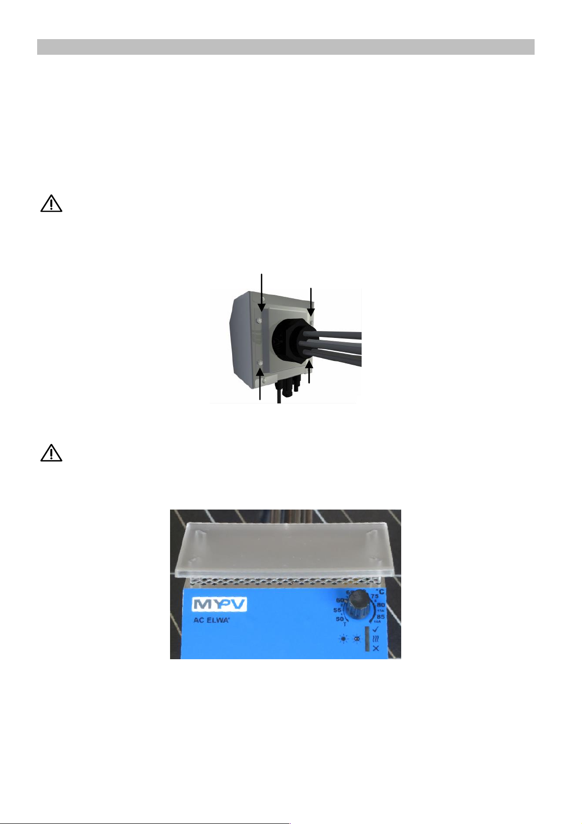
If the device does not stand up straight (power cord down) after tightening, it can easily be turned to the left
or right for about 180 °.
Then tighten the 4 lock nuts of the mounting plate of the heater to fix the unit in its straight position:
When refilling the water tank ensure that the heating elements are completely surrounded by water.
Subsequently, the tank must be checked for leakage.
After mounting the supplied IP21 cover is to be attached!
4
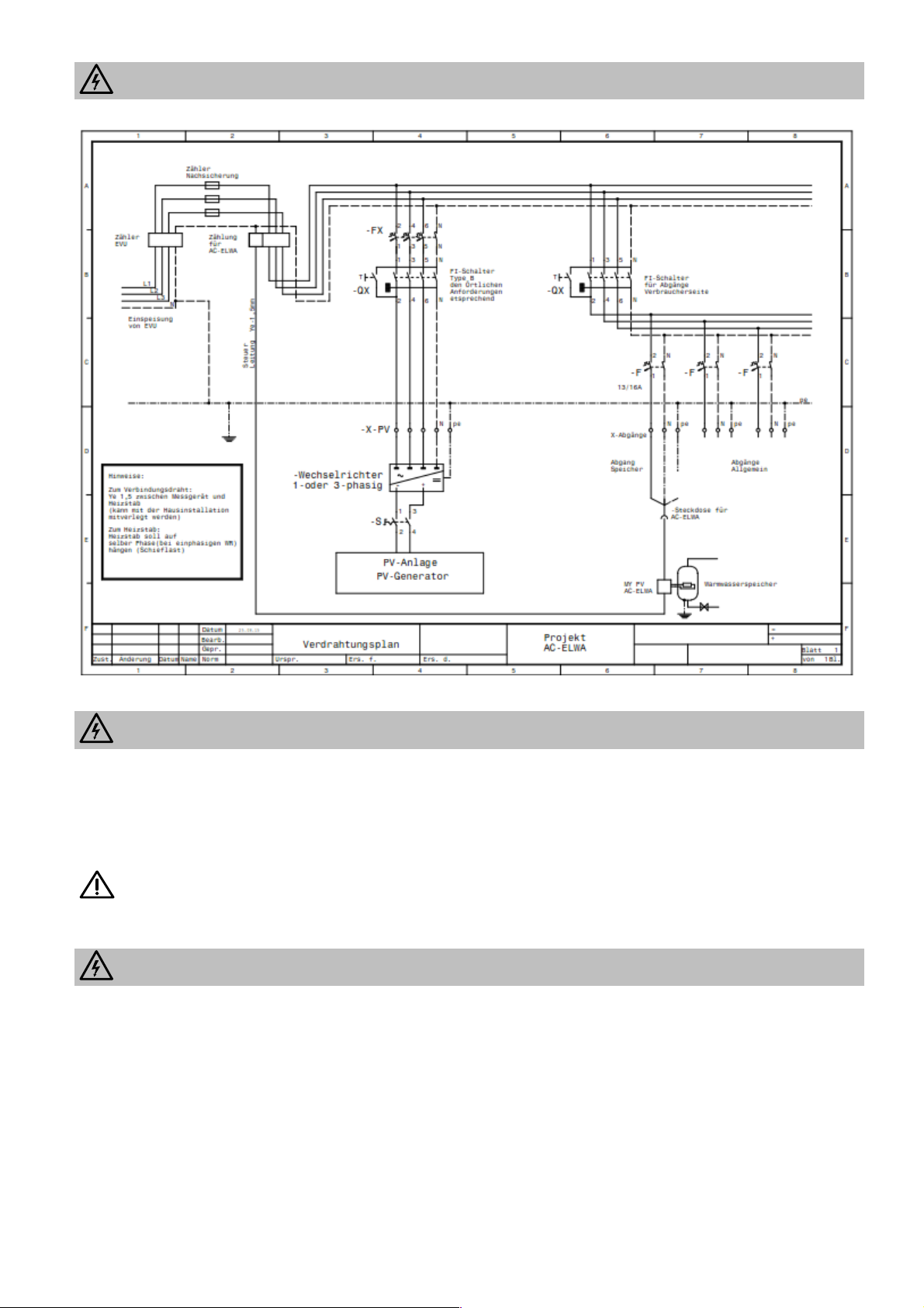
Electrical connection scheme
Electrical connection AC ELWA
To ensure proper operation of the control line to PLA (data modulation), the AC ELWA has to be connected
with the correct polarity at the socket.
The power plug is marked with "N". The "N" side of the plug must be connected to the "N" pole of the socket
(check with voltage meter).
AC ELWA has to be connected to a 13 or 16A circuit breaker socket.
The PE conductor of the socket must be present!
Pay attention to other loads on the line circuit, this may trip the circuit breaker!
Electrical connection PLA
Remove the fuses after the utility meter before connecting.
There are at least one phase (single – phase at utility meter) and the neutral conductor to connect.
Observe local regulations!

AC ELWA® Installation and Operating, Version 1.0, Date 2016-01-23 5
Control line between AC ELWA and PLA
The control cable between AC ELWA and PLA may be installed in AC wiring conduits. There is no separate
installation necessary (local regulations must be observed!)
The strain relief of the connector must be mounted. Exposed areas of the control line need double
insulation! The entry of the control line in the wall socket must comply with local regulations (strain relief).
The control cable for PLA is attached to the two-pin plug to the AC ELWA. (0,5 - 1,5 mm²). The poles (L and
N) on the connector are short-circuited inside the unit, so that a redirect to other AC ELWAs (up to 6) is
possible.
Installation of the plug:
The labels L and N on the connector have no meanings! Never connect the control wire with L or N of
the wall socket!
Connection of the control line at the PLA:
Electrical connection of several AC ELWAs in a system
All AC ELWAs (max. 6) should be connected to appropriate AC circuits.
Warning: any AC ELWA can take up to 3 kW!
It is recommended to divide the ELWAs on the 3 phases.
Note: More than 6 ELWAs can be controlled with the Universal Interface via RS485.

6
Controls and displays AC ELWA
Operating, display and connecting elements PLA
Indicators
Startup
Standby
Heating with excessenergy
Heating for hot water
ensuring (reheating)
Heating terminated
temperature reached
Setup Mode
No control signal
fault
Symbols
LED on
LED flashes
LED off
temperature adjustment knob
1-6 ... AC ELWA number in the operation of
multiple devices on a PLA
13A/ 16A …circuit protection
Green LED reaches desired temperature (flashes in
standby)
LED yellow: mains operation
LED red: no control signal or disturbance
Green LED reaches desired temperature (flashes in
standby)
LED yellow: heating
LED red: no control signal or disturbance
Configuration button
Load side: L1out L2out L3out data connection to PLA
L1in L2in L3in Nin (utility grid side)

AC ELWA® Installation and Operating, Version 1.0, Date 2016-01-23 7
Factory settings AC ELWA
AC ELWA number 1
16A fuse for the power outlet of the AC ELWA
automatic hot water ensuring disabled
Factory settings PLA
Reheating off
Stratification charge with more than one AC ELWA
Commissioning AC-ELWA - PLA
1. Activate the main switch of the house after you install the PLAs again.
2. Select the desired storage temperature at the knob of AC ELWA.
3. Insert the plug of the AC ELWA.
4. The connection between PLA and AC ELWA builds up independently.
5. At the PLA and the AC ELWA either flashes
green LED (standby, no excess) or
yellow LED lights (surplus is used).
As long as the red LED on the AC ELWA and PLA lights, no communication has been established.
Check control wire.
6. When the desired temperature is reached AC ELWA
LED lights green: Device switches off.
Set AC ELWA circuit protection (13A/ 16A)
The AC ELWA can produce up to 3,000 W (16 A). For 13 A fused circuits the power can be limited to 2,500
W.
Configure the device as follows
1. Disconnect power plug
2. Set the temperature knob to wrench icon. .
3. Insert power plug
all 3 LEDs flash (Setup mode is active)
4. Set temperature control knob to “13A”
LEDs run from top to bottom: green, yellow, red, green ... ..
5. Value is saved automatically if the control knob is left unchanged for 5 seconds
all three LEDs flash rapidly for 2 seconds, setting is saved.
6. Set temperature control knob to the desired temperature value.
The setting can be undone. Repeat same procedure as above, (adjusted to 16 A mark)
Set AC ELWA device number
The AC ELWA is factory configured to operate as a single device. If several units are operating in a system
together, the other AC ELWAs has to be configured as following:
1. Disconnect power plug
2. Turn temperature control knob to "wrench icon".Symbol
3. Insert power plug
all 3 LEDs flash (Setup mode is active)
4. Set temperature control knob to the desired number
Yellow LED flashes to indicate number (see table)

8
AC ELWA
number:
LED green
LED yellow
LED red
1
Flash
off
off
2
off
Flash
off
3
Flash
Flash
off
4
off
off
Flash
5
Flash
off
Flash
6
off
Flash
Flash
5. Value is saved automatically if the control knob is left unchanged for 5 seconds
all three LEDs flash rapidly for 2 seconds, setting is saved.
6. Set the temperature control knob to the desired temperature value.
The setting can be undone. Repeat same procedure as above.
Set AC ELWA the reheating (automatic hot water ensuring)
The AC ELWA can ensure hot water even with no excess energy. Initially, this function is disabled.
The device must be configured as follows:
1. Disconnect power plug
2. Turn temperature control knob to „wrench icon“
3. Connect the mains plug again
all 3 LEDs flash (Setup mode is active)
4. Set the temperature control knob to a ° C mark. The setting value corresponds to the temperature of
the table below:
LEDs red / green (simultaneously) and yellow alternately
Position control
knob:
Corresponds to reheat
temperature
55° C
off
60° C
40° C
65° C
45° C
70° C
50° C
75° C
55° C
80° C
60° C
85° C
65° C
5. Value is saved automatically if the control knob is left unchanged for 5 seconds
all three LEDs flash rapidly for 2 seconds, setting is saved.
6. Set the temperature control knob to the desired temperature value
The setting can be undone. Repeat same procedure as above. Reheating must be activated on PLA
additionally, because PLA controls all connected AC ELWA.

AC ELWA® Installation and Operating, Version 1.0, Date 2016-01-23 9
PLA Settings
1x: Setup mode 6x: Charge 6x: Charge1x: Setup mode
Normal mode Normal mode
Reheat on Stratification Synchron
Reheat off
2x: Setup time 2x: Setup time 2x: Setup time
0x: time0_: __ 1x: 1 time_:__ 2x: 2 time_:__
3x: Setup time 3x: Setup time
0x: 0 time1 :__ 9x: time1 :__9
4x: Setup time 4x: Setup time
short keystroke
1 s keystroke
1 s keystroke
5 s keystroke
LED on
LED flashes
5 s keystroke
0x: 00 time10: 3x: 45 time10:
1
1x: 15
2
2x: 30
3 4 5 6 7 8
The value for backup heating or stratification / synchronous charge is stored with 1 second keystroke
permanently. Menus are automatically exited without saving if key is not pressed for 30 seconds.
Reheating:
In the first menu item reheating can be enabled. This function is for automatic hot water ensuring. This allows
you to switch off the heating system used normally to heat water. Reheating is useful in non-heating period.
If reheating is on, all connected AC ELWAs which have an adjusted reheating temperature will be activated
from 16:00-23:00, regardless of whether or not excess power is available. The AC ELWAs then heat to each
setpoint.
Time of day
The time setting is relevant to the reheating. The accuracy of time is 15 minutes.
Note: time is not maintained during a power failure!
Stratification and synchronous charge:
The PLA can control the AC ELWAs with different priorities:
In stratification mode, the AC ELWAs will be driven to their rated power in order (according to their
number, smallest first).
In synchronous mode all connected ELWAs are controlled with the same power.

10
AC ELWA fault display
No display: Check power supply.
Check the circuit breaker
check if parallel consumers are connected next to the AC ELWA in the same circuit.
Red LED:
1x flash Over temperature protection (98 ° C) triggered. Device must be checked by Service.
2x flashes Water temperature is above 90 ° C. Device switches off and switches on again once the
water temperature has dropped.
Note: The temperature in this case is very close to the operating limit of the over
temperature protection (98 ° C). If the water was heated so high by an external heat
source, set the limit temperature of the heat source to max. 90 ° C!
3x flashes Overheating of the electronics. Device switches off and restarts automatically after
cooling down.
4x flashes Electronic fault. Device must be checked by Service.
6x flashes Temperature sensor fault. Device must be checked by Service.
PLA fault displays
No display: Check power supply. All 3 phases have failed.
Red LED:
1x flash One or more of the connected AC ELWAs have a fault.
Maintenance
“Hard” water can cause calcification of the heater, especially when the target temperatures are set to above
60 ° C. We recommend an annual maintenance. In this case remove the device from the tank and free the
heater from limestone. Do not scratch the surface of the heating element (corrosion).
If the mains cable of the unit is damaged, it has to be replaced by the manufacturer or its service agents or a
similarly qualified person in order to avoid hazards.
Troubleshooting
The device contains no parts which could be serviced by the user. In case of malfunction please contact your
dealer.
Disposal
Either keep packing material or dispose properly.
Dispose of the product at the end of its service life in accordance with the applicable regulations.

AC ELWA® Installation and Operating, Version 1.0, Date 2016-01-23 11
EU Declaration of Conformity
Company my-PV GmbH, Stutterheimstrasse 16-18 / 2, 1150 Wien
hereby declares that the products
AC ELWA
PLA
AC ELWA-I
Universal Interface
IR Interface for Loxone
Complies with the following directives and standards:
EN 60335-2-21 (just AC ELWA and AC ELWA-I)
EN 61000-6-2
EN 61000-6-3
EN 61000-3-2
EN 60730-2-9 (just AC ELWA and AC ELWA-I)
The above named company keeps records with confirm the compliance to the safety objectives and the
essential safety requirements for inspection.
Vienna, 20.11.2015 Dr. Gerhard Rimpler
CEO

12
Technical specifications
AC ELWA
Voltage
200 - 250 V
Max. heatingpower
3000 W at 230 VAC
Mains connection
Single phase, grounded plug,
230 V, 50 – 60 Hz
safeguarding
13 A or 16 A
Connecting wire
2.8 m
Standby-
<1 W
Operating Pressure
max. 10 bar (1 MPa)
efficiency
>99 % at rated power
Protection
IP21
Operating temperature
range
10 ° C to 40 ° C
Operating status display
3 LED’s
Interface
1- wire- connection, max. AWG
16/1,5 mm²
Dimension (BxHxT)
130 x 180 x 600 mm incl. heating
rod
Heater length
47 cm
Immersions heater
connection
1 ½ Inch
Weight
2 kg incl. cable, without package
PLA
Voltage
1x230 V or 3x230 V
Consumption
<1 W
Cable cross section
max. 16 mm²
Max. current
63 A
Dimension (BxHxT)
71 x 90 x 58 mm
Weight
2000 g
Water protection
IP20
Operating temperature
range
10 ° C to 40 ° C
Operating status display
3 LED’s
Data Logger
Daily data, memory depth > 5 years
Interface
Serial IR Interface
Controll wire PLA - AC ELWA
Wire line
0,5 - 1,5 mm²
Subject to change.
my-PV GmbH
Stutterheimstrasse 16-18/2, 1150 Wien
www.my-pv.com
 Loading...