

AC ELWA®-F Assembly- and Operation Manual, 170224 1
AC ELWA®-F
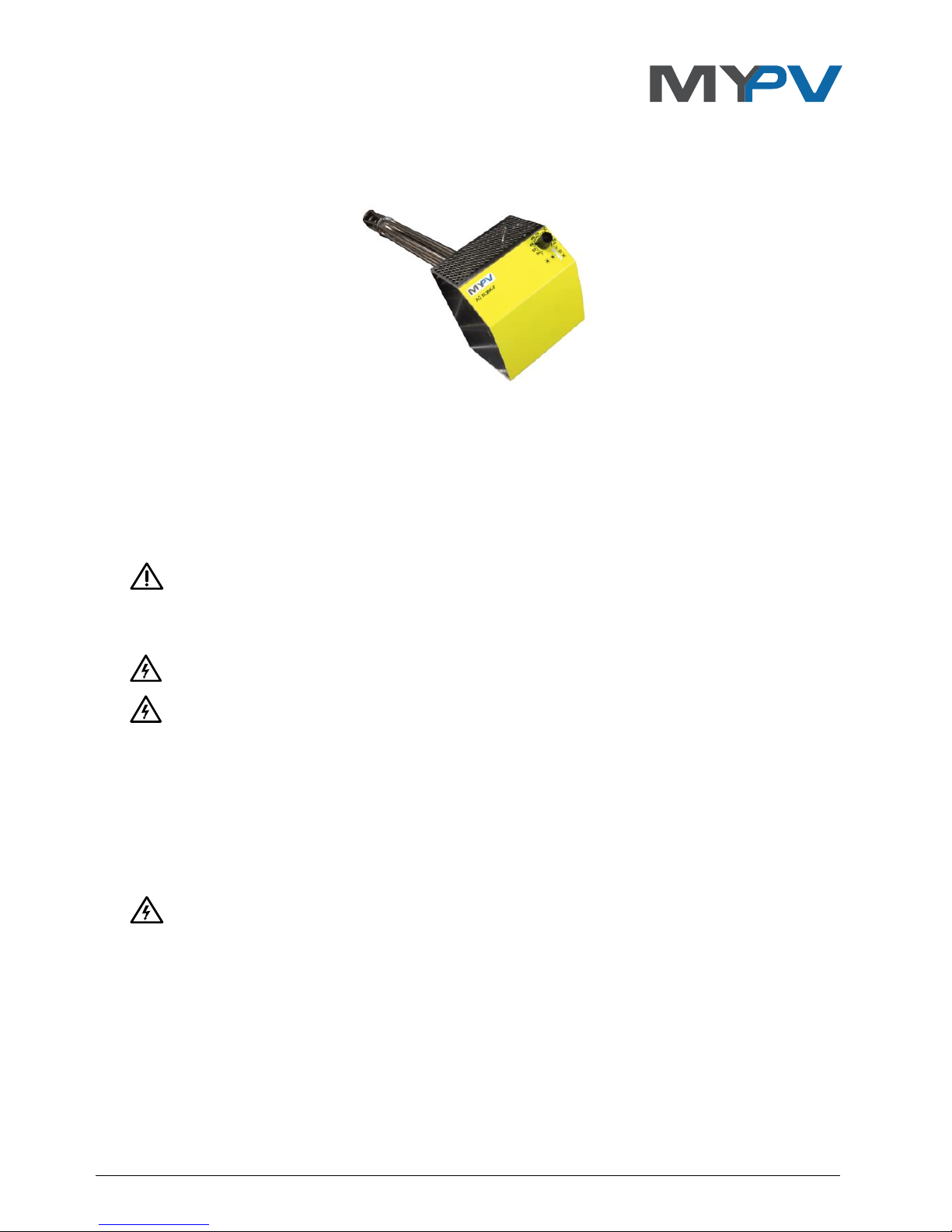
Electric PV Excess Energy Water Heater for
frequency-controlled AC coupled off-grid PV systems
Assembly- and Operation Manual
Content
1. Intended use ..................................................................................................................................... 2
2. Scope of delivery............................................................................................................................... 2
3. Safety instructions ................................................................................................................... 2
4. Exemption of Warranty and Liability .............................................................................................. 3
5. Mounting and Installation Instructions .......................................................................................... 3
6. Electrical Connection............................................................................................................... 4
7. Operation with frequency-shift inverters ............................................................................. 4
8. Controls and Indicators .................................................................................................................... 4
9. Operating status indicator ............................................................................................................... 5
10. Factory preset ................................................................................................................................... 5
11. Fuse setting with rotary knob (13 A / 16 A) .................................................................................... 5
12. Adjusting the frequency behaviour ................................................................................................ 5
13. Adjusting the maximum power ....................................................................................................... 7
14. Using multiple AC ELWA-F in a system .................................................................................. 7
15. Red LED error displays ..................................................................................................................... 8
16. Maintenance ..................................................................................................................................... 8
17. Troubleshooting ............................................................................................................................... 8
18. Disposal ............................................................................................................................................. 8
19. EU Declaration of Conformity ......................................................................................................... 9
20. Technical data ................................................................................................................................... 9

AC ELWA®-F Assembly- and Operation Manual, 170224 2
1. Intended use
The electric PV excess-energy hot water device AC ELWA-F is intended for stationary installation
in hot water storage tanks or buffer storage tanks. The device operates in combination with
frequency-shift inverters and uses excess energy for hot water production as soon as the
battery gets fully charged.
Any other use than described above may damage the product, moreover, this involves dangers
such as short circuit, fire, electric shock, etc. The safety instructions and the information on
handling in this manual and in the assembly instructions must be observed!
The product complies with the applicable National and European requirements. Company
name and product name are trademarks of my PV GmbH. All rights reserved.
2. Scope of delivery
Electric photovoltaic hot water system AC ELWA-F
IP21 cover
Assembly- and Operation Manual
3. Safety instructions
The installation must be carried out exclusively by the authorized expert.
Always comply with local regulations for mounting and connection.
Any damage caused by ignoring the installation and user manual is not covered by the
manufacturer´s warranty.
Permanent equipotential bonding of the device and the storage tank is mandatory.
Never switch on the device if the heating rod is not fully immersed.
The device is intended for use in a dry environment, the enclosure must not get wet or moist.
Danger of electric shock!
Never use the device where ammonia is present.
Never use the device in a dusty environment.
Never cover the ventilation holes of the enclosure.
Always mind the mounting position: heating rod horizontal, power cord bottom.
Avoid high (>40 °C) and low (<5 °C) ambient temperatures during storage and operation of the
device. Avoid direct sunlight.
The thermal fuse blows at 98 +/-3 °C and deactivates the device permanently.
AC supply must be fused 13 to 16 A.
In commercial facilities electrical installations have to comply with all local regulations.
This unit shall not be used by children persons with reduced physical, sensory or mental
capabilities or lack of experience and knowledge. Cleaning and user maintenance shall not be
undertaken by such individuals. Children should not play with the appliance.
AC ELWA®-F Assembly- and Operation Manual, 170224 3
4. Exemption of Warranty and Liability
Any warranty or liability is exempted for:
Injury to persons and/or damage to property caused by unintended use or in disregard of
safety- and user instructions
Consequential damage
Unauthorized modification, disassembling or other conversion of the device
Defects caused by lime scale deposits on the heating rod
5. Mounting and Installation Instructions
The installation of the device must only be carried out by authorized technical staff.
The storage tank must be drained properly.
AC ELWA-F is intended for horizontal mounting in hot water or storage tanks with 1 ½ inch
standard female threads.
The unheated section of the heating rod is 90 mm from sealing face, the length of the thread
pipe must not exceed 80 mm.
Use the O-ring seal supplied. Do not use any grease or lubrication agents. The plastic thread
must not be sealed with the help of hemp or other sealing material.
Do not apply force when screwing in the entire device until the seal is slightly pressed. Make
sure that the O-ring is properly placed in its groove. Then tighten the heating rod with a 60mm
spanner. Never exceed a torque of 80 Nm.
Never tighten the heating rod by turning the metal case of the device!
If the device is not upright (power cord bottom) after the thread has been tightened, it can be
turned gently left or right.
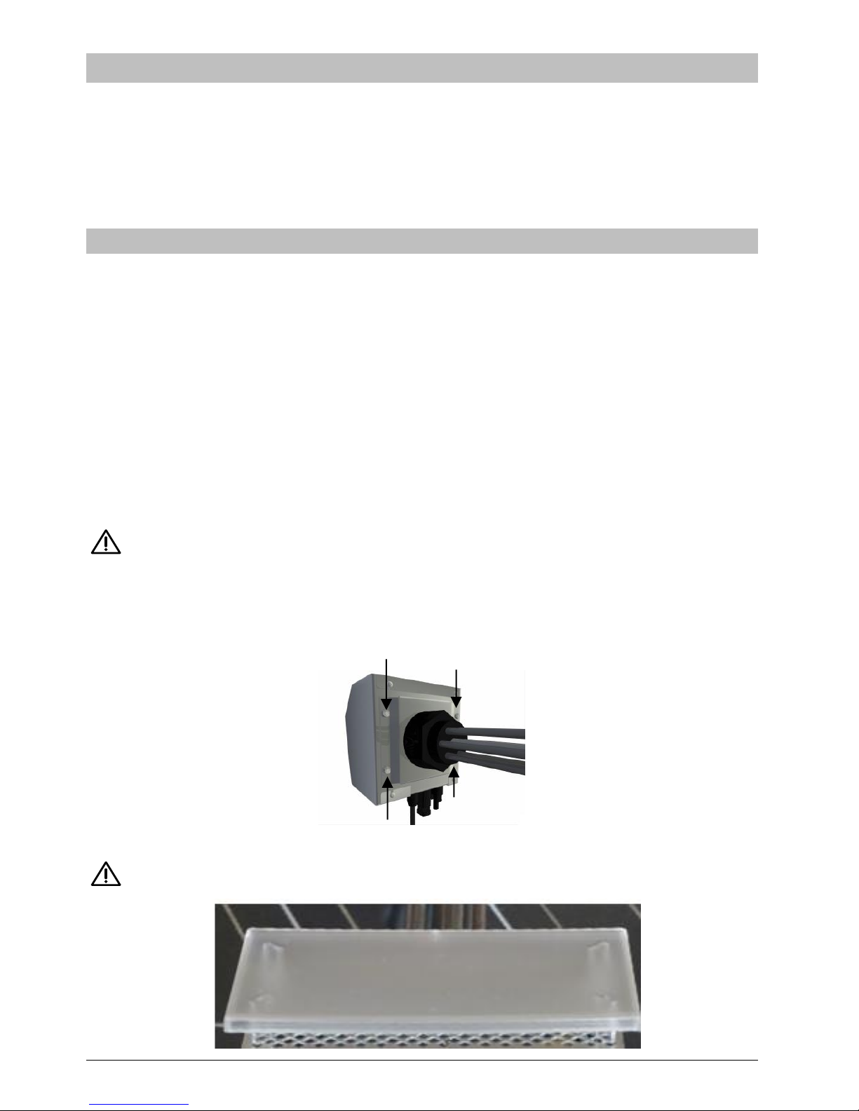
Then tighten the 4 lock nuts to fix the device:
Make sure that the heating rod is fully immersed when filling the water tank. Check for leakage.
After mounting, the IP21 cover supplied has to be attached!

AC ELWA®-F Assembly- and Operation Manual, 170224 4
6. Electrical Connection
AC ELWA-F has to be connected to an earthed socket that is protected by a 13 A or 16 A circuit
breaker.
Earthing must be provided!
Use only in systems with protective earthing and leakage current detection!
Take care of other appliances connected to the same circuit breaker, this may trigger it!
7. Operation with frequency-shift inverters
Frequency-shift inverters control battery charging in AC coupled off-grid PV systems by
changing the AC frequency.
The AC ELWA-F measures this frequency and detects if excess power is available. It controls its
heating power linearly between 0 and max. 3000 W.
It is recommended to set maximum power of the AC ELWA-F not more than half the power of
the battery inverter. The lowest adjustable maximum power limit of the AC ELWA-F is 500 watts.
Correspondingly, a power of at least 1 kW is recommended for the battery inverter.
Regarding the minimum capacity of the battery, follow the battery manufacturer's instructions!
The smaller the internal resistance of the battery, the less it can withstand load.
A minimum voltage of 24 V is recommended to limit the current. However, operation at lower
voltages is possible.
No control wire between the AC ELWA-F and the inverter is required.
8. Controls and Indicators
Rotary knob for temperature
adjustment
1-6 … AC ELWA number (setting not
required)
13 A / 16 A … fuse setting
LED green Target temperature reached
(flashes at Standby)
LED yellow Normal heating mode
LED red Error condition

AC ELWA®-F Assembly- and Operation Manual, 170224 5
9. Operating status indicator
Startup
Standby (no
excess energy
available)
Heating
Heating finished,
target temperature
reached
Setup
Mode
Frequency out
of range
Error
Legend:
LED on
LED flashes
LED off
10. Factory preset
Frequency control reaction: 50.00Hz ≙ 0 W, 51.00Hz ≙ 3,000 W (2,500 W with 13 A
fuse), linear power curve in between
16 A fuse setting
AC ELWA-F Number 1 (not relevant for frequency operation)
11. Fuse setting with rotary knob (13 A / 16 A)
At factory preset, AC ELWA-F can take up to 3,000 W from the grid (16 A fuse). For 13 A fused
sockets, the maximum power consumption can be reduced to 2,500 W.
Procedure:
1. Unplug device
2. Turn rotary knob left to spanner position
3. Plug in device
all 3 LEDs are flashing after some seconds to indicate setup mode
4. Turn rotary knob to 13 A setting
LEDs “run” from top to bottom
5. After 5 seconds of no knob turn, LEDs flash fast for 2 seconds, setting is saved in non-
volatile memory.
6. Set knob to desired cut-off temperature
7. Setting may be changed by following the procedure again (e.g. to 16 A position)
12. Adjusting the frequency behaviour
Check the settings of the frequency response of the battery inverter and the PV inverter!
To change the frequency response of the AC ELWA-F the my-PV USB-Interface is required!
This is not included in the scope of supply.
1. Install the USB interface according to the enclosed mounting and operating instructions on
the AC ELWA-F.
2. Download „Software Package AC ELWA-F.zip“ at www.my-pv.com
Use program “AC ELWA V1_XX.exe”
3. Unzip and run program (no further installation required)

AC ELWA®-F Assembly- and Operation Manual, 170224 6
4. Choose language and correct COM port under Settings Menu
AC ELWA Software connects automatically with AC ELWA-F. Current data of the device are
displayed, including AC frequency:
5. Choose „Frequency Control“ in Stettings Menu.
6. Choose desired setting, press OK. Values are stored in non-volatile memory. Readjustment
is possible anytime.
AC ELWA®-F Assembly- and Operation Manual, 170224 7
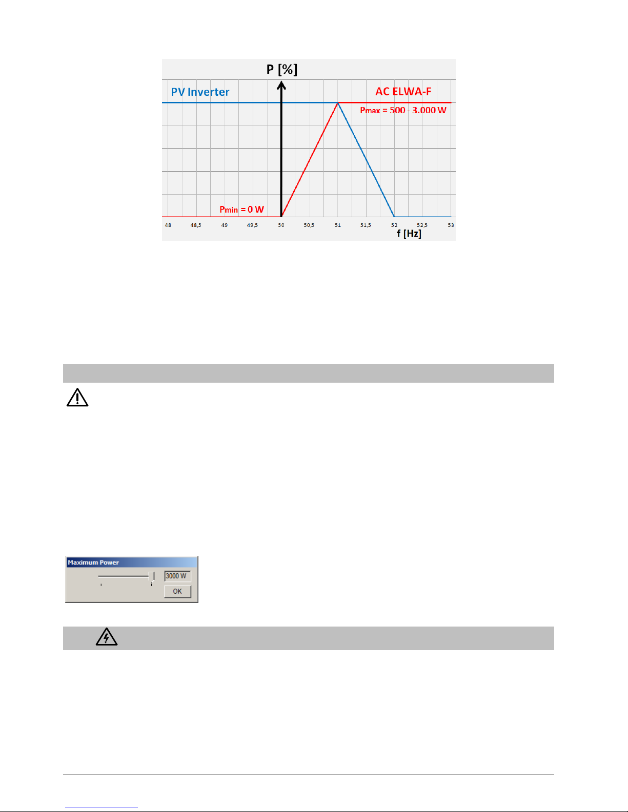
Indication for Frequency setting
Figure: relative power of the AC ELWA-F
The frequency control range of the AC ELWA-F should be set as follows:
Low setting should be at least 0.1 - 0.5 Hz above lowest frequency of the battery inverter
to avoid cut-in of AC ELWA-F at non-fully charged battery
High setting should be equal to derating start frequency of PV inverter
Difference between low and high frequency should be at least 0.5 Hz to ensure smooth
regulation behavior.
13. Adjusting the maximum power
To change the maximum power limit of the AC ELWA-F the my-PV USB-Interface is
required! This is not included in the scope of supply.
In addition to adjusting the fuse setting, the AC ELWA-F´s maximum power can be reduced to
fit to smaller battery inverters.
My-PV recommends to set maximum power of the AC ELWA-F not more than half the power of
the battery inverter. This recommendation applies in the event that loads are connected with
which the discharge capacity of the battery inverter is exceeded.
For this purpose steps of 100 watts are possible in the range between 500 and 3,000 Watts .
Choose „Maximum Power“ under Settings Menu.
The frequency curve is linear from 0 to this setting between the chosen low and high frequency.
14. Using multiple AC ELWA-F in a system
You can use multiple AC ELWA-F in a system, either on the same phase or on different phases.
The battery inverter´s power must be sufficient.
By choosing different frequency windows on the AC ELWA-F´s, heating priorities are achievable.

AC ELWA®-F Assembly- and Operation Manual, 170224 8
15. Red LED error displays
No LED: Check supply voltage.
Check circuit breaker.
Check for parallel loads on the same circuit that may have overloaded the
circuit breaker.
1x flash Over temperature fuse (98°C) blown. Unit must be serviced by authorized
staff.
2x flash Water temperature over 90°C. Unit switches off and reconnects after
temperature reduction
Remark: Water temperature is close to temperature fuse cut out point.
Check if water has been heated by external heating source, reduce cut out
temperature of this source.
3x flash Over temperature of internal electronics. Device stops and reconnects after
cool-down.
4x flash Hardware fault. Unit must be serviced by authorized staff.
6x flash Temperature probe fault. Unit must be serviced by authorized staff.
16. Maintenance
Use in hard water can lead to lime scale deposition at the heating rod especially of the target
temperature is set above 60°C. We recommend an annual check. Dismantle device from
storage tank and remove lime deposition. Never scratch the heating rod surface (corrosion
might arise).
A damaged mains cord shall be changed immediately by authorized staff.
17. Troubleshooting
The device does not contain any user serviceable parts. Call your installer for service.
18. Disposal
Keep packaging box or dispose properly.
Dispose the device according to legal regulations at the end of lifetime.

AC ELWA®-F Assembly- and Operation Manual, 170224 9
19. EU Declaration of Conformity
my-PV GmbH, Teichstrasse 43, A-4523 Neuzeug, hereby declares that the device
AC ELWA-F
complies with the following standards and regulations:
EN 55014-1, EN 55014-2, EN 60335-2-21, EN 60730-2-9, EN 61000-3-2, EN 61000-3-3, EN 62233
The above mentioned company holds documentation to proof the compliance with safety
requirements.
Neuzeug, 24.2.2017 Dr. Gerhard Rimpler, Managing Director
20. Technical data
AC ELWA-F
Mains Voltage
200 - 250 V AC
Heating power max.
3,000 W at 230 VAC
Power control
Linear frequency curve
Frequency range
47 Hz to 54 Hz
Low frequency setting 0 W
49.000-51.900 Hz
High frequency setting
49.100-52.000 Hz, 0.1 Hz above low frequency setting
Mains connector
Single phase, earthed connector, 230 V, 50 Hz
Line circuit breaker
13 A or 16 A
Power cord
2.8 m
Standby-consumption
<1.4 W
Water pressure
max. 10 bar (1 MPa)
Efficiency
>99 % at nominal power
Protection class
IP21
Operating temperature range
5 ° C to 40 ° C
Display
3 LED’s
Dimensions (LxWxD)
130 x 180 x 600 mm including heating rod
Heating rod lenght
45 cm
Heating rod thread
1 ½ Inch
Weight
2 kg including cable, without packaging
Subject to change.
my-PV GmbH
Teichstrasse 43, A-4523 Neuzeug
www.my-pv.com
 Loading...