


F250 Precision Thermometer Driver
Programmable Serial Interface Card
Series 2
USER MANUAL
Rev. P1.10
July 29, 2004
DeltaV is a trademark of Emerson Process Management, Inc © Emerson Process Management, Inc. 1998, 1999.
Printed in the U.S.A.
While this information is presented in good faith and believed to be accurate, MYNAH Technologies does not
All rights reserved.
guarantee satisfactory results from reliance upon such information. Nothing contained herein is to be construed as
a warranty or guarantee, express or implied, regarding the performance, merchantability, fitness or any other matter
with respect to the products, nor as a recommendation to use any product or process in conflict with any patent.
MYNAH Technologies reserves the right, without notice, to alter or improve the designs or specifications of the
products described herein.

POWERFUL SOLUTIONS FOR DIGITAL PLANTS
1 INTRODUCTION
1.1 Scope
This document is the User Manual for the F250 Precision Thermometer driver firmware for
the Emerson Process Management (EPM) DeltaV Control System; it provides information
required to install, configure, and maintain the driver firmware on the DeltaV Series 2
Programmable Serial Interface Card (PSIC). The reader should be familiar with EPM’s
DeltaV PSIC and connected F250 Precision Thermometer devices.
The section Document Format briefly describes the contents of each section of this manual.
System Specifications outlines hardware and software requirements for the F250 Precision
Thermometer Driver (P1.10) firmware. This driver is not available for Series 1 serial cards.
1.2 Document Format
This document is organized as follows:
Table 1
Introduction
Theory of Operation
Downloading Firmware
Configuration Information
Operational Check
DeltaV–Field Device Electrical
Interface
Technical Support
Example
Describes the scope and purpose of this document.
Provides a general functional overview of the F250
Precision Thermometer Driver.
Describes downloading procedures for the F250
Precision Thermometer Driver firmware on to the
DeltaV PSIC.
Describes procedures and guidelines for configuring
the DeltaV PSIC.
Provides tips and assistance to ensure PSIC is
properly setup and configured.
Describes the electrical interface between DeltaV
and the F250 Precision Thermometer device. Also
describes the cable pin assignments for RS-232 and
RS-422/485 communications.
Describes who to call if you need assistance.
Describes how to configure a device with input and
output datasets.
MYNAH Technologies ▪ 504 Trade Center Blvd ▪ Chesterfield, MO 63005 ▪ Telephone (636)681-1555 ▪ Fax (636) 681-1660
www.mynah.com
1

POWERFUL SOLUTIONS FOR DIGITAL PLANTS
1.3 System Specifications
The following table lists the minimum system requirements for the F250 Precision
Thermometer Driver:
Table 2
Firmware
Protocol Compatibility
Software Requirements
Minimum DeltaV Hardware
Requirements
F250 Precision Thermometer Driver Firmware
(P1.10)
F250 Mk II Precision Thermometer Operators
Handbook. F250-14-002 Issue 6
DeltaV System Software (Release 6.3.2 or later)
installed on a hardware-appropriate Windows PC
configured as a ProfessionalPlus for DeltaV
Serial Interface Port License (VE4102)
FRSI DeltaV Serial Interface Series 2, Hardware PN:
12P2506X022
FRSI DeltaV M3, M5, MD or Series 2 MD Controller,
Power Supply and 2 wide controller carrier
FRSI 8 wide I/O card carrier
MYNAH Technologies ▪ 504 Trade Center Blvd ▪ Chesterfield, MO 63005 ▪ Telephone (636)681-1555 ▪ Fax (636) 681-1660
www.mynah.com
2

POWERFUL SOLUTIONS FOR DIGITAL PLANTS
2 THEORY OF OPERATION
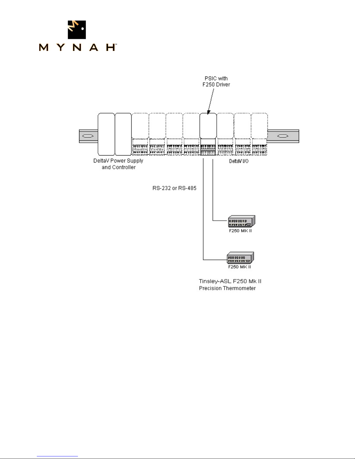
The Programmable Serial Interface Card (PSIC) has 2 ports which can be configured for
RS-232, RS-422/RS-485 Half Duplex or RS-422/RS-485 Full Duplex communications
with external devices. For communications with the F250 Precision Thermometer devices,
any mode may be used. The driver supports only one F250 device per port. Specifically,
the devices cannot be multi-dropped.
The DeltaV Serial Card Driver functionality will be as follows.
1. The driver will be flashed into the PSIC.
2. The driver will run in Master mode only and be responsible for sending commands to
the F250 units. The F250 will respond with temperature reading information, which will be
reported to DeltaV in dataset registers.
3. The two ports of the PSIC work independently, each connected to a single F250 unit.
The following shows PSIC connectivity with F250 Precision Thermometer devices.
MYNAH Technologies ▪ 504 Trade Center Blvd ▪ Chesterfield, MO 63005 ▪ Telephone (636)681-1555 ▪ Fax (636) 681-1660
www.mynah.com
3
POWERFUL SOLUTIONS FOR DIGITAL PLANTS
MYNAH Technologies ▪ 504 Trade Center Blvd ▪ Chesterfield, MO 63005 ▪ Telephone (636)681-1555 ▪ Fax (636) 681-1660
www.mynah.com
4
POWERFUL SOLUTIONS FOR DIGITAL PLANTS
3 Downloading the firmware
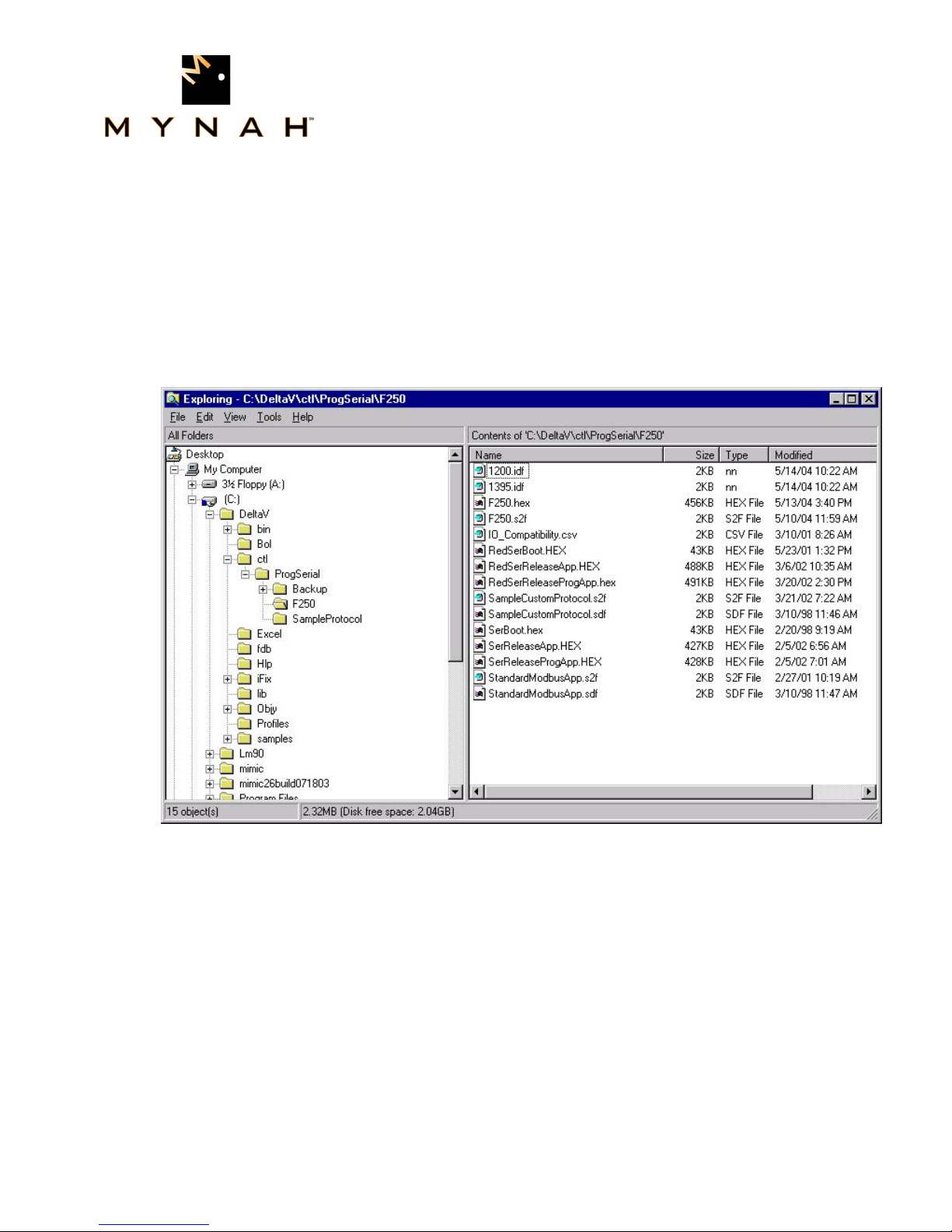
The driver software distribution comprises 15 files, distributed on a CD. These files
must be copied to the DeltaV directory on your ProPlus Workstation. The path is:
\DeltaV\ctl\ProgSerial\F250
Note that you will have to create the \F250 subdirectory. The following files will be copied:
MYNAH Technologies ▪ 504 Trade Center Blvd ▪ Chesterfield, MO 63005 ▪ Telephone (636)681-1555 ▪ Fax (636) 681-1660
www.mynah.com
5
POWERFUL SOLUTIONS FOR DIGITAL PLANTS
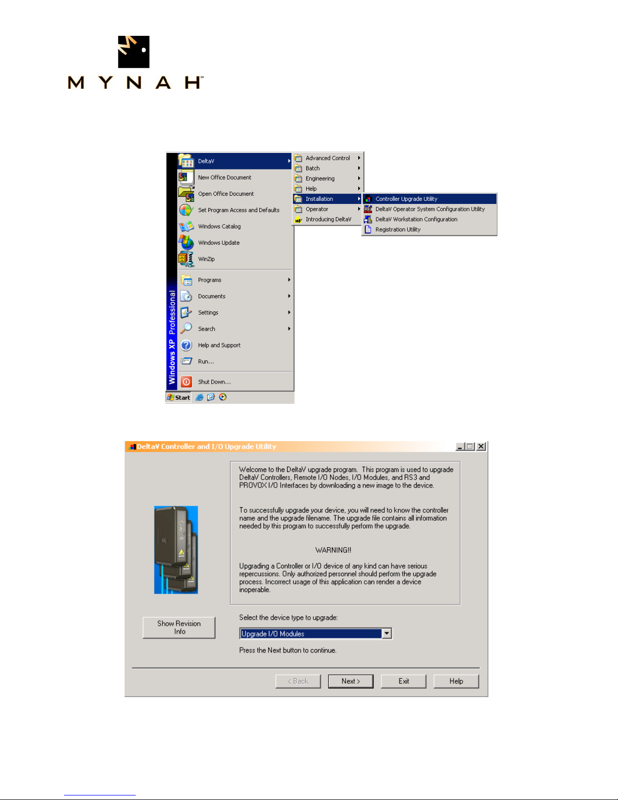
After copy completion, you are ready to program (or upgrade) the Programmable Serial Card
with the supplied custom driver software. The steps are as follows:
1. Click on the Start button and select DeltaV-> Installation-> Controller Upgrade Utility as
shown below, and the following dialog will appear:
2. Choose Upgrade I/O Modules from the drop down menu and click Next.
MYNAH Technologies ▪ 504 Trade Center Blvd ▪ Chesterfield, MO 63005 ▪ Telephone (636)681-1555 ▪ Fax (636) 681-1660
www.mynah.com
6

POWERFUL SOLUTIONS FOR DIGITAL PLANTS
3. The above dialog will appear, listing all the available Controllers in your network. From
this dialog, select the appropriate Controller and then Click Next.
4. The following dialog will appear, listing all the I/O modules in your selected Controller.
The shown list of I/O modules is an example only. Your list will be different.
MYNAH Technologies ▪ 504 Trade Center Blvd ▪ Chesterfield, MO 63005 ▪ Telephone (636)681-1555 ▪ Fax (636) 681-1660
www.mynah.com
7

POWERFUL SOLUTIONS FOR DIGITAL PLANTS
Note: The first time a standard Serial card is upgraded to the F250 Precision
Thermometer Driver, the dialog will be as shown below. When upgrading an existing
Programmable Serial Card, skip Steps 4, 5 and 6, and go to Step 7.
5. Click the Browse button and select the DeltaV path as shown below, and then click Ok.
Note that the disk drive could be C or D.
MYNAH Technologies ▪ 504 Trade Center Blvd ▪ Chesterfield, MO 63005 ▪ Telephone (636)681-1555 ▪ Fax (636) 681-1660
www.mynah.com
8

POWERFUL SOLUTIONS FOR DIGITAL PLANTS
6. Select the I/O module again as shown below and then click Next. Go to Step 9.
7. If you are upgrading an existing Programmable Serial Card, the dialog will be as shown
below. From this dialog, select the Programmable Serial Card I/O Module in the list.
MYNAH Technologies ▪ 504 Trade Center Blvd ▪ Chesterfield, MO 63005 ▪ Telephone (636)681-1555 ▪ Fax (636) 681-1660
www.mynah.com
9

POWERFUL SOLUTIONS FOR DIGITAL PLANTS
For example, we will select I/O Module 1. This will give you a dialog, from which you will
select the file path to where the driver software is located. This path will be:
\DeltaV\ctl\ProgSerial \F250\Series 2
Once you are in the specified directory, you will need to select the following file:
F250.S2F
This is shown in the following dialog.
MYNAH Technologies ▪ 504 Trade Center Blvd ▪ Chesterfield, MO 63005 ▪ Telephone (636)681-1555 ▪ Fax (636) 681-1660
www.mynah.com
10

POWERFUL SOLUTIONS FOR DIGITAL PLANTS
8. After selecting the .S2F file, Click on Open. This dialog will close and you will be back to
the following:
9. In this dialog, Click Next again. You will get the following dialog, confirming the
Controller and I/O Module to program.
10. Click Next and the I/O Module upgrade process will begin. After completion, you will
receive the following dialog, indicating success.
MYNAH Technologies ▪ 504 Trade Center Blvd ▪ Chesterfield, MO 63005 ▪ Telephone (636)681-1555 ▪ Fax (636) 681-1660
www.mynah.com
11

POWERFUL SOLUTIONS FOR DIGITAL PLANTS
11. This completes the I/O Module upgrade process.
MYNAH Technologies ▪ 504 Trade Center Blvd ▪ Chesterfield, MO 63005 ▪ Telephone (636)681-1555 ▪ Fax (636) 681-1660
www.mynah.com
12

POWERFUL SOLUTIONS FOR DIGITAL PLANTS
4 CONFIGURATION INFORMATION
The DeltaV Explorer view of a configuration containing a Programmable Serial Card will
be as follows, where C01 has a card type of Programmable Serial Card, P01 and P02
are the ports on the card, DEVXX are pseudo devices attached to the ports, and DSXX
are configured Datasets for each device.
Note: There are 3 possible configurations each is shown below. Only one type can
be used on a port at any time.
Dataset Configuration 1
Table 3a
Port Devices Dataset Mode Type and Number
Description
of Values
P01
DEV01
DS1 Input Floating Point, 1
Value
Reads the
current PRT
Control Network
Controller Name
I/O
C01 - Programmable Serial Card
P01
DEV01
DS01 - Current PRT
Reading
MYNAH Technologies ▪ 504 Trade Center Blvd ▪ Chesterfield, MO 63005 ▪ Telephone (636)681-1555 ▪ Fax (636) 681-1660
www.mynah.com
13

POWERFUL SOLUTIONS FOR DIGITAL PLANTS
Dataset Configuration 2
Table 3b
P01
DEV01
DS1 Input Floating Point, Up
to 16 Values.
DS2 Input Floating Point, Up
to 16 Values.
Control Network
Controller Name
I/O
C01 - Programmable Serial Card
P01
DEV01
DS01 - All Thermometers
on Input A
DS02 - All Thermometers
on Input B
Reads up to 16
thermometers
on Input A
Reads up to 16
thermometers
on Input B
Dataset Configuration 3
Table 3c
P01
DEV01
DS1 Input Floating Point, 3
Values
Reads Input A,
Input B, then AB
Control Network
Controller Name
I/O
C01 - P rogram mable Serial Card
P01
DEV01
MYNAH Technologies ▪ 504 Trade Center Blvd ▪ Chesterfield, MO 63005 ▪ Telephone (636)681-1555 ▪ Fax (636) 681-1660
www.mynah.com
14
DS01 - Input A, Input B,
A-B

POWERFUL SOLUTIONS FOR DIGITAL PLANTS
4.2 Device Configuration
Specify devices, as shown above. There will be one device under each port.
4.3 Dataset Configuration
MYNAH Technologies ▪ 504 Trade Center Blvd ▪ Chesterfield, MO 63005 ▪ Telephone (636)681-1555 ▪ Fax (636) 681-1660
4.1 Port Configuration
First, enable the port. Then click on the Advanced Tab and Master mode. Slave is not
supported. Specify the retry count, message timeout value in milliseconds, and message
delay time. In most cases, you can leave these at their default values. Next, click on the
Communications Tab and specify the Port type. The Port type will be RS-232. In general,
RS-232 will be used for F250 communications, unless there are distance limitations. If the
F250 is more than 50 feet from the PSIC, RS-485 should be used. Lastly, select the Baud
rate, Parity, Data bits and Stop bits parameters; these must match the F250 settings.
Datasets contain the F250 information, and must be configured as described in Table 3.
4.3.1 Data Direction:
The Data Direction for should always be defined as Input.
4.3.2 Output Mode:
Output mode and Read back items are not used. These should be left as default.
4.3.3 DeltaV Data Type:
All datasets will be configured as type Floating Point.
4.3.4 DeviceDataType
The following device data types are available. Only one configuration should be chosen.
For example if Configuration 1 is desired only 1 dataset is required. If Configuration 2 is
desired then two datasets are required one with DeviceDataType 1 and the other with
DeviceDataType 2.
Table 4
DeviceDataType Description
0 Configuration 1 – Read Only the currently selected PRT.
1 Configuration 2 – Read each device attached to Input A
2 Configuration 2 – Read each device attached to Input B
3 Configuration 3 – Read A, B, and A-B Differential
www.mynah.com
15

4.3.5 Data Start Address and Number of Values
The Start Address for each dataset is not used and can be left as default 0. The Number of
values for Configuration 1 is 1 register. For Configuration 2, the number of values depends
on the number of attached devices to each dataset. Configuration 3 requires 3 Registers.
4.3.6 Special Data
The following device data types use special data registers to specify additional parameters
required for reading from the F250:
Table 5
DeviceDataType Special Data #
(0) Configuration 1 UNUSED
(1) Configuration 2 – Input A Special Data 1: Number of Devices on
(2) Configuration 2 – Input B Special Data 1: Number of Devices on
(1&2)Configuration 2
(3) Configuration 3 – A, B, and A-B Differential UNUSED
POWERFUL SOLUTIONS FOR DIGITAL PLANTS
Input A
Input B
Special Data 2:
0 – Use trailing Line Feed character.
1 – Omit Line Feed character.
Special Data 5: Delay in milliseconds to
wait for F250 to switch channels.
MYNAH Technologies ▪ 504 Trade Center Blvd ▪ Chesterfield, MO 63005 ▪ Telephone (636)681-1555 ▪ Fax (636) 681-1660
www.mynah.com
16

POWERFUL SOLUTIONS FOR DIGITAL PLANTS
5 Operational Check
5.1 Scope
The following sections provide some assistance to ensure the interface is working
properly.
5.2 Verify Hardware and Software Version Number
To begin the DeltaV Diagnostic tool select Start-> DeltaV-> Operator-> Diagnostics. In
The following information will be displayed:
: : :
HwRev Hardware Revision 1.10 (or later)
SwRev Software Revision 2.3 (or later)
The user can verify that the F250 driver has been installed using the DeltaV Diagnostics
tool. The Diagnostics tool will show the Hardware Revision No. (HwRev) and the
Software Revision No. (SwRev).
the Diagnostics tool expand the Controller, I/O and then double click on the
Programmable Serial Interface Card that has the driver installed.
5.3 Verify Configuration
• Verify port configuration: The serial port must be enabled. User needs to make sure
communication settings such as baud rate, parity, and number of data bits match the
field device settings.
• Verify dataset configuration: The datasets configured must be as shown above.
5.4 Verify I/O Communication With Control Studio
User can create I/O modules in the control studio to verify correct values are being
written out. An example module is shipped with the distribution. This module shows
methods for writing text to the datasets and also how to handle time.
5.5 Using Diagnostics
• Verify PSIC communication: Select the PSIC on Diagnostics and press the right
mouse button. Select Display Real -Time Statistics from the drop down menu. If the
Programmable Serial Interface Card is functioning then the user will see the Valid
Responses counter and the Async and/or Sync Transactions counters incrementing.
There will not be any error counting up.
MYNAH Technologies ▪ 504 Trade Center Blvd ▪ Chesterfield, MO 63005 ▪ Telephone (636)681-1555 ▪ Fax (636) 681-1660
www.mynah.com
17

POWERFUL SOLUTIONS FOR DIGITAL PLANTS
• Verify port statistics: Select the Port on the Programmable Serial Interface Card and
press the right mouse button. Then select Display Port Statistics form the drop down
menu. Verify that the port communications statistics are being displayed properly
and are counting as expected for the protocol’s functionality.
• Verify dataset values: Select a dataset and press the right mouse button. Select
View Dataset Registers from the Drop down window. Verify that the dataset values
are displayed as expected.
5.6 LED Indication
The Yellow LED for the port should be on solid when all communications on that port are
valid. The Yellow LED should be blinking if there is some valid communications and
some communications with errors on that port. The Yellow LED should be OFF if there
are no valid communications on that port.
MYNAH Technologies ▪ 504 Trade Center Blvd ▪ Chesterfield, MO 63005 ▪ Telephone (636)681-1555 ▪ Fax (636) 681-1660
www.mynah.com
18

POWERFUL SOLUTIONS FOR DIGITAL PLANTS
6 DeltaV–Field Device Electrical Interface
The electrical interface between DeltaV and field devices conforms to the RS-232 and
RS-422/485 standards.
Each PSIC has 2 ports, which function independently. The distance between the serial
card and the field device can be as much as 5000 feet, per the RS-422/485 standard.
When using RS-232, the distance is limited to 50 feet. Section 6.1 shows the pin
assignments for the PSIC serial terminal block.
6.1 Pin Assignments for DeltaV PSIC
RS-232 Standard
Table 6
Terminal Number Signal Description
1 Port 1 - Isolated Ground (GND)
2 Unused
3 Port 1 – Transmit Data (TxD)
4 Unused
5 Port 1 – Receive Data (RxD)
6 Unused
7 Port 1 – Data Terminal Ready (DTR)
8 Port 1 – Data Set Ready (DSR)
9 Port 2 - Isolated Ground (GND)
10 Unused
11 Port 2 – Transmit Data (TxD)
12 Unused
13 Port 2 – Receive Data (RxD)
14 Unused
15 Port 2 – Data Terminal Ready (DTR)
16 Port 1 – Data Set Ready (DSR)
MYNAH Technologies ▪ 504 Trade Center Blvd ▪ Chesterfield, MO 63005 ▪ Telephone (636)681-1555 ▪ Fax (636) 681-1660
www.mynah.com
19

POWERFUL SOLUTIONS FOR DIGITAL PLANTS
RS-422/485 Half Duplex Standard
Table 7
Terminal Number Signal Description
1 Port 1 – Isolated Ground (GND)
2 Port 1 - Data +
3 Unused
4 Port 1 - Data -
5 Unused
6 Unused
7 Unused
8 Unused
9 Port 2 – Isolated Ground (GND)
10 Port 2 – Data +
11 Unused
12 Port 2 - Data -
13 Unused
14 Unused
15 Unused
16 Unused
RS-422/485 Full Duplex Standard
Table 8
Terminal Number Signal Description
1 Port 1 – Isolated Ground (GND)
2 Port 1 – TxD +
3 Unused
4 Port 1 – TxD -
5 Unused
6 Port 1 – RxD +
7 Unused
8 Port 1 – RxD -
9 Port 2 – Isolated Ground (GND)
10 Port 2 – TxD +
11 Unused
12 Port 2 – TxD -
13 Unused
14 Port 2 – RxD +
15 Unused
16 Port 2 – RxD -
MYNAH Technologies ▪ 504 Trade Center Blvd ▪ Chesterfield, MO 63005 ▪ Telephone (636)681-1555 ▪ Fax (636) 681-1660
www.mynah.com
20

POWERFUL SOLUTIONS FOR DIGITAL PLANTS
6.2 Wiring Connections
In general, the figure below shows the connections between the Field Device and the
PSIC termination block. For additional DeltaV cabling information, please refer to the
DeltaV Books Online documentation. For F250 cabling/jumper information, refer to F250
Mk II Precision Thermometer Operators Handbook F250-14-002 Issue 6, Section 9.2.
Term Block - RS-232 Port1 F250 RS232C Interface
1 - GND
3 - TXD
5 - RXD
7 - DTR
8 - DSR
Term Block - RS-422 Full
Duplex Port1
1 - GND
2 - TX+
4 - TX-
6 - RX+
8 - RX-
5 - GND
2 - RXD
3 - TXD
F250 RS232C Interface
5 - Gnd
2 - RX+
7 - RX-
3 - TX+
8 - TX-
MYNAH Technologies ▪ 504 Trade Center Blvd ▪ Chesterfield, MO 63005 ▪ Telephone (636)681-1555 ▪ Fax (636) 681-1660
www.mynah.com
21

POWERFUL SOLUTIONS FOR DIGITAL PLANTS
7 Technical Support
For technical support or to report a defect, please give Mynah Technologies a call at (636)
681-1555. If a defect is discovered, please document it in as much detail as possible and
then fax your report to us at (636) 681-1660.
For Product functionality questions, ask for the people in the following order:
1. David Story
2. Tony Kerr
For Commercial issues, ask for people in the following order:
1. Martin Berutti
2. Jane Wagner
You can also send us your questions via e-mail. Our address is:
support@mynah.com
Thank you for using DeltaV.
MYNAH Technologies ▪ 504 Trade Center Blvd ▪ Chesterfield, MO 63005 ▪ Telephone (636)681-1555 ▪ Fax (636) 681-1660
www.mynah.com
22
 Loading...