

MM-SDM630-2C
Multi-Channel DIN Rail Smart Energy Meter
DIN RAIL SMART METER
FOR SINGLE AND THREE PHASE
ELECTRICAL SYSTEMS
USER MANUAL V4.1
1. Introduction
MM-SDM630-2C measures and displays the characteristics of
two three phase four wires circuits or 6 single phase circuits,
including voltage, frequency, current, power and active and
reactive energy, imported or exported. Energy is measured in
terms of kWh, kVArh. Maximum demand current can be
measured over preset periods of up to 60 minutes. In order
to measure energy, the unit requires voltage and current
inputs in addition to the supply required to power the
product. The requisite current input(s) are obtained via
current transformers (CT).
This meter can be congured to work with a wide range
of CTs, giving the unit a wide range of operation. Built-in
interfaces provide pulse and RS485 Modbus RTU outputs.
Conguration is password protected.
1.1 Unit Characteristics
The Unit can measure and display electronic information of
multi-channels:
• L-N voltage and THD% (total harmonic distortion) of
all phases
• Line Frequency
• Currents, Current demands and current THD% of all
phases
• Power, maximum power demand and power factor
• Active energy imported and exported
• Reactive energy imported and exported
The unit has password-protected set-up screens for:
• Changing password
• Supply system selection 1phase2wire, 3phase 4wires
• CT Ratio (1 to9999 )
• PT ratio (1 to 9999)
• Demand Interval time
• Reset for demand measurements
• Pulse output duration
A pulse output indicates real-time energy measurement. An
RS485 output allows remote
monitoring from another display or a computer.
1.2 Current Transformer Primary Current
The unit can be congured to operate with CT ratio between
Primary Current and Secondary Current. The secondar y CT
has two options: 1A / 5A
1.3 RS485 Serial - Modbus RTU
This uses an RS485 serial port with Modbus RTU protocol
to provide a means of remotely monitoring and controlling
the Unit
Set-up screens are provided for setting up the RS485 port.
1.4 Pulse Output
This provides 2 pulse outputs referring the energy consump-
tion of two circuits. Both pulse outputs are congurable.
The pulse width for active energy can be set from the Set-up
menu.
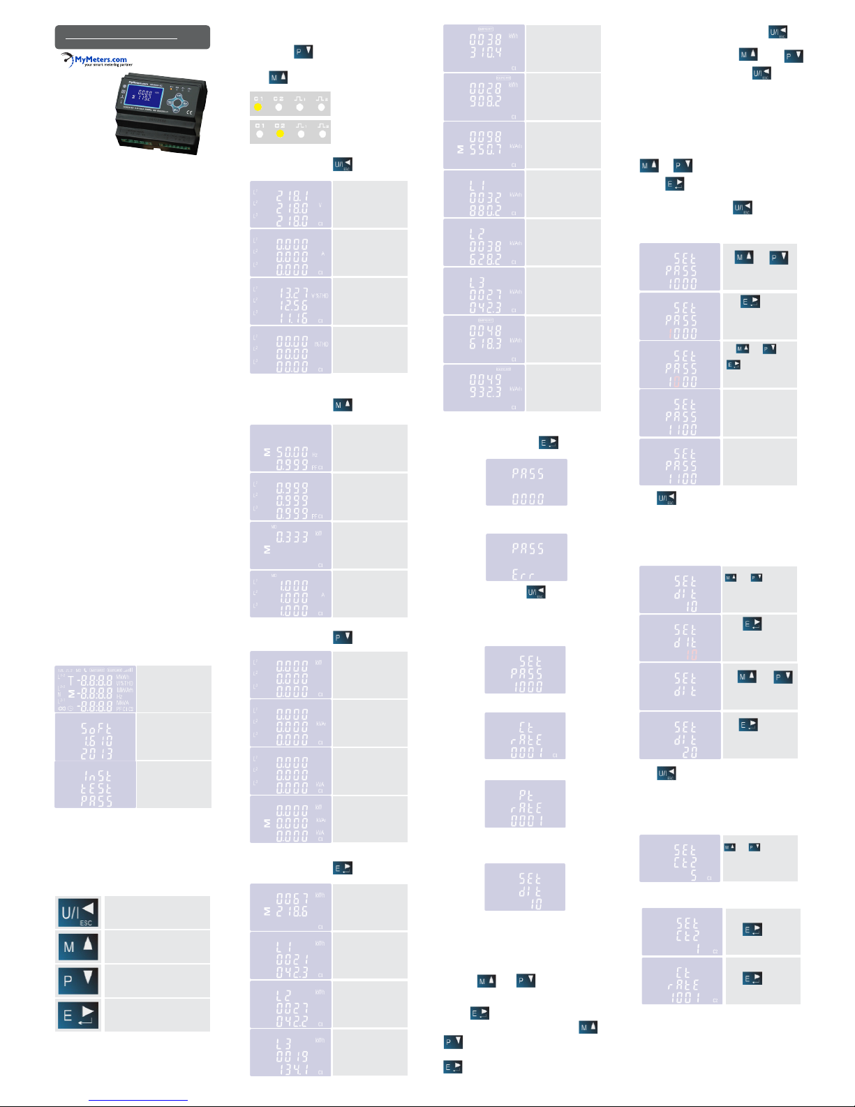
2. Start Up Screens
The rst screen lights all
display segments and can be
used as a display check.
The second screen
indicates the rmware
installed in the unit and its
build number.
Next the unit performs a
self-test and indicates if the
test passes.
After a short delay, the screen will display active energy
measurements.
3. Measurements
The MM-SDM630-2C measures all important electrical
parameters, which is shown on the LCD display and approachable via RS485. On the front panel there are four sensitive
buttons and four LED indicators.
The buttons operate as follows:
Selects the Voltage and Current display
screens In Set-up Mode, this is the
“Left” or “Back” button.
Select the Frequency and Power factor
display screens In Set-up Mode, this is
the “Up” button.
Select the Power display screens
In Set-up Mode, this is the “Down”
button.
Select the Energy display screens
In Set-up mode, this is the “Enter” or
“Right” button.
The default display after the meter is power on, the LCD
show “C1” circuit information.The way to shift “C1” circuit
information to “C2” circuit information is by pressing the
“Down” button .
If the meter are showing “C2”, and the user want to shift
it to be “C1” circuit, then he shall keep pressing the “UP”
button .
(Circuit 1)
(Circuit 2)
3.1 Voltage and Current
Each successive pressing of the button selects a
new range:
Phase to neutral voltages
Current on each phase
Phase to neutral voltage
THD%
Current THD% for each
phase
3.2 Frequency and Power Factor and
Demand
Each successive pressing of the button selects a
new range:
3.3 Power
Each successive pressing of the button selects a
new range:
Frequency
Power factor (total)
Power factor of each phase
Max. Power demand
Max. Current demand
Instantaneous active power
(kW)
Instantaneous reactive
power (kVAr)
Instantaneous Volt-amps
(KVA)
Total kW, kVAr, kVA
Total active energy in kWh
C1-L1 kwh
C1-L2 kwh
Imported active energy
in kWh
Exported active energy
in kWh
Total reactive energy
in kVAh
C1-L1 kVarh
C1-L2 kVarh
C1-L3 kVarh
Imported reactive energy
in kVArh
Exported reactive energy
in kVArh
4. Setting Up
To enter set-up mode, pressing the button for 3
seconds, until the password screen appears.
Setting up is password-protected so you must enter the
correct password (default ‘1000’) before processing. If an
incorrect password is entered, the display will show: PASS Err
To exit setting-up mode, press repeatedly until the
measurement screen is restored.
4.1 Set-up Menu Structure
Change password
nnnn 4-digit number-default ‘1000’
CT Set the value of the CT ratio
nnnn 4-digit number 0001~9999.v
PT set the value of PT Ratio
nnnn 4-digit number 0001~9999.
DIT Demand Integration Time
This is the period in minutes over which the current and
power readings are integrated for maximum demand measurement. Options are: 5 , 10, 15, 30 and 60minutes.
4.2 Set-up Entry Methods
Some menu items, such as password and CT, require a
four-digit number entry while others, such as supply system,
require selection from a number of menu options.
4.2.1 Menu Option Selection
5) Having completed a parameter setting, press to
return to a higher menu level. The SET indicator will be
removed and you will be able to use the and
buttons for further menu selection.
6) On completion of all setting-up, press repeatedly
until the measurement screen is restored.
4.2.2 Number Entry Procedure
When Setting up the unit , some screens require the entering
of a number. In par ticular, on entry to the setting up section, a
password must be entered. Digits are set individually, from left
to right.The procedure is as follows:
1)The current digit to be set ashes and is set using the
and buttons.
2) Press to conrm each digit setting. The SET
indicator appears after the last digit has been set.
3) After setting the last digit, press to exit the number setting routine. The SET indicator will be removed.
4.3 Change Password
Use and to
choose the change
password option.
Press to enter the
change password routine.
The new password screen
will appear with the rst
digit ashing.
Use and to set
the rst digit and press
to conrm your
selection. The next digit
will ash.
Repeat the procedure for
the remaining three digits
After setting the last digit,
SET will show.
Press to exit the number setting routine and return
to the Set-up menu. SET will be removed.
4.4 DIT Demand Integration Time
This sets the period in minutes over which the current and
power readings are integrated for maximum demand measurement.The options are: 5, 10,15 30,60 minutes.
From the set-up menu, use
and buttons
to select the dIT option.
The screen will show the
currently selected integration time.
Press to enter
the selection routine. The
current time interval
will ash.
Use and
buttons to select the time
required.
Press to conrm
selection. SET indicator
will appear.
Press to exit the DIT selection routine and return
to the menu.
4.5 CT
The CT option sets the current ratio (1~9999) and secondary
current (CT2 1A/5A) of the current transformer (CT) that
wires to the meter.
From the Set-up menu, use
and buttons
to select the CT option.
The screen will show the
current CT primary current
value.
C1.CT2 -> Circuit 1
C2.CT2 -> Circuit 2
There are four LED indicators on the front panel , namely C1,
C2, Pulse1 and Pulse2. The unit can measures and displays data
of two three phase circuits: C1 circuit and C2 circuit. If C1
LED shows, that means the reading on the LCD are for C1
circuit. While C2 is there, it means the measurements on the
LCD are for C2 circuit.
Each successive pressing of the button selects a
new range:
3.4 Energy Measurements
C1-L3 kwh
1) Use the and buttons to select the
required item from the menu shown in section 4.1. Selection
does not roll over between bottom and top of list.
2) Press to conrm your selection
3) If an item ashes, then it can be adjusted by the and
buttons. If not, there maybe a further layer.
4) Having selected an option from the current layer, press
to conrm your selection. The SET indicator will
appear.
Secondary CT setting
Press to enter
the CT secondary current
selection routine. 5A/1A
Set CT Ratio Value
Press to enter the
CT Ratio. The range is from
0001~9999.
Example: if set the ratio to be 100, that means the primary
current is secondary current x100.
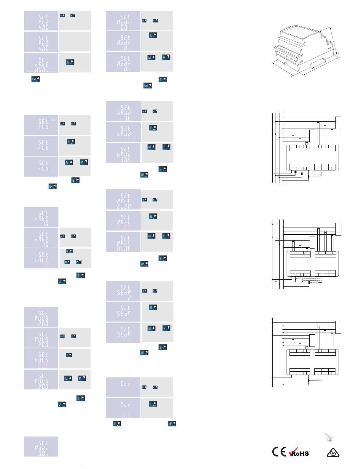
4.6 PT
The PT option sets the secondary voltage (PT2 100~500V) of
the Voltage transformer (PT) that wires to the meter and the
PT ratio between PT1 to PT2. The default value is 400V for
Secondary PT (L-L), and the ratio between PT1 and PT2 is 1.
Secondary PT setting
The setting method is same
as Primary voltage setting
PT1. Max PT2 value is 500V
Set PT Ratio Value
Press to enter the
PT Ratio. The range is from
0001~9999.
From the Set-up menu, use
and buttons
to select the PT option.
The screen will show the
voltage PT secondary
voltage value.
Press to exit the system selection routine and return
to the menu. SET will disappear and you will be returned to
the main Set-up Menu.
4.7 Pulse Output
This option allows you to congure the pulse output. The
output can be set to provide 2 pulses, Pulse 1 is lock to C1,
and Pulse 2 is lock to C2. The setting will be effective for both
pulse outputs. Use this section to set up the pulse output
(Units: kWh, kVarh)
From the Set-up menu, use
and buttons
to select the Pulse output
option.
Press to enter the
selection routine. The unit
symbol will ash.
Use and
buttons to choose kWh
or kVArh.
On completion of entry procedure, press to conrm
the setting and press to return to the main set
up menu.
4.7.1 Pulse Rate
Use this to set the energy represented by each pulse. Rate can
be set to 1 pulse per 0.01/0.1/1/10/100/1000kWh/KVArh.
(It shows 1 impulse =
10kWh/kVArh)
Press to enter the
selection routine. The cur-
rent setting will ash. Use
and and buttons
to choose pulse rate.
From the Set-up menu, use
and buttons
to select the Pulse Rate
option.
On completion of the entry procedure, press to
conrm the setting and press to return to the main
set up menu.
4.7.2 Pulse Duration
The energy monitored can be active or reactive and the pulse
width can be selected as 200, 100 or 60ms.
(It shows pulse width
of 200ms)
From the Set-up menu, use
and buttons
to select the Pulse width
option.
Press to enter the selection routine. The current
setting will ash.
200/100/60ms
Use and
buttons to choose pulse
width.
On completion of the entry procedure, press to
conrm the setting and press to return to the main
set up menu.
4.8 Communication
There is a RS485 port can be used for communication using
Modbus RTU protocol. For Modbus RTU, parameters are
selected from Front panel.
From the Set-up menu, use
and buttons to
select the Address ID.
Press to enter
the selection routine. The
current setting will be
ashing.
Use and
buttons to choose Modbus
Address (001 to 247).
On completion of the entry procedure, press button
to conrm the setting and press button to return to
the main set-up menu.
4.8.2 Baud Rate
From the Set-up menu, use
and buttons to
select the Baud rate option.
Press to enter
the selection routine. The
current setting will ash.
Use and
buttons to choose Baud
rate 2.4k, 4.8k, 9.6k, 19.2k,
38.4k.
On completion of the entry procedure, press to
conrm the setting and press to return to the main
set-up menu.
4.8.3 Parity
From the Set-up menu, use
and buttons to
select the Parity option.
Press to enter
the selection routine. The
current setting will ash.
Use and
buttons to choose Parity
(EVEN / ODD / NONE).
Default is NONE.
On completion of the entry procedure, press to
conrm the setting and press to return to the main
set-up menu.
4.8.4 Stop Bits
From the Set-up menu, use
and buttons to
select the Stop Bit option.
Press to enter
the selection routine. The
current setting will ash.
Use and
buttons to choose Stop Bit
(2 or 1).
On completion of the entry procedure, press to
conrm the setting and press to return to the main
set-up menu.
5. Specications
5.1 Measured Parameters
The unit can monitor and display the following parameters of
a single phase, 3-phase 4-wire supply.
5.1.1 Voltage and Current
• Phase to neutral voltages 100 to 289V a.c.
• Voltages between phases 173 to 500V a.c.
• Percentage total voltage harmonic distortion (THD%) for
each phase to N
• Percentage voltage THD% between phases
• Current on each phase – 1 to 9999A range, set by external
current transformer(s) (CTs)
• Current THD% for each phase
5.1.2 Power Factor and Frequency and
Max. Demand
• Frequency in
• Hz Instantaneous power
• Power 0 to 3600 MW
• Reactive Power 0 to 3600 MVAr
• Volt-amps 0 to 3600 MVA
• Maximum demanded power since last
• Demand reset Power factor
• Maximum neutral demand current, since the last Demand
reset
5.1.3 Energy Measurements
• Imported active energy 0 to 9999999.9 kWh
• Exported active energy 0 to 9999999.9 kWh
• Imported reactive energy 0 to 9999999.9 kVArh
• Exported reactive energy 0 to 9999999.9 kVArh
• Total active energy 0 to 9999999.9 kWh
• Total reactive energy 0 to 9999999.9 kVArh
5.2 Measured Inputs
Voltage inputs through 4-way xed connector with 2·5mm2
stranded wire capacity. Line frequency measured from L1
voltage or L3 voltage.
Three current inputs (six physical terminals) with 2.5mm2
stranded wire capacity for connection of external CTs.
Nominal rated input current 5A or 1A a.c. Rms.
5.3 Accuracy
Voltage 0.5% of range maximum
Current 0.5% of nominal
Frequency 0.2% of mid-frequency
Power factor 1% of unity (0.01)
Active power (W) ±1% of range maximum
Reactive power (VAr) ±1% of range maximum
Apparent power (VA) ±1% of range maximum
Active energy (Wh) Class 1 IEC 62053-21
Reactive energy (VARh) ±1% of range maximum
Total harmonic distortion 1% up to 31st harmonic
5.4 Power Supply
Two-way xed connector with 2.5mm2 stranded wire capacity.
The meter is powered from Phase L1. The user must make
sure the meter Phase 1 has power on.
5.5 Interfaces for External Monitoring
Three interfaces are provided:
• an RS485 communication channel that can be programmed
for Modbus RTU protocol.
• an output indicating real-time measured energy.
(congurable)
• an pulse output 3200imp/kWh (not congurable).
The Modbus conguration (Baud rate etc.) and the pulse
output assignments (kW/kVArh, import/export etc.) are
congured through the Set-up screens.
5.5.1 Pulse Output
The pulse output can be set to generate pulses to represent
kWh or kVArh.
Rate can be set to generate 1 pulse per:
0.01 = 10 Wh/VArh
0.1 = 100 Wh/VArh
1 = 1 kWh/kVArh
10 = 10 kWh/kVArh
100 = 100 kWh/kVArh
1000 = 1000 kWh/kVArh
Pulse width 200/100/60 ms.
5.5.2 RS485 Output for Modbus RTU
For Modbus RTU, the following RS485 communication
parameters can be congured from the Set-up menu:
Baud rate 2400, 4800, 9600, 19200, 38400
Parity none/odd/even
Stop bits 1 or 2
RS485 network address nnn – 3-digit number, 001 to 247
MyMeters.com
Unit 4, 59 Beattie St, Kallangur QLD 4503 Australia
Tel: 1300 METERS (1300 638 377)
Email: info@mymeters.com
web: www.mymeters.com
MID
7.3 Six Circuits Single Phase Two Wire
7.2 One Circuit Three Phase Four Wire +
Three Circuits Single Phase Two Wire
7.1 Two Circuits Three Phase Four Wire
7. Installation
6. Dimensions
105mm
35mm
92mm
65mm
4.8.1 RS485 Address
(The range is from 001 to 247)
4.9 CLR
The meter provides a function to reset the maximum demand
value of current and power.
From the Set-up menu, use
and buttons to
select the reset option.
Press to enter the
selection routine. The dlt
will ash.
Press button to conrm the setting and press
to return to the main set up menu.
Modbus™ Word order Hi/Lo byte order is set automatically
to normal or reverse. It cannot be congured from the
set-up menu.
5.6 Reference Conditions of Inuence
Quantities
Inuence Quantities are variables that affect measurement
errors to a minor degree. Accuracy is veried under nominal
value (within the specied tolerance) of these conditions.
• Ambient temperature 23°C ±1°C
• Input waveform 50 or 60Hz ±2%
• Input waveform Sinusoidal (distortion
factor < 0.005)
• Magnetic eld of external origin Terrestrial ux
5.7 Environment
• Operating temperature -25°C to +55°C*
• Storage temperature -40°C to +70°C*
• Relative humidity 0 to 90%, non-condensing
• Altitude Up to 3000m
• Warm up time 1 minute
• Vibration 10Hz to 50Hz, IEC 60068-
2-6, 2g
• Shock 30g in 3 planes
CT3
CT2
CT1
CT3
CT2
CT1
Circuit 1
Circuit 2
N L3 L2 L1
1a fast blow fuses
CT input for Circuit 1 CT input for Circuit 2
L32 L31 L22 L21 L12 L11 L32 L31 L22 L21 L12 L11
Voltage Input Pulse 1Pulse 2 RS485
N L3 L2 L1 - + - + B A
CT3
CT2
CT1
CT3
CT2
CT1
Circuit 1
Circuit 2
N L3 L2 L1
1a fast blow fuses
CT input for Circuit 1 CT input for Circuit 2
L32 L31 L22 L21 L12 L11 L32 L31 L22 L21 L12 L11
Voltage Input Pulse 1
Pulse 2
RS485
N L3 L2 L1 - + - + B A
CT3
CT2
CT1
CT3
CT2
CT1
Circuit 1
Circuit 2
N L1
1a fast blow fuses
CT input for Circuit 1 CT input for Circuit 2
L32 L31 L22 L21 L12 L11 L32 L31 L22 L21 L12 L11
Voltage Input Pulse 1Pulse 2 RS485
N L3 L2 L1 - + - + B A
 Loading...