

Mylaps X2 Club Installation Manual

X2 Club Installation Manual (Revision 3.02) Page 1 of 24
X2 Club
Installation Manual
Date
Amendments
Revision 3.00
20/06/14
This is the first version of this manual
Revision 3.01
22/07/14
Updated the manuals to the 3.0HF1 firmware version
Revision 3.02
10/10/14
Added noise conversion table to Appendix
REVISION HISTORY

X2 Club Installation Manual (Revision 3.02) Page 2 of 24
1 Introduction
X2 Club is the all-in-one solution for selecting track loops to manage race data and assign the
results to a database. It is an intuitive, quick and easy to install system.
A flexible component structure makes X2 Club suitable for all types of races, and the user-friendly
interface allows you to quickly configure and monitor the system.
1.1 Scope of this manual
This manual is intended for operating and supervisory personnel and provides information on
installing the X2 Club hardware and software.
The manual is divided into the following sections:
• Safety (page 4): Important safety aspects when installing and operating X2 Club
• Description (page 7): physical description of X2 Club components
• Installation (page 11): initial installation of the equipment (and removal if required)
• Troubleshooting (page 17): tables with potential problems, causes and solutions
• Appendices (page 19): decoder menu selections, system specifications and signal
strength/noise conversion table
1.2 Short information
Copyright
This manual has been compiled with great care and the information it contains has been
thoroughly verified. The text was correct at the time of printing, however the content can change
without notice. MYLAPS accepts no liability for damage resulting directly or indirectly from faults,
incompleteness or discrepancies between this manual and the product described.
The sale of products, services of goods governed under this publication are covered by MYLAPS’s
standard Terms and Conditions of Sales and this product publication is provided solely for
informational purposes. This publication is to be used for the standard model of the product of
the type given on the cover page.
Trademarks
All hardware and software product names used in this document are likely to be registered
trademarks and must be treated accordingly.

X2 Club Installation Manual (Revision 3.02) Page 3 of 24
More information
For more information please contact the nearest MYLAPS location or visit www.MYLAPS.com
MYLAPS Offices:
MYLAPS EMEA Office MYLAPS Americas Office
Haarlem Atlanta
The Netherlands USA
Tel: +31 23 7600 100 Tel: +1 678 216 4000
Email: info@mylaps.com Email: info.americas@mylaps.com
MYLAPS Japan Office MYLAPS Asia Pacific Office
Tokyo Sydney
Japan Australia
Tel: +81 3 5275 4600 Tel: +61 2 95462606
Email: info.asia@mylaps.com Email: info.asia.pacific@mylaps.com
MYLAPS Asia Office
Kuala Lumpur
Malaysia
Tel: +60 356131235
Email: info.asia@mylaps.com
X2 Club Installation Manual (Revision 3.02) Page 4 of 24
2 Safety
2.1 Safety message explanation
This manual uses icons (see following examples) to highlight safety aspects during operating and
maintenance steps (similar icons are physically attached on the Apex equipment where
applicable)The following safety icons are used in this manual.
WARNING
Indicates a hazardous situation which, if not avoided, could result in minor or moderate injury
CAUTION
For conditions that may cause damage to the equipment or interfere with the normal processing
i
NOTICE
Indicates a situation which, if not avoided, could result in damage to the equipment or environment, or data loss
In addition the following icon is used on some equipment as an environmental warning:
DISPOSAL
Disposal - Your MYLAPS products and accessories were developed and manufactured with high-quality material and components that can be recycled and reused. This symbol means that
electronic and electrical appliances, which have reached the end
of their working life, must be collected and disposed of separately from household waste material. Separate collecting systems are usually in place for disused electronic and electrical
products. Please dispose of these units at an environmentally
compatible recycling facility, per European Directive
2002/96/EC.
X2 Club Installation Manual (Revision 3.02) Page 5 of 24
2.2 Important safety instructions
Read, follow, and retain for future reference all of the following safety instructions. Follow all
warnings before operating the X2 Club equipment.
1. Clean only with a dry cloth. Do not use liquid cleaners or aerosol cleaners.
2. Do not install equipment near any heat sources such as radiators, heaters, stoves, or
other equipment that produce heat.
3. Never spill liquid of any kind on the equipment.
4. Take precautions to protect the equipment from power and lightning surges.
5. Adjust only those controls specified in the operating instructions.
6. Operate the equipment only from the type of power source indicated on the label.
7. Unless qualified, do not attempt to service damaged equipment yourself. Refer all
servicing to qualified service personnel.
8. Install in accordance with the manufacturer's instructions in accordance with applicable
local codes.
9. Use only accessories specified by the manufacturer.
CAUTION
The Low Voltage power supply unit must comply with EN/UL
60950. The power supply must be a SELV-LPS unit or a SELV Class 2 unit (Safety Extra Low Voltage - Limited Power Source)
CAUTION
Use only a +12 VDC power supply or PoE as a power source.
The power supply unit must be isolated from earth

X2 Club Installation Manual (Revision 3.02) Page 6 of 24
2.3 FCC and ICES compliance
This equipment has been tested and found to comply with the limits for a Class B digital device,
pursuant to part 15 of the FCC Rules. These limits are designed to provide reasonable protection
against harmful interference in a residential installation. This equipment generates, uses, and can
radiate radio frequency energy and, if not installed and used in accordance with the instructions,
may cause harmful interference to radio communications. However, there is no guarantee that
interference will not occur in a particular installation. If this equipment does cause harmful
interference to radio or television reception, which can be determined by turning the equipment
off and on, the user is encouraged to try to correct the interference by one or more of the
following measures:
reorient or relocate the receiving antenna;
increase the separation between the equipment and receiver;
connect the equipment into an outlet on a circuit different from that to which the receiver
is connected;
consult the dealer or an experienced radio/TV technician for help.
Intentional or unintentional modifications, not expressly approved by the party responsible for
compliance, shall not be made. Any such modifications could void the user's authority to operate
the equipment. If necessary, the user should consult the dealer or an experienced
radio/television technician for corrective action.
The user may find the following booklet, prepared by the Federal Communications Commission,
helpful: How to Identify and Resolve Radio-TV Interference Problems. This booklet is available
from the U.S. Government Printing Office, Washington, DC 20402, Stock No. 004-000-00345-4.
X2 Club Installation Manual (Revision 3.02) Page 7 of 24
3 Description
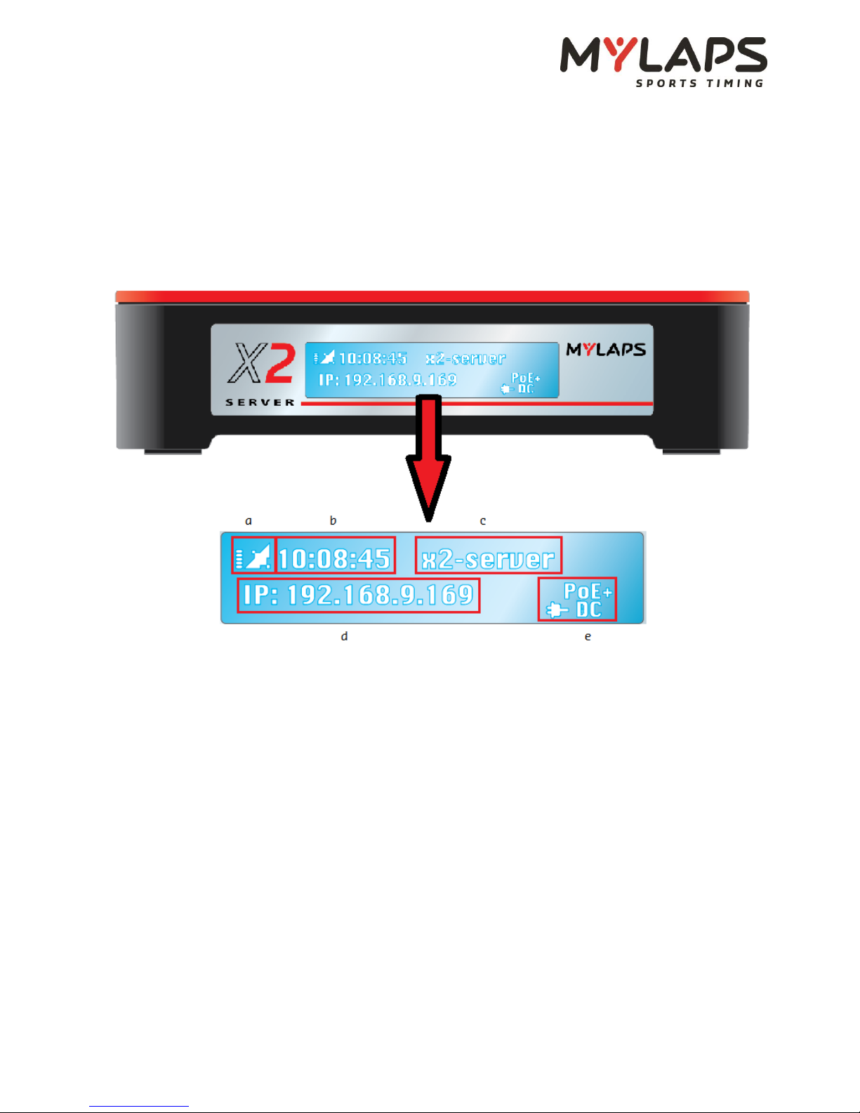
3.1 Server
Front Status panel
a) Blinks when GPS receiver is attached; lit when decoder is receiving UTC time from satellite
(signal strength is shown beside)
b) Time of day; UTC when synchronized to GPS
c) Server name
d) IP address
e) Display of the connected power source
X2 Club Installation Manual (Revision 3.02) Page 8 of 24
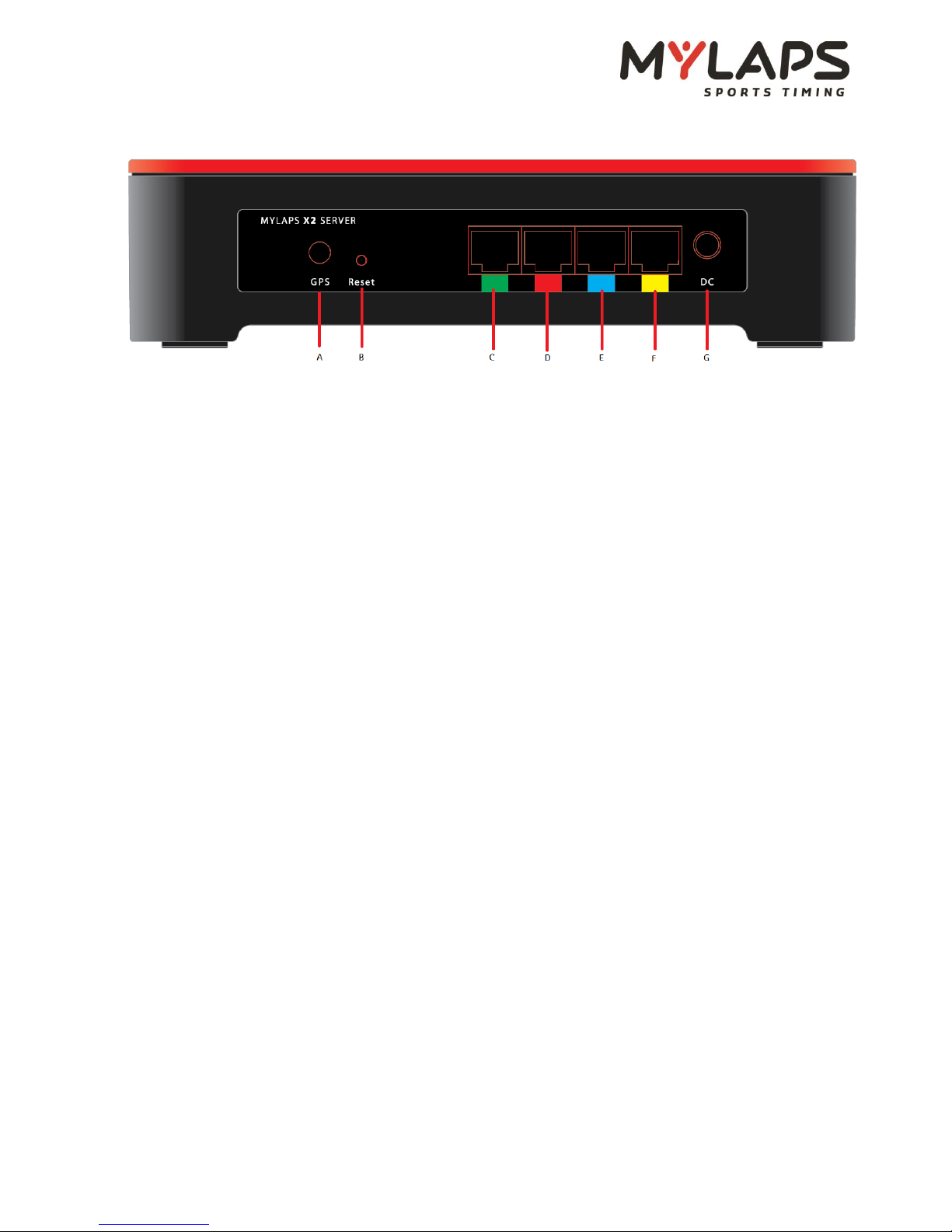
f) Rear Connections
A) Connection for GPS antenna cable
B) Reset button; to reset software to factory defaults; network settings will be set to DHCP
and the admin login account will be set to ‘admin’
C) Network connection between Server and Decoder or Timing network
D) Network connection between Server and Decoder or Timing network
E) Network connection between Server and Decoder or Timing network
F) Network connection between Server and Decoder or Timing network
G) Power connection for 12VDC power supply
Note: The LEDs on the UTP ports will show if a physical network connection is available.
Note: A PoE(+) switch can be used to power the Server over a single UTP port. In this case, any
of the four ports can be used to supply the power and the display will show a PoE or PoE+ icon.
Note: The four UTP ports are color-coded for examples on how the Server can be connected.
There are no dedicated ports and all the ports have the same configuration.
 Loading...