

Page 1

Contents
CHIPX DECODER INSTALLATION/OPERATION..........
1.1 Installation of the decoder...................................
1.2 Operating the decoder........................................
1.2.1 Noise level................................................
1.2.2 Signal Strength.........................................
1.2.3 Number of hits..........................................
1.2.4 Firmware update.......................................
1.3 Menu options explained......................................
1.3.1 MENU: General.........................................
1.3.2 MENU: Net................................................
1.3.3 MENU: Timing...........................................
1.3.4 MENU: Clock.............................................
1.3.5 MENU: Mylaps live.....................................
Appendices
APPENDIX A - FAQs.........................................................
APPENDIX B - EC AND FCC REGULATIONS.........................
APPENDIX C - TECHNICAL SPECIFICATIONS......................
GUARANTEES & WARRANTIES...........................................
Figures
Figure 1.1 System overview..............................................
Figure 1.2 Connections of the decoder...............................
Figure 1.3 Status display...................................................
Figure 1.4 Decoder with status display...............................
Figure 1.4 Menu...............................................................
3
4
5
5
5
5
6
6
9
10
10
11
11
13
15
16
17
3
4
6
7
8
1
Page 2

3
Contact Information
AMB i.t. Europe AMB i.t. America
Amsterdam Atlanta
The Netherlands USA
Tel: +31 23 529 1893 Tel: +1 678 816 4000
E-mail: E-mail:
support-eur@amb-it.com support-us@amb-it.com
AMB i.t. Asia AMB i.t. Australia
Tokyo Sydney
Japan Australia
Tel: +81 352754600 Tel: +61 2 9546 2606
Email: Email:
support-asia@amb-it.com support-aus@amb-it.com
www.amb-it.com
All rights reserved
Copyright © 2006 AMB i.t.
This publication has been written with great care. However,
the manufacturer cannot be held responsible, either for any
errors occurring in this publication or for their consequences.
This publication is to be used for the standard model of the
product of the type given on the cover page.
AMB i.t. Manual: ChipX Decoder/1.2
2
Page 3
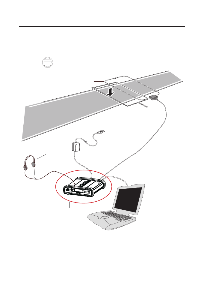
1: Decoder Installation/Operation
Transponder
Detec
tion loop
Powe
r
Headphone
Decoder
Computer
Figure 1.1 System overview
3
Page 4
5
1.1 Installation of the decoder
a)
b)
c)
d)
e)
The decoder is a precision instrument. Therefore please
handle it with care and keep the decoder out of direct sunlight
and avoid high humidity. Take special precautions in case of
thunderstorms by disconnecting all cables (coax, Ethernet
and mains) from the decoder. Nearby lightning strikes can
damage the decoder when these cables are connected.
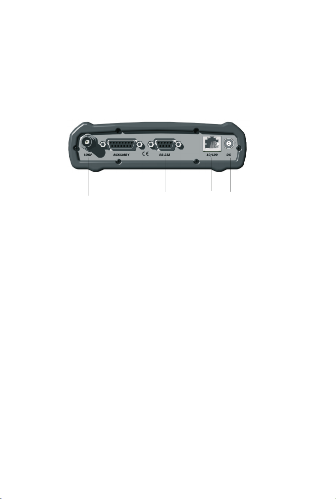
Figure 1.2 Connections of the decoder
How to connect
a) The detection loop: Connect the supplied 75 Ohm double-
shielded coax cable to the decoder.
b) The auxiliary port: This port can be used to connect a
photocell, external start pulse or a sync pulse. For more
information on how to connect these devices, contact your
nearest AMB i.t. ofce.
c) The serial port: This port can be used to connect the
decoder with the computer with a RS232 cable.
d) The network: Connect the network cable between the
decoder and the network connection port of the computer.
e) Power: Connect the 12 VDC adapter to the decoder and
mains. Since a power interruption will result in a failure
of the timing and scoring system, connecting the 12 VDC
adapter to mains through a UPS (Uninterruptible Power
Supply) is recommended.
f) The headphone: Connect it on the front side of the
decoder. A beep will sound for every passing transponder,
which provides an easy check for proper operation of the
decoder and the transponders on the track.
4
Page 5

1.2 Operating the decoder
The decoder is not equipped with an on/off switch, therefore
connecting the decoder to the mains will switch it on and will
enable timing of transponder passings after approximately 15
seconds. With each detection of a transponder, a beep will
sound in the headphone and received transponder information
is shown on the decoder display.
1.2.1 Noise level
The decoder determines the average background noise. The
noise (and signal strength) has a range of 0 to 255 points.
Noise level, as shown by the AMB i.t. timing software and
also on the decoder screen, should best not exceed 40 points.
If the noise level is higher, the received transponder signal
strength should be 60 points above noise level to ensure
proper functioning of the system. So if the transponder
received signal strength is 120 points, the noise should not
exceed 60 points.
1.2.2 Signal strength
Transponder signal strength, as shown by the AMB i.t. timing
software, should preferably be above 100 points and should at
least be 60 points higher than the indicated background noise.
The closer a transponder is to the track the higher the signal
strength. A higher transponder signal strength gives a higher
immunity against outside interference.
1.2.3 Number of hits
The number of hits, as shown by the AMB i.t. timing software,
is an indication of the number of repeated transponder signal
receipts during a passing. Hit-rate varies with the speed of a
passing transponder. Slower passings yield higher hit counts.
The minimum number of hits should not be below 10 points.
5
Page 6
7
1.2.4 Firmware update
Our products are in continuous evolution, for new
functionalities and small changes you can check our website
for a decoder rmware update. Please go to
http://support.amb-it.com and follow the instructions.
1.3 Menu options explained
On the front of the decoder, you will nd an information
display, designed to show and change the decoder settings.
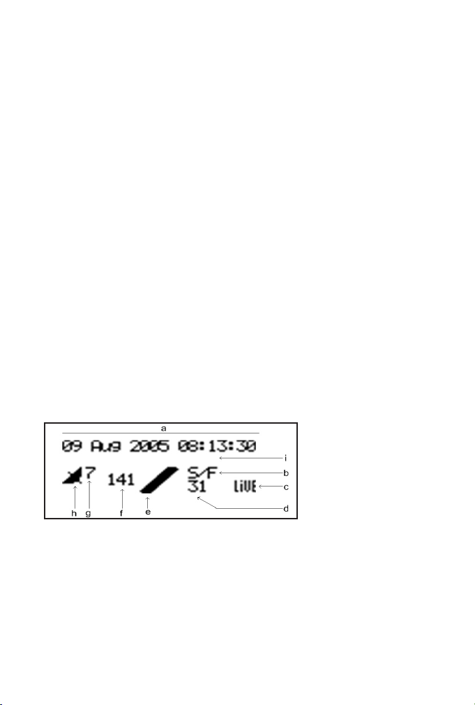
The status screen will show the following information:
- a: Decoder date/time, UTC when synchronized to GPS
- b: Timeline name
- c: Blinks when connecting to Mylaps Live, steady
when connected to Mylaps Live
- d: Background noise indication
- e: Indication that hits are received, remains black
when a transponder is being received by the loop.
- f: Strength of last received transponder
- g: Number of received GPS satelites
- h: Blinks when GPS receiver attached, steady when
decoder is locked to UTC time
- i: Message line
Figure 1.3: Status display.
By clicking on the Acknowledge button once, you will nd the
IP address of the decoder. By clicking this button twice, you
will nd the Ethernet Address/Serial number ( see 1.3.2.), by
clicking it three times, it will show the version and type of the
decoder, and by clicking it 4 times it will show the number of
passings stored in the ash memory.
6
Page 7
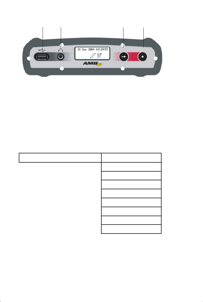
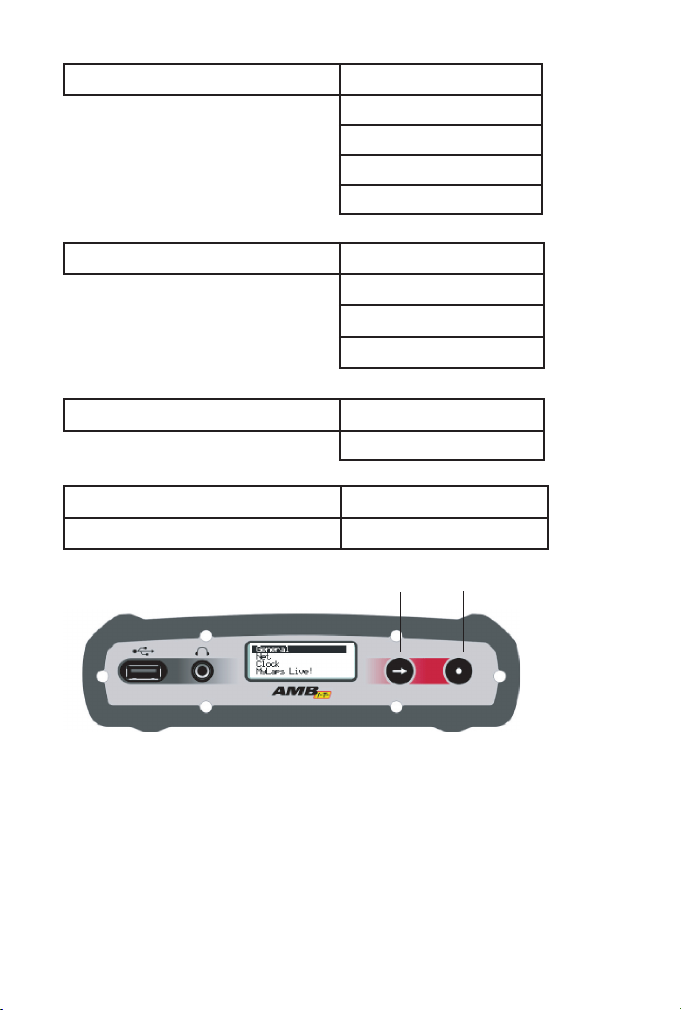
Figure 1.4: Decoder with status display.
USB
Headphones
Select button Acknowledge button
By clicking on the Select and Acknowledge buttons you can
choose which information you want to see on the display.
Detailed information of the menu options will be given on the
following pages.
By clicking on the select button you will nd a main menu
menu with different subjects :
General
Clear passings
Timeline
Beep
Loop trigger
First contact
Protocol RS232
Contrast
Factory defaults
Firmware
7
Page 8
9
Net
Select button Acknowledge button
Automatic
IP address
Subnet mask
Gateway
DNS
Timing
Clock
Mylaps live
Figure 1.5: Menu
Sport
Photo holdofff
ext. start holdoff
Sync holdoff
Date
Time
Active
Activation code
You can navigate between the menu items with the Select
button and you can choose a menu with the Acknowledge
button. Please note that you can go one step back by
selecting << and clicking the Acknowledge button.
8
Page 9

1.3.1 MENU: General
Within the general menu you can choose/see:
- Clear passings: clears the passings in the ash
memory.
- Timeline: description of the loop name.
Occasionally needed for the timing software.
- Beep: to choose the tone of the beep.
- Loop trigger: optional for future developments.
- First contact: when switched on the decoder will
send a record without a time stamp a soon as the
transponder is detected. This is intended to allow TV
graphics applications to already display a name, while
the passing time is not known yet (works with P3
protocol only).
- Protocol RS232: This is used to select the protocol
on the RS232 interface. There are 3 options:
Enhanced:
This protocol is here only for compatibility reasons.
Not all features are available via this protocol.
P3:
If you are a software developer this is the preferred
protocol to use. This protocol is also used for software
like ‘Racewave’ and ‘Orbits’.
Remote:
Allows the host computer to select the protocol by
using a command.
- Contrast: contrast of the display.
Here you can adjust the contrast settings.
- Factory defaults: reset to the factory defaults.
You can reset the settings of the decoder to the initial
settings.
- Firmware: software running inside the decoder
When you update the rmware in your decoder,
the decoder will retain the current version of the
rmware. With the switch rmware option you are
always able to revert back to the previous version.
9
Page 10

11
1.3.2 MENU: Net
Please leave the decoder in the automatic menu if you are not
familiar with network basics.
Within the Net menu you can choose/see:
- Automatic: to automatically determine the IP
address of the decoder.
If your decoder is placed in a network and you select
automatic “on” the decoder will rst try via the DHCP
server (DHCP = Dynamic Host Conguration Protocol)
to get an IP address which is in the range of the
network. Please note that it can take around 60 sec.
to obtain the settings via DHCP. If a DHCP server is
not found, the decoder will use an IP address via
APIPA (Automatic Private IP Addressing)
- IP address: IP address of your decoder
An identier for a computer or device on a TCP/IP
network.
- Subnet mask: A mask used to determine what
subnet an IP address belongs to.
- Gateway: A node on a network that serves as an
entrance to another network.
- DNS: Short for Domain Name System (or Service or
Server), an Internet service that translates domain
names into IP addresses.
Gateway and DNS are both used to set up the
decoder for Mylaps live.
1.3.3 MENU: Timing
Within the timing menu you can chooose/see:
- Sports:
There are many parameters which may inuence
timing performance. With the sport setting the
decoder uses some pre-dened parameters optimized
for a certain type of sport / transponder placement.
10
Page 11

Sport Loopwidth Transponder placement
Ice skating 50cm / 1.7ft Strap around ankle
Inline skating 60cm / 2ft Strap around ankle
Cycling 60cm / 2ft Vertically mounted to the bike
Other 60cm / 2ft
Note : Use ‘other’ if there is no exact match for sport and
transponder placement.
- Photo holdoff,
External start holdoff
Sync holdoff
This is the time in milliseconds the decoder will wait
before accepting a new pulse via one of those inputs.
1.3.4 MENU: Clock
Within the Clock menu you can see/change:
- Date: date settings
Here you can change the date
- Time: time settings
Here you can change the time of day
1.3.5 MENU: Mylaps live
MyLaps Live provides AMB transponder users and race fans
with live race information from circuits that use AMB i.t.
hardware around the world. It is your live global score board,
bringing you up-to-date real time results whenever and
wherever the action is.
11
Page 12

13
Within the Mylaps live menu you can see/change:
- Active: to put all passings directly on the live results
website or not.
- Activation code: a unique code which should be
used for registering on MyLaps Practice website
www.mylaps.com/practice. Please visit
www.mylaps.com for more information about nding
all your race results online.
Note : For using mylaps live you need a functioning internet
connection. Also the DNS server and gateway setting have to
be correctly congured (see menu ‘network’).
12
Page 13

Appendix A : FAQs
A1: Transponder is not being detected
A few of the transponders are not being detected.
If this is the case, the problem is most likely related to the
individual transponder or the positioning of the transponder.
- Check the mounting position of the transponder, for
more information check your transponder manual.
None of the transponders are being detected.
If this is the case, the problem is most likely related to the
detection loop, decoder, timing computer or cabling. Please
take the following steps:
- Check if a beep is heard in the headphone, or of
the loop in the display changes to black during a
transponder passing. If this is working, but nothing
appears on the computer screen, check the cabling
between the decoder and the computer.
- Check the coax cable by measuring the resistance
(with multimeter) between the centre pin and the
outside of the BNC connector. The reading should be
approximately 150 kOhm after 30 seconds. If not, the
coax has to be replaced.
- Check the loop wire by cutting the loop wires from
the connection box and measuring the resistance
between the loop wires in the track. The reading
should be approximately 220 Ohm. If this is not the
case, the loop has to be replaced. When
(re)connecting the loopwires to the connection box
please solder with proper connections (for more
information please check your system installation
manual).
13
Page 14

15
A2: Noise level
What if my background noise is higher than 40 points?
An increased background noise is an indication of a higher
interference level picked up by the system. Every ve seconds
a background noise measurement is performed by the
decoder and sent to the computer. The noise level should be
as low as possible, but as long as the received signal from the
transponders is 60 points higher then the noise level detection
will be reliable. If the noise level is higher than 70 there is
most likely something wrong with the installation.
Possible causes of high background noise levels:
- When the detection loop is damaged, a uctuation
in noise level will be noticeable, especially in wet
conditions. If this is the case, please check the
loop wire and coax for cuts or breakage.
- Electrical equipment too close (<3 m) to the loop or
coax cable.
- Using a generator with a poor ground connection
- Use of DC/AC converter for AC power.
- Poor connections between the detection loop and the
coax cable.
- BNC connector incorrectly tted to the coax cable.
- Poor ground connection of the AC power. If this is
the case, ground the decoder by connecting the
outside the BNC connectors on the decoder to a piece
of metal (copper rod or tube) that goes into the
ground.
A3: Signal strength
What if the received signal strength is below 100
points?
- If the signal strength is lower than 100 points, please
check the position of the transponder.
- If the signal strength is uctuating heavily in
combination with high noise levels, check the quality
of the loop installation and coax cables.
14
Page 15

Appendix B: EC and FCC Regulations
CE information:
This device complies with the EMC directive 89/336/EEC. A
copy of the declaration of conformity can be obtained at:
AMB i.t. BV
Zuiderhoutlaan 4
2012 PJ Haarlem
The Netherlands
FCC information:
This equipment complies with part 15 of the FCC rules.
Operation is subject to the following two conditions: (1) This
equipment may not cause harmful interference, and (2) this
equipment must accept any interference received, including
interference that may cause undesired operation.
15
Page 16

17
Appendix C: Technical Specications
Dimensions
Weight
Decoder Clock stability
Decoder Timimg Resolution 0.001 s
Time of day clock stability
(decoder off)
Time of day clock stability
(decoder on)
Time of day clock resolution 1 sec.
Time of day clock
synchronisation
Max. track width max. 20 m / 66 ft
Operating temperature range 0 - 50 C / 32 - 122 F
Humidity range 10 % to 90 % relative
Operating voltage range 10 to 14.4 V, typical 12V
Power consumption max. 600 mA @ 12V, typical 250 mA
Interfaces
Network connection DHCP client, APIPA, Static IP
Aux. Power 5 VDC, max 150 mA
Aux. Output
Aux. Inputs 3x Opto coupled 5-12 VDC / 5-15 mA
180 x 160 x 45 mm /
7 x 6.3 x 1.8 inch
720 g / 1.6 lb
0.5 ppm
+/- 25 ppm
+/- 0.5 ppm
via GPS receiver to UTC
(AMB part nr. 00017)
RS232, 9600 baud, 8 bits, 1 stopbit
10/100 BaseT
USB A
Opto coupled closing contact max 50
mA switched
Specications are subject to change without notice.
16
Page 17

Guarantees & Warranties
AMB i.t. guarantees that, for a period of twelve months from the date of
dispatch, decoders manufactured or sold by AMB i.t. with defects caused by
faulty materials and/or workmanship and/or design, will be repaired. If repair
is not possible or economical for AMB i.t., AMB i.t. has the choice to refund
the purchase price of these goods or to deliver new goods. AMB i.t.’s liability
shall be strictly limited to replacing, repairing or issuing credits at its option
for any goods returned within twelve months from the date of dispatch. AMB
i.t. shall not be liable for incidental or consequential damages including, but
not limited to costs of removal and reinstallation of goods, loss of goodwill,
loss of prots or use. If the requirements set forth above and described
below are not complied with, the AMB i.t. warranty/guarantee shall not apply
and AMB i.t. shall be discharged from all liability arising from the supply of
defective goods.
EXCEPT AS EXPRESSLY PROVIDED IN THIS SECTION, AMB i.t. MAKES
NO REPRESENTATIONS OR WARRANTIES OF ANY KIND, NATURE OR
DESCRIPTION, EXPRESS OR IMPLIED, INCLUDING WITHOUT LIMITATION,
ANY WARRANTY OR MERCHANTABILITY, FITNESS OF THE GOODS FOR
ANY PARTICULAR PURPOSE, OR NONINFRINGEMENT, AND AMB i.t. HEREBY
DISCLAIMS THE SAME.
Remedies and damages
AMB i.t. shall not incur any liability under the above warranty unless:
a) AMB i.t. is promptly notied in writing upon discovery by
the customer that such goods do not conform to the
warranty and the appropriate invoice number and date of
purchase information is supplied;
b) The alleged defective goods are returned to AMB i.t.
carriage pre-paid;
c) Examination by AMB i.t. of goods shall conrm the
alleged defect exists and has not been caused by misuse, neglect,
method of storage, faulty installation, handling, or by alteration or
accident.
17
 Loading...