

Mygale M14-F4 FORD User Manual
MYGALE
Technopole
58470 Magny-Cours
France
Tel : +33 (0)3 86 21 86 21
Fax : +33 (0)3 86 21 86 22
Version: V1.2
MYGALE M14-F4 FORD
MSA FORMULA
USER MANUAL

MYGALE
Technopole - 58470 Magny-Cours - France
Tel : +33 (0)3 86 21 86 21
Fax : +33 (0)3 86 21 86 22
2/58
0.0 CONTENT
0.0 CONTENT ....................................................................................................... 2
1.0 CAR VIEWS ..................................................................................................... 3
2.0 CAR SPECIFICATIONS ........................................................................................ 4
2.1 Dimensions .................................................................................................... 4
2.2 Weight ........................................................................................................ 4
2.3 Supplied Parts: Partners ..................................................................................... 5
3.0 SET UP AND OPTIONS ........................................................................................ 6
3.1 Geometry information (in baseline set-up) .................................................................. 6
3.2 Set Up Adjustment ........................................................................................... 7
3.3 Kinematics – Graphical Representation ..................................................................... 18
3.4 Springs ....................................................................................................... 22
3.5 Dampers ...................................................................................................... 23
3.6 Anti-Roll Bars ............................................................................................... 25
3.7 Aero Set Up ................................................................................................. 27
3.8 Brake bias ................................................................................................... 29
3.9 Pedal box adjustment ....................................................................................... 30
3.10 Set-up sheet Baseline Proposal ........................................................................... 33
3.11 Ballast ...................................................................................................... 34
3.12 Paddle shift ................................................................................................ 35
3.13 Gear box ratios ............................................................................................ 36
3.14 Data acquisition ............................................................................................ 37
3.15 Brake pads ................................................................................................. 37
3.16 Steering system adjustments ............................................................................. 38
4.0 ASSEMBLY AND MAINTENANCE ............................................................................ 39
4.1 Engine ........................................................................................................ 39
4.2 Transmission ................................................................................................. 39
4.3 Steering System ............................................................................................. 40
4.4 Hub Assembly ................................................................................................ 42
4.5 Bottom Front Wishbones .................................................................................... 43
4.6 Wheel Cables ................................................................................................ 43
4.7 Heat protection .............................................................................................. 44
4.8 Brake line protection ........................................................................................ 44
4.9 Electricity .................................................................................................... 44
4.10 Wings ....................................................................................................... 44
4.11 Head restraint ............................................................................................. 45
4.12 Monocoque Chassis and Crash Boxes ...................................................................... 45
4.13 Bodywork repairs ........................................................................................... 45
4.14 Extractible seat cut for loom ............................................................................. 45
4.15 Fire extinguisher ........................................................................................... 46
4.16 Markings and holograms ................................................................................... 46
4.17 Screws ...................................................................................................... 46
4.18 Fuel system ................................................................................................. 47
4.19 Cooling system .............................................................................................. 48
4.20 Filling fluids ................................................................................................ 51
4.21 Accident data recorder .................................................................................... 52
4.22 Exploitation tools ........................................................................................... 52
5.0 ANNEXES ...................................................................................................... 56
5.1 Tightening torques (general) ................................................................................ 56
5.2 Tightening torques (F4 mounting): .......................................................................... 57
MYGALE
Technopole - 58470 Magny-Cours - France
Tel : +33 (0)3 86 21 86 21
Fax : +33 (0)3 86 21 86 22
3/58
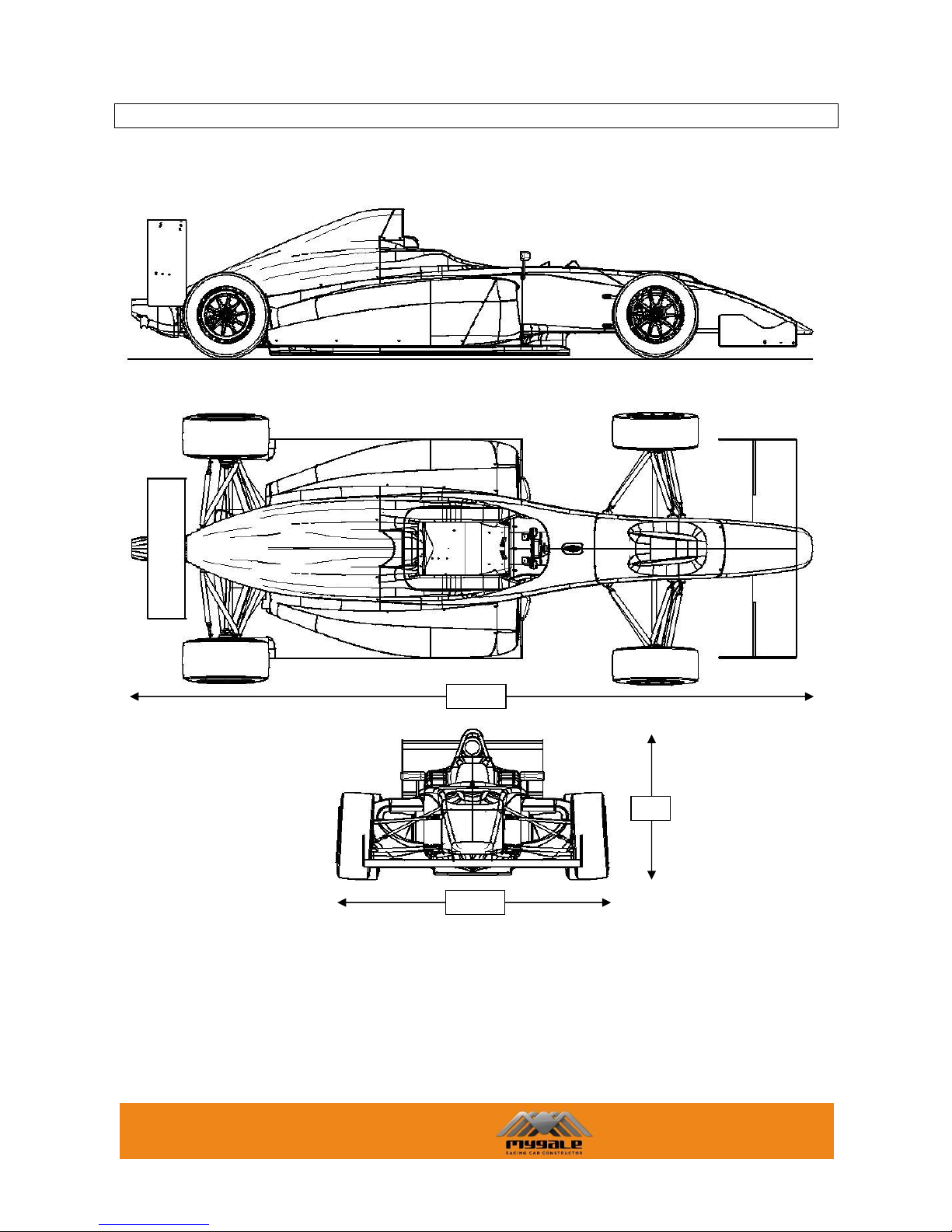
1.0 CAR VIEWS
1738
4341
958

MYGALE
Technopole - 58470 Magny-Cours - France
Tel : +33 (0)3 86 21 86 21
Fax : +33 (0)3 86 21 86 22
4/58
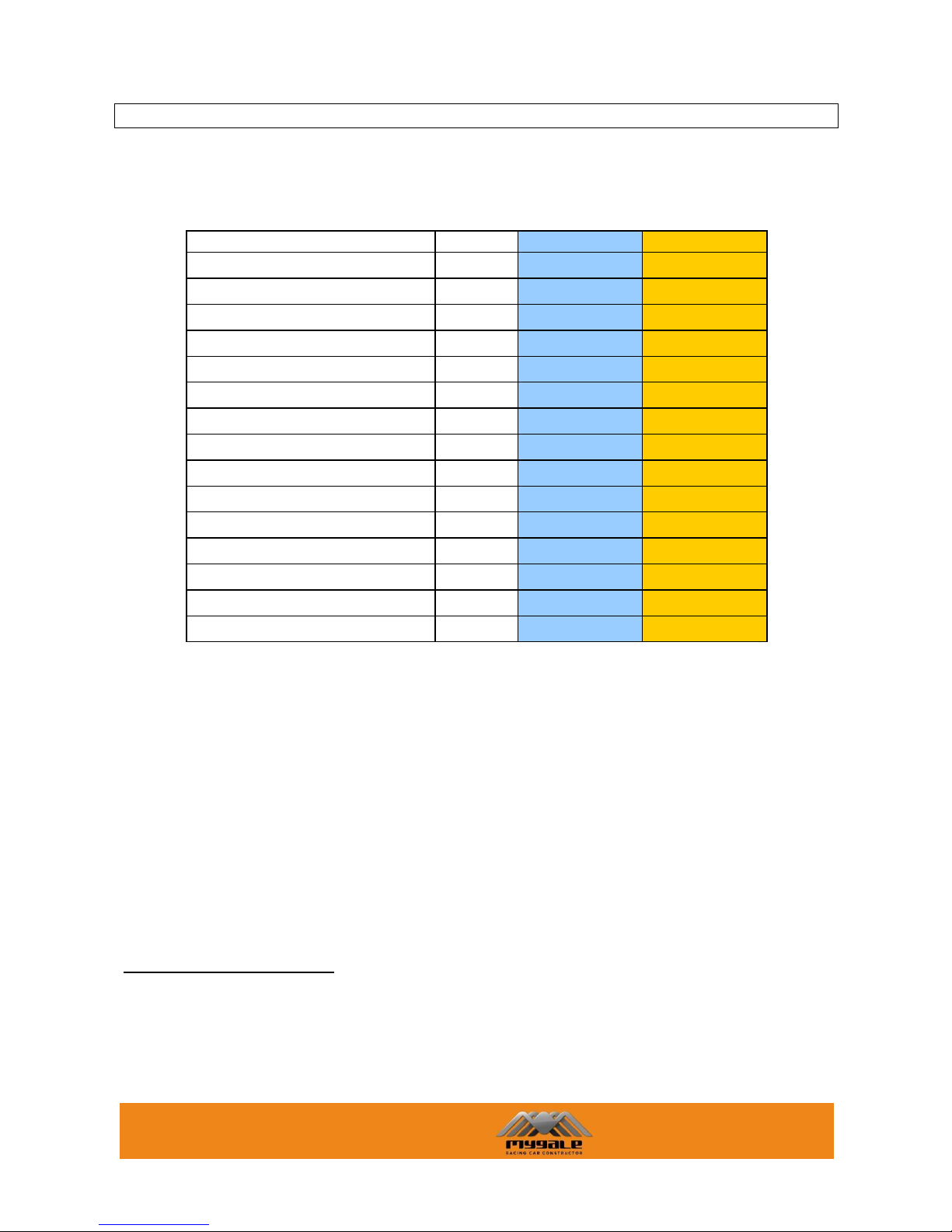
2.0 CAR SPECIFICATIONS
2.1 DIMENSIONS
Description
Reference Dimensions
Length
mm
4341
Height
mm
958
Front ride height
mm
20
Rear ride height
mm
30
Wheelbase
mm
2742
Front overhang
mm
1000
Rear overhang
mm
600
Front overall width
mm
1725 *
Rear overall width
mm
1715 *
Front track
mm
1493.5
Rear track
mm
1430.4
Front wing assy width
mm
1400
Rear wing assy width
mm
898
* depending tyres
2.2 WEIGHT
The minimum allowed weight is specified by sporting regulations of the championship.
The weight of the car should be adjusted by mean of appropriate ballast to ensure that the specified
minimum weight is reached with the driver at any time during the event.

MYGALE
Technopole - 58470 Magny-Cours - France
Tel : +33 (0)3 86 21 86 21
Fax : +33 (0)3 86 21 86 22
5/58
2.3 SUPPLIED PARTS: PARTNERS
Gearbox, driveshaft: Sadev
Steering rack: Titan
Springs, dampers: Sachs
Fuell cell, fuel pump: Premier Fuel
Brake pads: Ferrodo
Brake discs, callipers: Brembo
Extinguisher : OMP
Harness : TRS Motrosports
Rims : Team Dynamics
MYGALE
Technopole - 58470 Magny-Cours - France
Tel : +33 (0)3 86 21 86 21
Fax : +33 (0)3 86 21 86 22
6/58
3.0 SET UP AND OPTIONS
3.1 GEOMETRY INFORMATION (IN BASELINE SET-UP)
The standard set up of the car is:
dimension
FRONT
REAR
Ride Height
mm
24
37
Camber
deg
-3.3
-2.2
Toe
deg
0.00
0.00
Castor
deg
8.21
-22.81
Castor Offset (wheel centre)
mm
5.64
---
Castor Offset (ground)
mm
31.23
---
King Pin
deg
15.46
---
King Pin Offset (wheel centre)
mm
69.1
---
King Pin Offset (ground)
mm
15.4
---
Damper-Spring / Wheel
ratio
0.68
0.71
Anti Roll Bar (deg) / Wheel
ratio
0.69
0.48
Anti Dive % 14.45
22.13
Ackermann
deg
19.9
---
Roll Center Z
mm
17.8
34.5
Mechanical Trail1
mm
30.87
---
1
Mechanical Trail
The perpendicular distance in side elevation between the steering axis and the centre of tyre contact.
It is considered positive when the steering axis is forward of the tyre contact centre and negative
when it is rearward.
MYGALE
Technopole - 58470 Magny-Cours - France
Tel : +33 (0)3 86 21 86 21
Fax : +33 (0)3 86 21 86 22
7/58
3.2 SET UP ADJUSTMENT
Values are theoretical, assembly dispersion is possible.
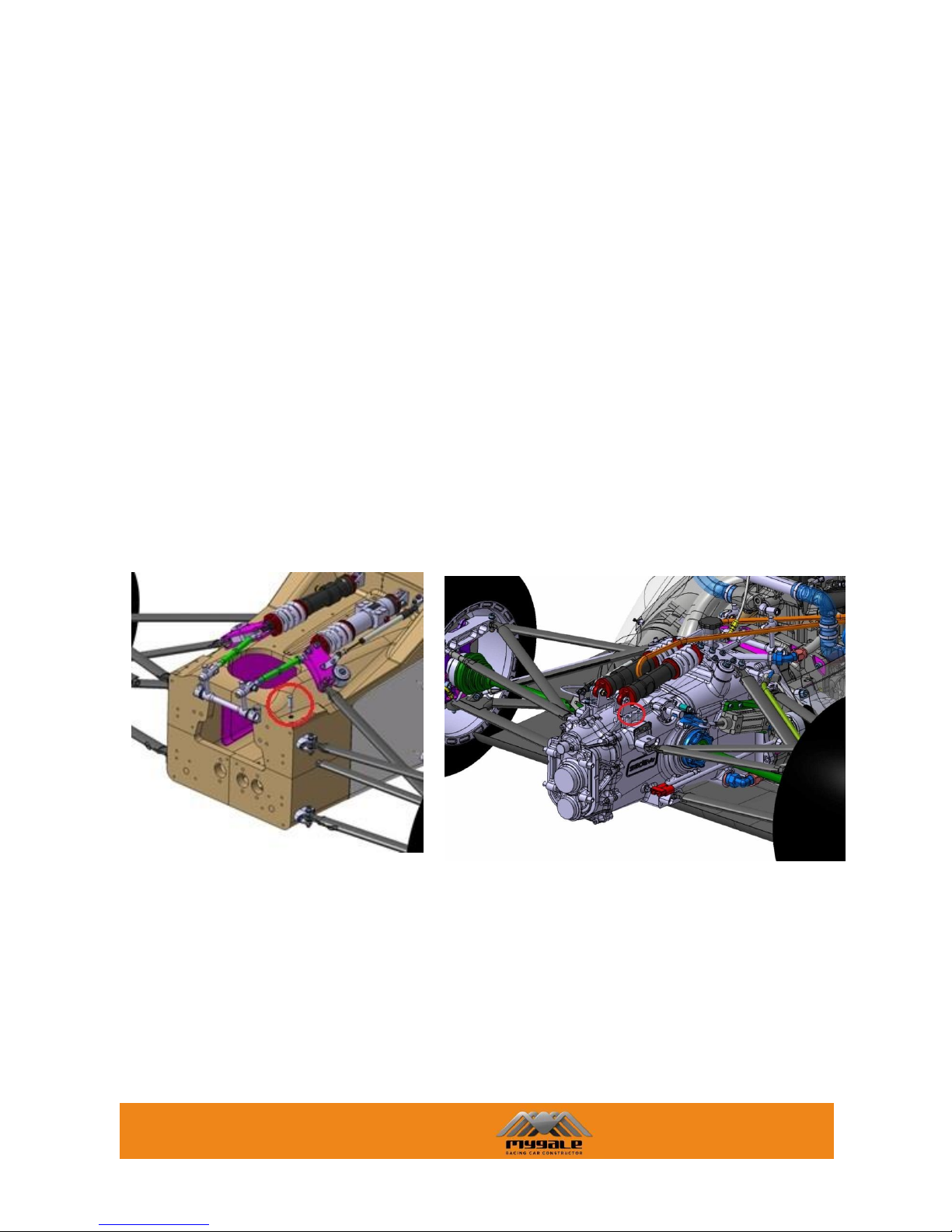
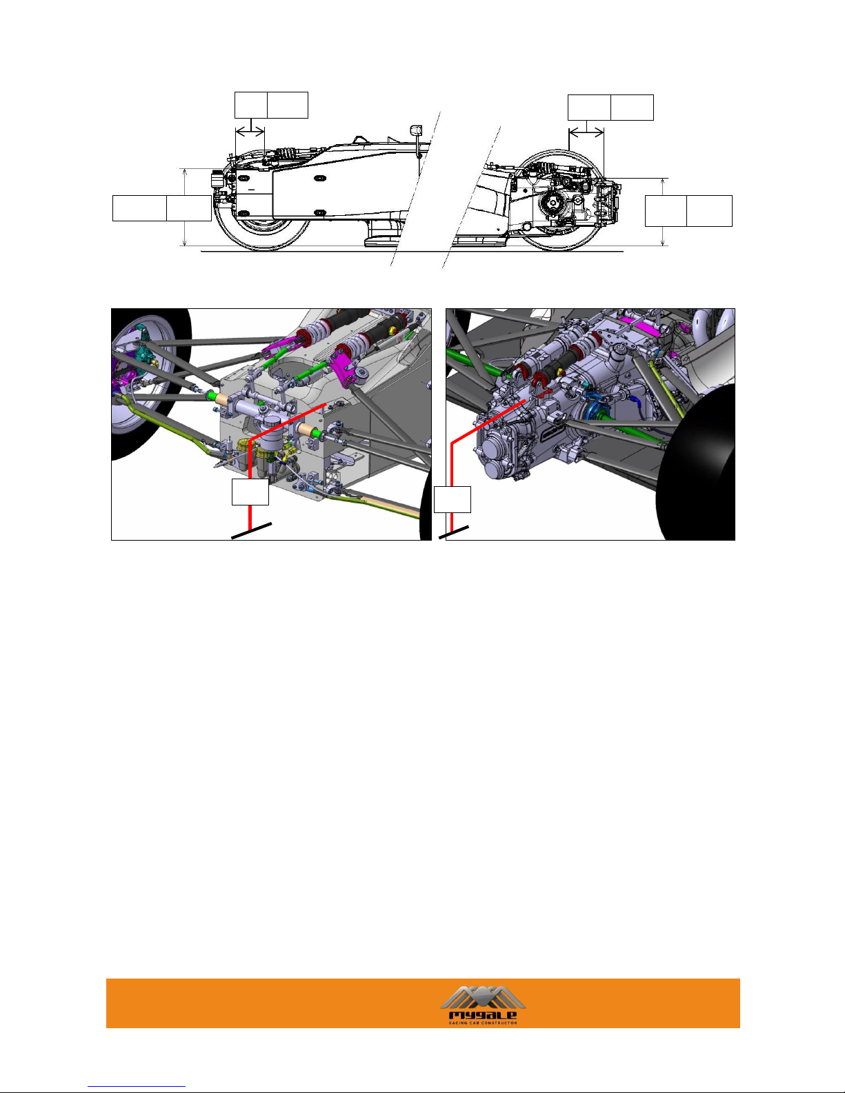
3.2.1 RIDE HEIGHT CHECK & ADJUSTMENT
The reference points for calculating the ride height are shown below.
The vehicle reference plane is the lower side of the wood floor. The skid block is below this. The
choice of ride height needs to take account of the skid block thickness which is a maximum of 5mm
below the reference plane (and minimum 2mm).
The diagrams refer to the dimensions from the chassis reference point to the reference plane.
At the front two ride height adjustment screws (F.41.35.001) must be fix on the two reference pads
which are machined into the upper surface of the monocoque and are accessible with the damper cover
removed.
At the rear the reference surfaces are machined pads on the gearbox upper surface, at the level of
the damper bracket and are accessible with the engine cover removed.
Front reference Rear reference
The front reference dimension A1 is 441mm.
The rear reference dimension A2 is 369mm.
MYGALE
Technopole - 58470 Magny-Cours - France
Tel : +33 (0)3 86 21 86 21
Fax : +33 (0)3 86 21 86 22
8/58
b
To set up front and rear ride height values at the level of the front and rear axle centre lines (H1 and
H2 respectively), use the following calculation:
X1 = A1*cos(α) - B1*sin(α) + H1
X2 = A2*cos(α) + B2*sin(α) + H2
(Dimensions in mm)
Where α is the car pitch angle, α = arcsin((H2-H1)/2741.6 in rad.
B1
165
369
A2
A1
441
B2
230
X1
X2
MYGALE
Technopole - 58470 Magny-Cours - France
Tel : +33 (0)3 86 21 86 21
Fax : +33 (0)3 86 21 86 22
9/58
Ride height adjustment:
Front:
Lengths (ball centre to ball centre) for a 20mm ride height: Pushrod 554.6mm.
1 face on the adjuster changes the ride height by 0.95mm.
1 turn on the adjuster changes the ride height by 5.70mm.
For 1mm ride height, 1/6 turn on the adjuster.
Rear:
Lengths (ball centre to ball centre) for a 30mm ride height: Pushrod 527.5mm.
1 face on the adjuster changes the ride height by 1.00mm.
1 turn on the adjuster changes the ride height by 6.00mm.
For 1mm ride height, 1/6 turn on the adjuster.
Front ride height adjustment
Lengthen adjuster to raise car.
Shorten adjuster to lower car
Rear ride height adjustment
Lengthen adjuster to raise car.
Shorten adjuster to lower car
MYGALE
Technopole - 58470 Magny-Cours - France
Tel : +33 (0)3 86 21 86 21
Fax : +33 (0)3 86 21 86 22
10/58
3.2.2 CASTOR CHECK & ADJUSTMENT
The castor angle is the angle, in side elevation, between the steering axis and the vertical. It is
considered positive when the steering axis is inclined rearward.
You can check the castor angle in the same way in the front and in the rear suspension. The castor
angle can be calculated as follows:
Measure the angle of the steering arm plane for the front (or the wishbone mount plane for the rear)
to the horizontal; this is the measured castor angle (MCA). Positive inclined down to rear, negative
inclined down to front. Calculate the true castor angle (TCA) as following:
Front Castor Angle
Rear Castor Angle
True castor angle
= MCA + 7.08°
= MCA - 25.41°
Base settings
8.21°
-22.81°
Base set up length, wishbone
ball centre to ball centre
556.4mm
578.9mm
The Castor angle influences the Castor Offset, the Mechanical Trail and therefore the force to turn
the wheel.
Castor Offset, (mm)
The distance in side elevation between the point where the steering axis intersects the ground, and
the centre of tyre contact. The offset is considered positive when the intersection point is forward of
the tyre contact centre and negative when it is rearward. (Base setting: FRT=31.23mm)
Mechanical Trail, (mm)
The perpendicular distance in side elevation between the steering axis and the centre of tyre contact.
It is considered positive when the steering axis is forward of the tyre contact centre and negative
when it is rearward. (Base setting: FRT=30.87mm)
The Castor Offset is along the ground plane while the Mechanical Trail is perpendicular to the steering
axis.
MCA
TCA
MCA
TCA
Car direction
Horizontal and
vertical lines
MYGALE
Technopole - 58470 Magny-Cours - France
Tel : +33 (0)3 86 21 86 21
Fax : +33 (0)3 86 21 86 22
11/58
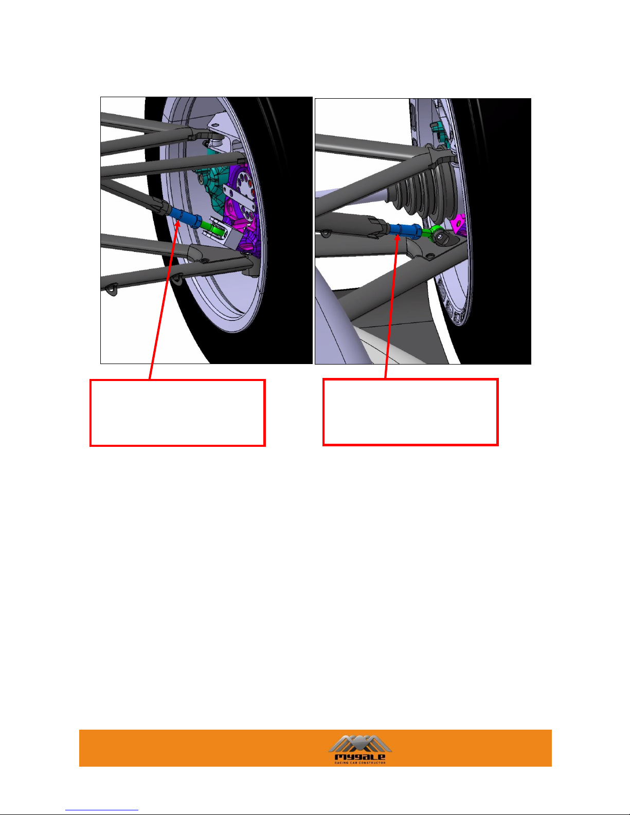
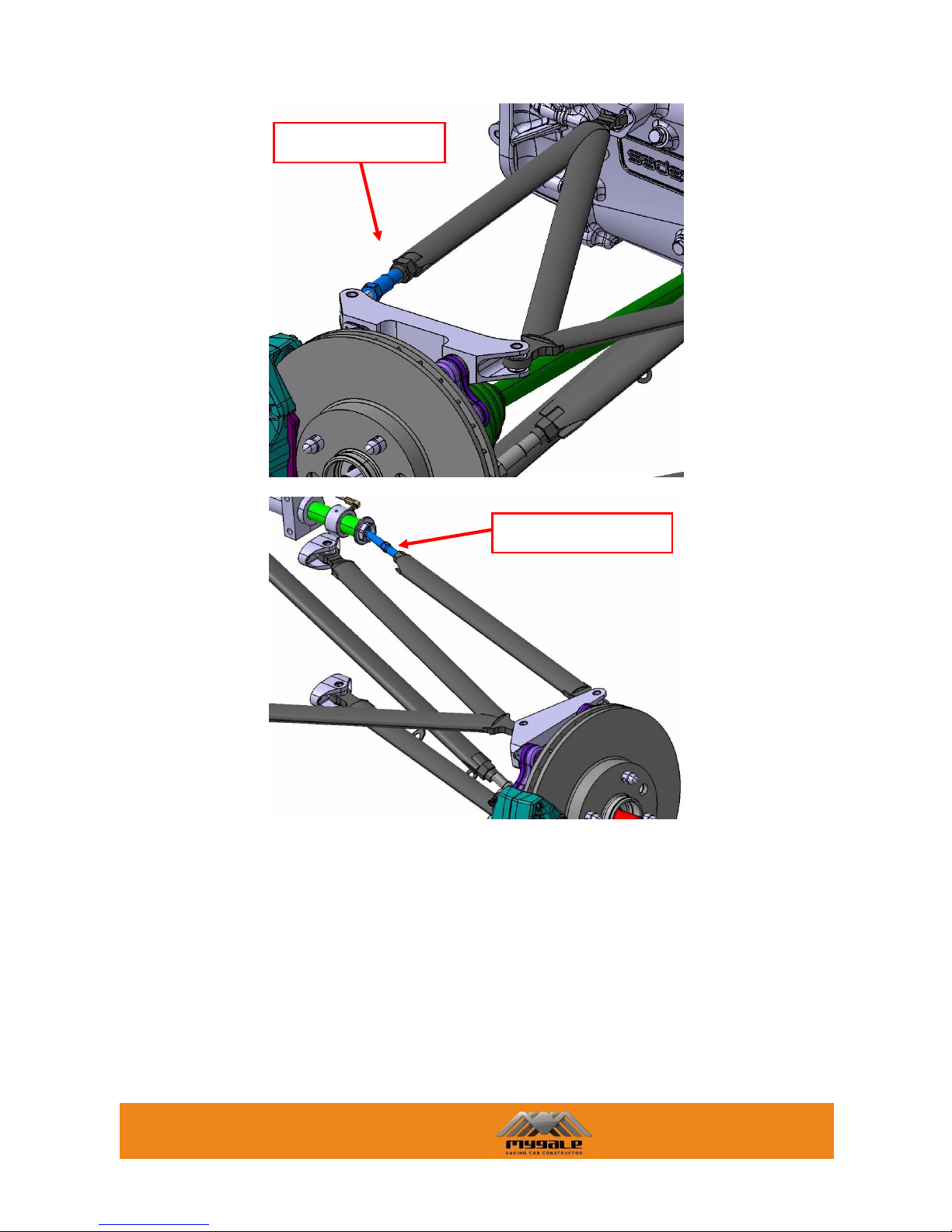
Castor adjustment:
Adjust the castor angle with the rod end bearings as shown in the following pictures:
Front castor adjustment
Rear castor adjustment
MYGALE
Technopole - 58470 Magny-Cours - France
Tel : +33 (0)3 86 21 86 21
Fax : +33 (0)3 86 21 86 22
12/58
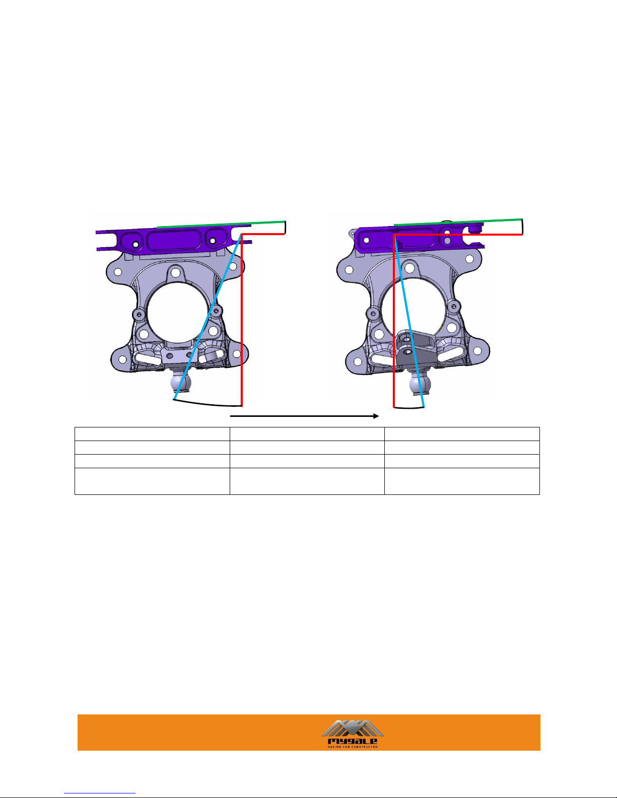
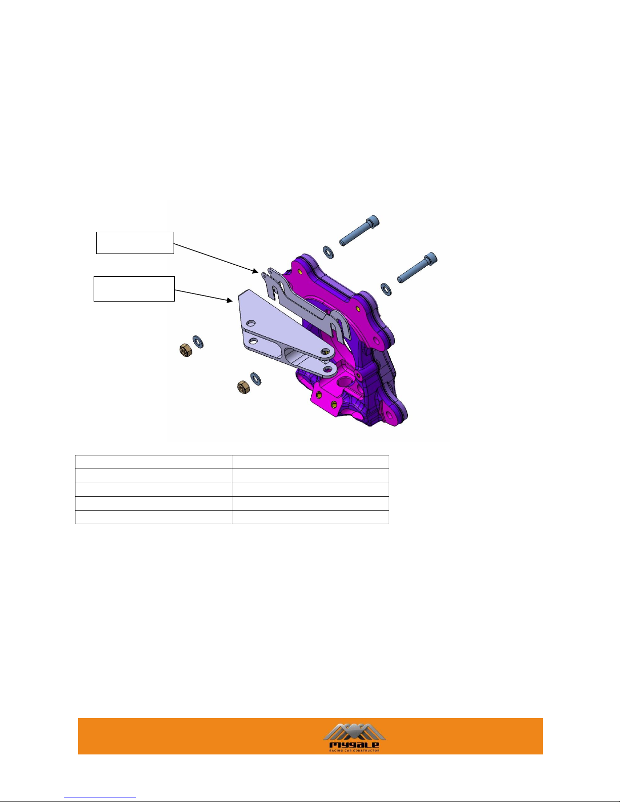
3.2.3 CAMBER ADJUSTMENT
The Camber Angle is the inclination of the wheel plane to the vertical. It is considered positive when
the wheel leans outward at the top and negative when it leans inward.
The Camber can be adjusted by releasing the fixing bolts and adding or removing shims between the
steering arm and the upright. A change of shim has no influence on the toe setting.
Front (Rear similar)
Available shims:
Part Number
Description
F.41.14.055.A
Camber shim 1 mm
F.41.14.056.A
Camber shim 1.5 mm
F.41.14.057.A
Camber shim 2 mm
F.41.14.058.A
Camber shim 4 mm
Front
Recommended base setting: -3,3°, 2mm of shim
Adjustment: 0.325°/mm
1.5mm for 0.5°
Rear
Recommended base setting: -2.2°, 4.5mm of shim (2mm + 1.5mm+1mm)
Adjustment: 0.300°/mm
1.5mm for 0.5°
Steering arm
Camber shim
MYGALE
Technopole - 58470 Magny-Cours - France
Tel : +33 (0)3 86 21 86 21
Fax : +33 (0)3 86 21 86 22
13/58
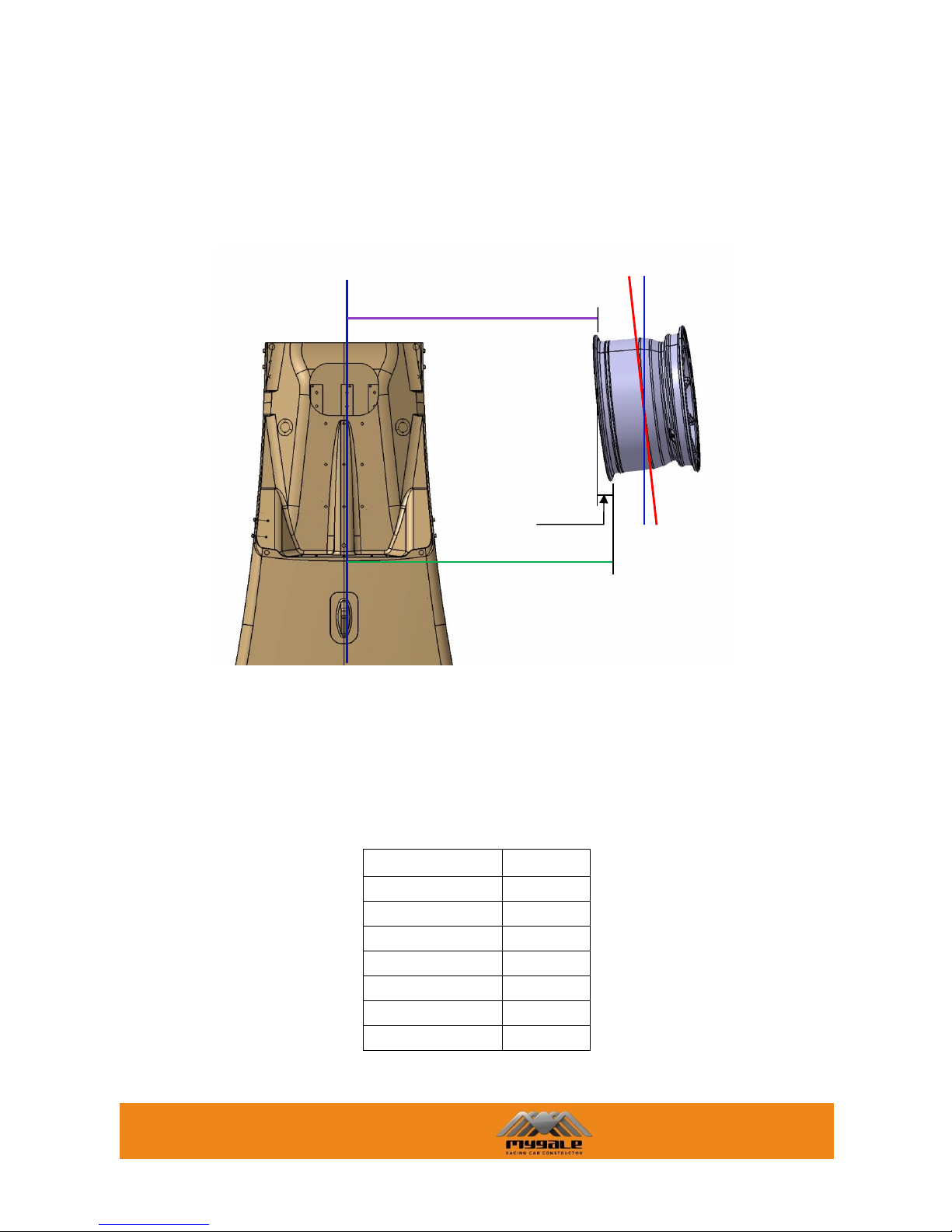
3.2.4 TOE CHECK & ADJUSTMENT
The toe angle is the angle between a longitudinal axis of the vehicle and the line of intersection of the
wheel plane and the road surface. The wheel is ”toed-in” if the forward portion of the wheel is turned
towards a central longitudinal axis of the vehicle, and “toed-out” if turned away.
Checking the distance between the wheel forward and rearward points in the front suspension is
possible to measure the Toe.
The Toe can be measured with the following formula:
Toe = B/2 – A/2
The correlation between degrees and the value B/2-A/2 is :
B/2-A/2 (mm)
Toe (deg)
18 3 12 2 6 1 0 0 -6
-1
-12
-2
-18
-3
In this table, negative toe corresponds to “toe out”, positive toe corresponds to “toe In”. The Toe
angle can be adjusted with the track rod.
A/2
semi forward track
B/2
semi rearward track
T.A. = Toe
To
MYGALE
Technopole - 58470 Magny-Cours - France
Tel : +33 (0)3 86 21 86 21
Fax : +33 (0)3 86 21 86 22
14/58
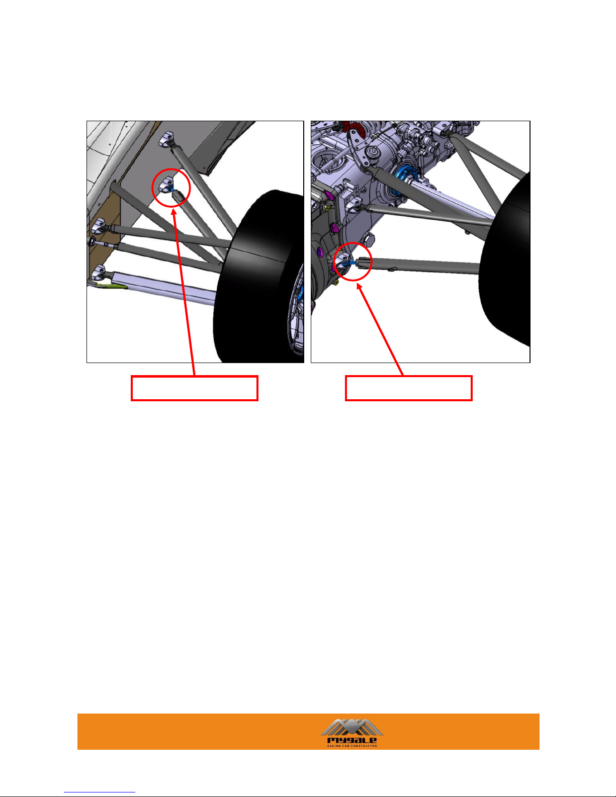
Base starting set up lengths for toe adjustment (ball centre to ball centre)
Front trackrod assembly: 474.9mm for (toe 0° and 0mm)
±1 turn on the bearing = ±3.84mm
±1 face turn on the bearing = ±0.64mm
For 1mm toe: 1.6 faces bearing
Rear trackrod assembly: 478.7mm for (toe 0° and 0mm)
±1 turn on the adjuster = ±4.70mm
±1 face turn on the adjuster = ±0.43mm
For 1mm toe: 2.4 faces adjuster
Rear toe adjustment
Front toe adjustment
MYGALE
Technopole - 58470 Magny-Cours - France
Tel : +33 (0)3 86 21 86 21
Fax : +33 (0)3 86 21 86 22
15/58
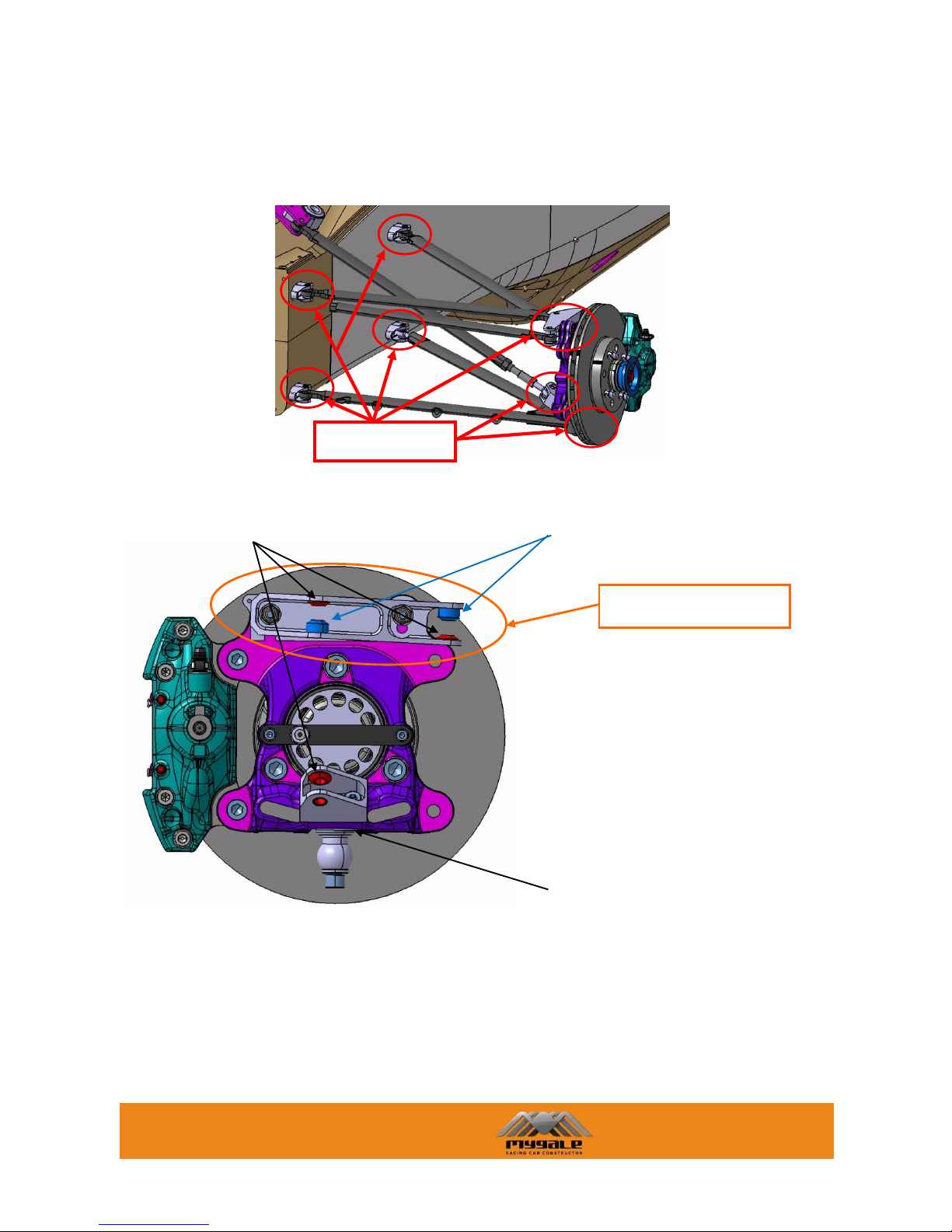
3.2.5 SUSPENSION POINTS
Front suspension points
The following picture shows the mandatory position of the front upright points:
Fixation points
Steering arm position
Ref. F.41.14.064.B (x2)
Ref. F.41.14.063.B (x4)
Spacer Ref. F.41.14.097.A
MYGALE
Technopole - 58470 Magny-Cours - France
Tel : +33 (0)3 86 21 86 21
Fax : +33 (0)3 86 21 86 22
16/58
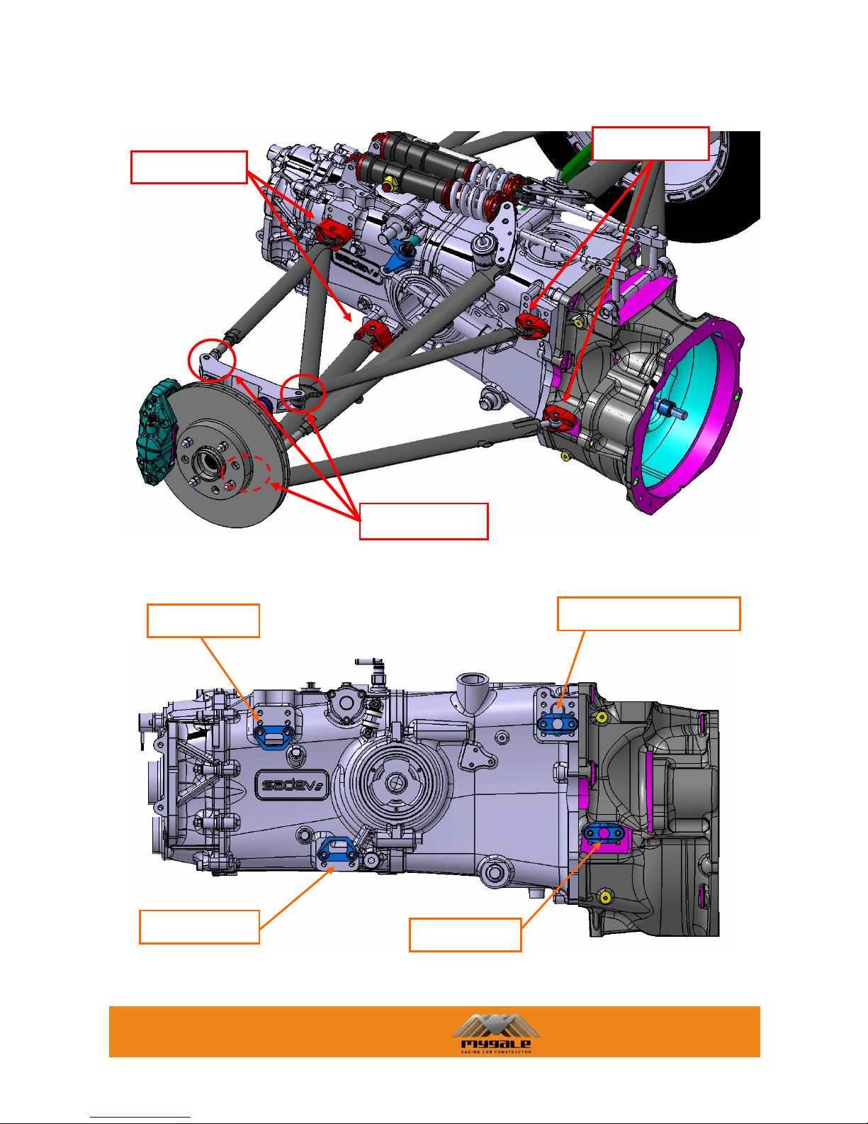
Rear suspension points
The following picture shows the mandatory position of the rear wishbone brackets:
2nd hole from the bottom
Lower position
Upper position
Middle position
Fixation points
Fixation points
Fixation points
MYGALE
Technopole - 58470 Magny-Cours - France
Tel : +33 (0)3 86 21 86 21
Fax : +33 (0)3 86 21 86 22
17/58
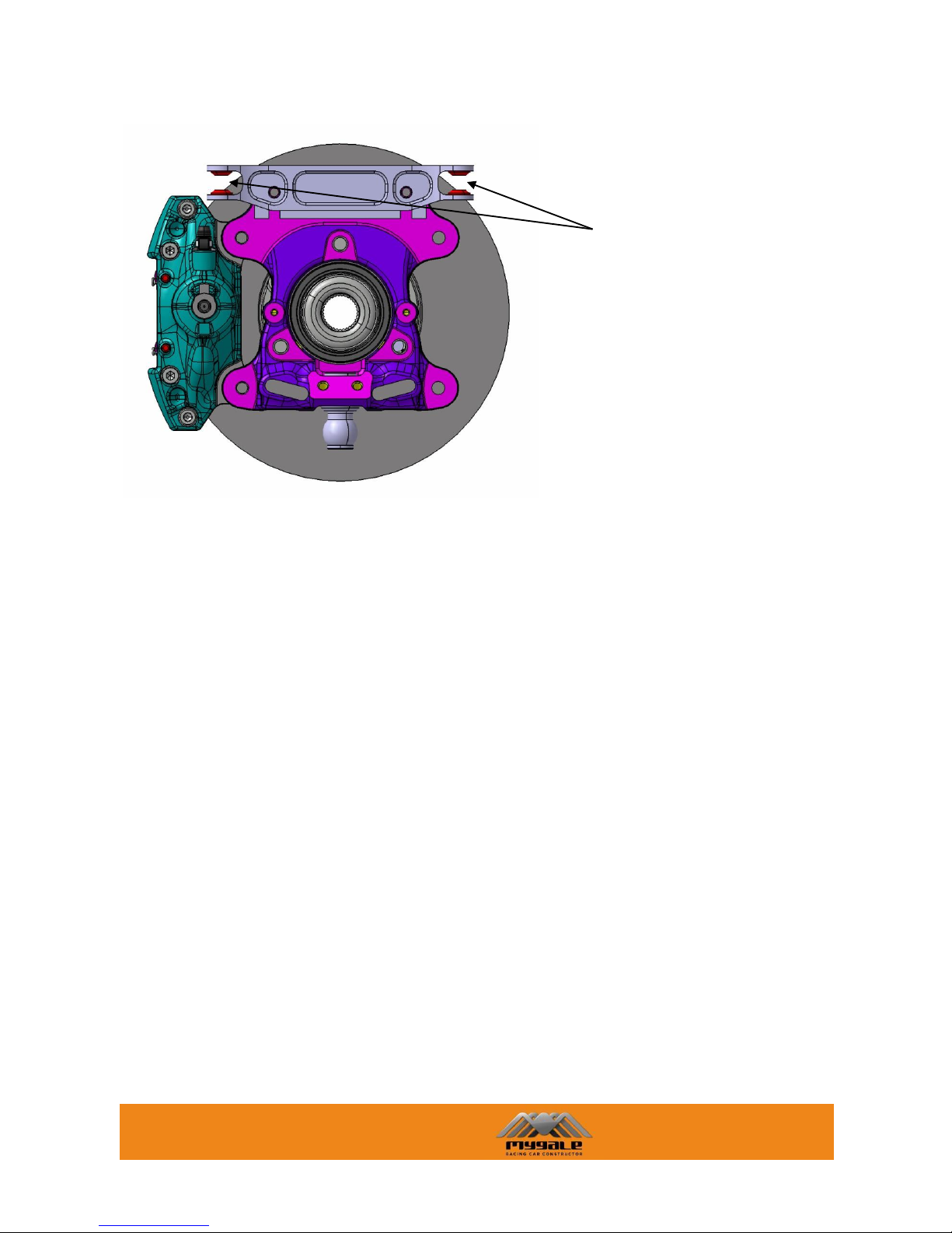
The following picture shows the mandatory position of the rear upright points:
Ref. F.41.14.063.B (x4)

MYGALE
Technopole - 58470 Magny-Cours - France
Tel : +33 (0)3 86 21 86 21
Fax : +33 (0)3 86 21 86 22
18/58
3.3 KINEMATICS – GRAPHICAL REPRESENTATION
All the following graphs represent the kinematics in standard setup.
 Loading...