

Myford ML7, ML7-R, Super 7 User Manual

Gearboxes supplied for
subsequent fitting only Far M
L7 lathes prior to K125240 and
Super 7 lathes prior to
SK124461 instead of screws
267 (paragraphs 9, 11S and
11M also parts list) use 1/2"
B.S.F. x 3/4". If far your
machine you need the 1/4"
B.S.F. screws, return the metric
screws to us for exchange.
No. 712V
QUICK CHANGE
GEARBOX
Nos, 1480 (ML7) and 1680 (ML7-R) and Super 7)
INSTRUCTIONS FOR
INSTALLATION AND OPERATION
WITH
PICTORIAL PARTS LIST
Myford Ltd, Wilmot Lane, Chilwell Road, Beeston, Nottingham NG9 I
ER Telephone: 01 15 925 4222 • Fax: 01 15 943 1299 email address:
Myford@btinternet.com
MYFORD QUICK CHANGE GEARBOX
CAUTION
IT IS OF THE UTMOST IMPORTANCE THAT THE WHOLE
GEARBOX AND TRANSMISSION MECHANISM SHALL ROTATE
MISALIGNMENT OF LEADSCREW OR TIGHTNESS IN ANY OF
THE BEARINGS (GEAR TRAIN-GEARBOX-OR LEADSCREW) WILL
IMPOSE HEAVY LOADS ON THE GEAR TRAIN AND MAY LEAD TO
SERIOUS DAMAGE.
THE CUTTING OF UNUSUALLY COARSE PITCHES IN EXCESS
OF .125"), EXERTS EXCESSIVE PRESSURE ON THE LEADSCREW
AND GEAR MECHANISMS. GREAT CARE SHOULD BE TAKEN SO
AS TO MINIMISE THE LOADS IMPOSED.
N.B. When changing to the slotted quadrant (page 6 fig. 5) or
back to the standard quadrant (page 3 fig. 2) it may be
necessary to reset the anchor pin No. 03 (see page 15
paragraph 22) in order to line up the driven gear on the
first stud with the driver on the tumbler stud.
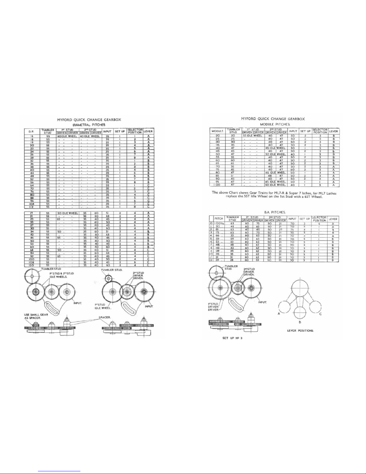
The chart for diametral pitches has been included for the
benefit of users wishing to cut wor ms t o mes h wi th
wormwheels whose pitch is expressed as D.P. The table of
module pitches has been included for the s am e rea so n.
Wh e r e a s diametral pitch is the ratio of the number of teeth
to the pitch diameter (in inches), module is the ratio of the
pitch diameter (in millimetres) to the number of teeth.
Before operating the lathe, remove the level plug
(at the right-hand end of the boxy, and fill to
just s ho rt o f plug level with 80025, Esso Febis
K68 oil. Replenish the oil ba th oc ca si ona ll y. A t
lon
g
intervals, flush with 800127, Esso Nuto
The tumbler reverse gear pins and quadrant gear
pins should be lubricated frequently. Occasional
application of the oil gun to the oil nipples on the
gear box will be sufficient.
Illustrations not bindin
g
in detail.
MYFORD QUICK CHANGE
OPERATION
The Myford Quick Change Gear Box permits instant
selection of 48 Englis h threads and feeds without the necessity for
setting-up gear trains. A conversion set is available fo r cutting
Metric , B.A. , and thou sands of oth er odd pitches, using ordinary
changewheels in conjunction with the gear box.
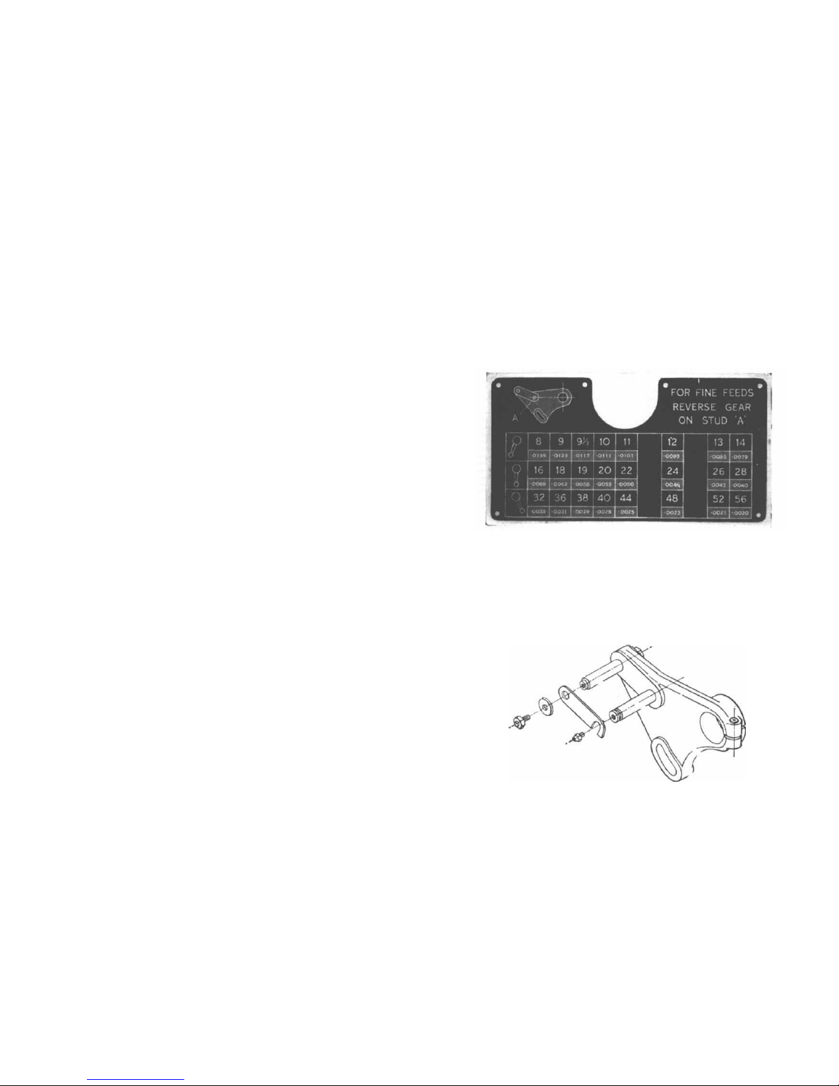
Fig. 1. Gear Box Chart showing English threads and feeds.
Reference to the gear box chart Fig. 1, will show that all
the commonly used English pitches are covered. In view
of this the gear pins on the normal quadrant (as supplied
with the gear box), are placed at fixed centres. This permits
the advantage of mounting the driving train of gears on pins
which are considerably greater in diameter, and more robust
than the movable type of changewheel stud.
Fig. 2. Normal
SET UP No 1 SET UP No 2
Fig. 3. Chart showing Changewheel Trains for Diametral Threads. (The four diagrams on
pages 4 and 5 apply to Diametral, Module and B.A. Charts).
Fig. 4. Chart showing Changewheel Trains for Module and B.A. Threads. (The
four diagrams on pages 4 and 5 apply to Diametral, Module and B.A. Charts).
 Loading...