

MyFlyDream MFD AAT User Manual
MyFlyDream
Automatic Antenna Tracker
Manual
V 3.0
www.MyFlyDream.com
Notes
Thank you for purchasing the MyFlyDream Automatic Antenna Tracker (hereinafter
referred to as MFD AAT).
Please follow this manual to get familiar with the tracker and to operate it correctly.
The tracker is a precision mechanical and electronic device. Please read this
manual carefully to avoid damaging the device or hurting yourself and others.
The tracker is designed for use with RC-models only. Please use it in compliance
with applicable local laws. The reliability and accuracy of the tracking system
depend on a number of factors. A strong electromagnetic interference, bad GPS
status and other reasons may cause a bad tracking result. Please consider the risk
and take it yourself. Any loss or damage caused by the tracker system is not our
responsibility.
We reserve the right to continuously improve the product performance, so this
document is not necessarily in full compliance with the tracker you purchased. The
latest version of this document will be available at our website:
www.MyFlyDream.com
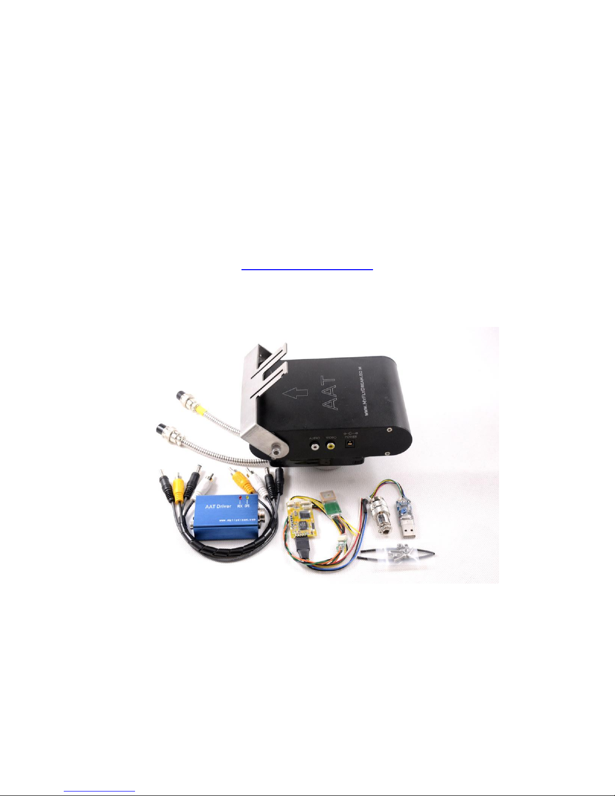
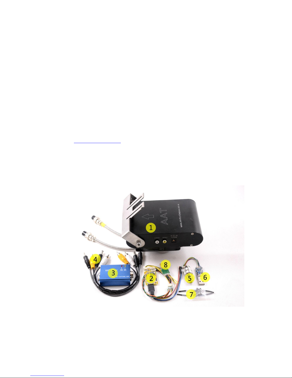
1. System Components
1. MyFlyDream Tracker
2. MyFlyDream TeleFlyOSD
3. MyFlyDream AATDriver
4. Cables connecting the AAT and your AV receiver
5. 7Pin Connector (for 12 channels version only)
6. USB Programmer (for firmware update)
7. Heat shrinkable tubes and M3x8mm stainless steel screws/nuts
8. Connector between the AAT and your AV receiver
2. Working Principle
In FPV flight, in order to get a better quality of video signal reception, we often wish to
use high-gain antenna. But any high-gain antenna is accompanied by a narrow effective angle.
MFD AAT is designed to solve the difficulty to keep the directional antenna pointed at the
target to ensure the best possible reception and transmission during FPV flight.
To form a complete system, you need to mount the TeleFlyOSD module on the plane. The
TeleFlyOSD reads data from the GPS on the plane, encodes and modulates the planes
coordinates and height information and transmits them back via a wireless audio channel
(usually the audio channel of the video transmission link is used).
The tracker forwards the audio signal received to the AATDriver. The AATDriver
demodulates and decodes the signal to obtain the plane position information. After
comparing with the original coordinates, it gets the current plane azimuth, distance and
height, etc. relative to the tracker. Then the AATDriver transmits the information to the
tracker that drives the internal servo to aim the directional antenna at the planes position.
3. Specifications
With a built-in high quality electrical slip ring, MFD AAT has a unrestrained, continuous
panning capability. There is also a built-in electronic compass which makes it as a
Plug-and-Play system without extra initialization.
Tracker:
Weight
905g
Size
165*107*40mm (Length*Wide*Height)
Input voltage
12V
Current consume(empty load)
100mA
Loading capacity
1KG
Tilt range
0~90 Degrees
Pan range
Unlimited (0~∞ Degrees)
Tilt speed
100 Degrees/s
Pan speed
200 Degrees/s
Spare signal channels
1~7
TeleFlyOSD:
Weight
(Not including the harness)
9g
Size
45 * 25 mm
Input voltage
7~20V (7~13V if connected with an
ExtensionBoard)
Current consume
100mA
AATDriver:
Weight
58g
Size
78*44*23mm (Length*Wide*Height)
Input voltage
12V
Current consume
100mA
Virtual GPS
Communication
baud rate
1200bps
*Virtual GPS:AATDriver can virtualize itself as a bluetooth
GPS module. It outputs the location information of the
plane with $GPGGA and $GPRMC command.
4. Connection and Set-up
1) Connecting TeleFlyOSD
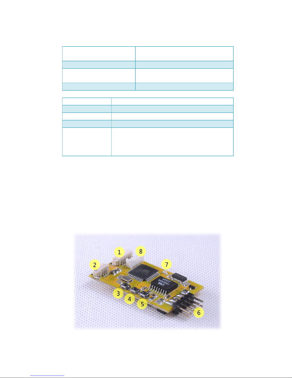
Introduction to TeleFlyOSD
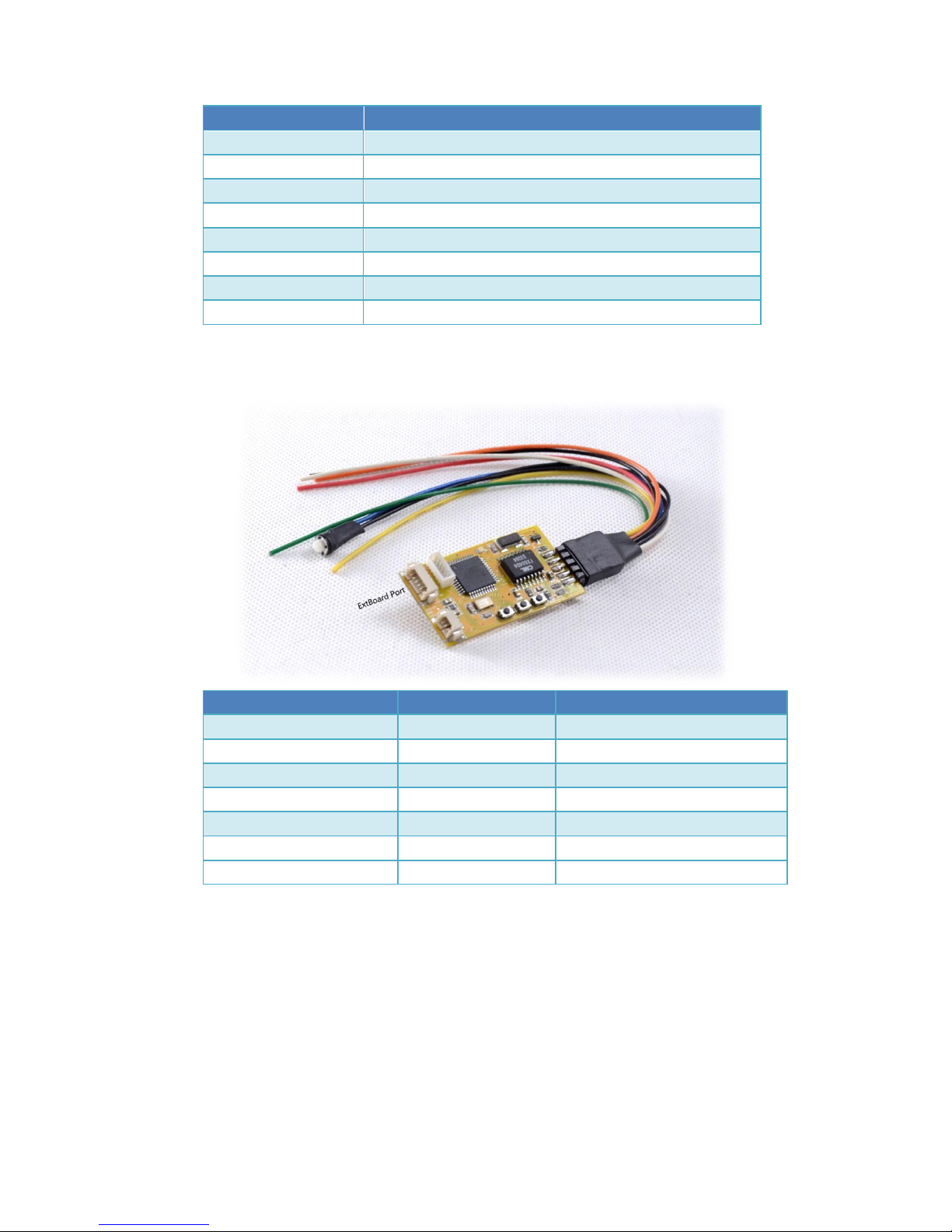
Part #
Name
1
Extension board port
2
OSD video signal port
3
UP button
4
SET button
5
DOWN button
6
Connecting pins
7
LED 8 Firmware upgrade socket
Wires color and function
Colour
Name
Remard
Red
Power
Power input
Black(3 wires)
GND
Ground
Blue
SetHome
Set the tracker position
Green
GPS Data
GPS Data
Orange
GPS Power
GPS Power supply(3.3V) *
White
Audio Out
Audio output to transmitter
Yellow
Video Out
OSD video output to transmitter
* Maximum current output: <200ma. Please make sure that your GPS current consumption
does not exceed these limits.
Connecting TeleFlyOSD
The TeleFlyOSD can either use a separate GPS or share a GPS with another
component (OSD, Autopilot).
Please refer to Connection Diagram A if a separate GPS is being used. In this

configuration, the TeleFlyOSD powers the GPS.
In the diagram, the operating voltage of GPS is assumed to be 3.3V. If your GPS needs
an operating voltage of 5V, refer to Appendix A.
Please refer to Connection Diagram B if a GPS is shared with another component
(OSD, Autopilot). In this example, the GPS and another OSD connect as usual for
power supply.
See Chapter 7 “OSD Functions” for specific OSD functions of TeleFlyOSD.

Connection Diagram A (power the GPS by TeleFlyOSD)
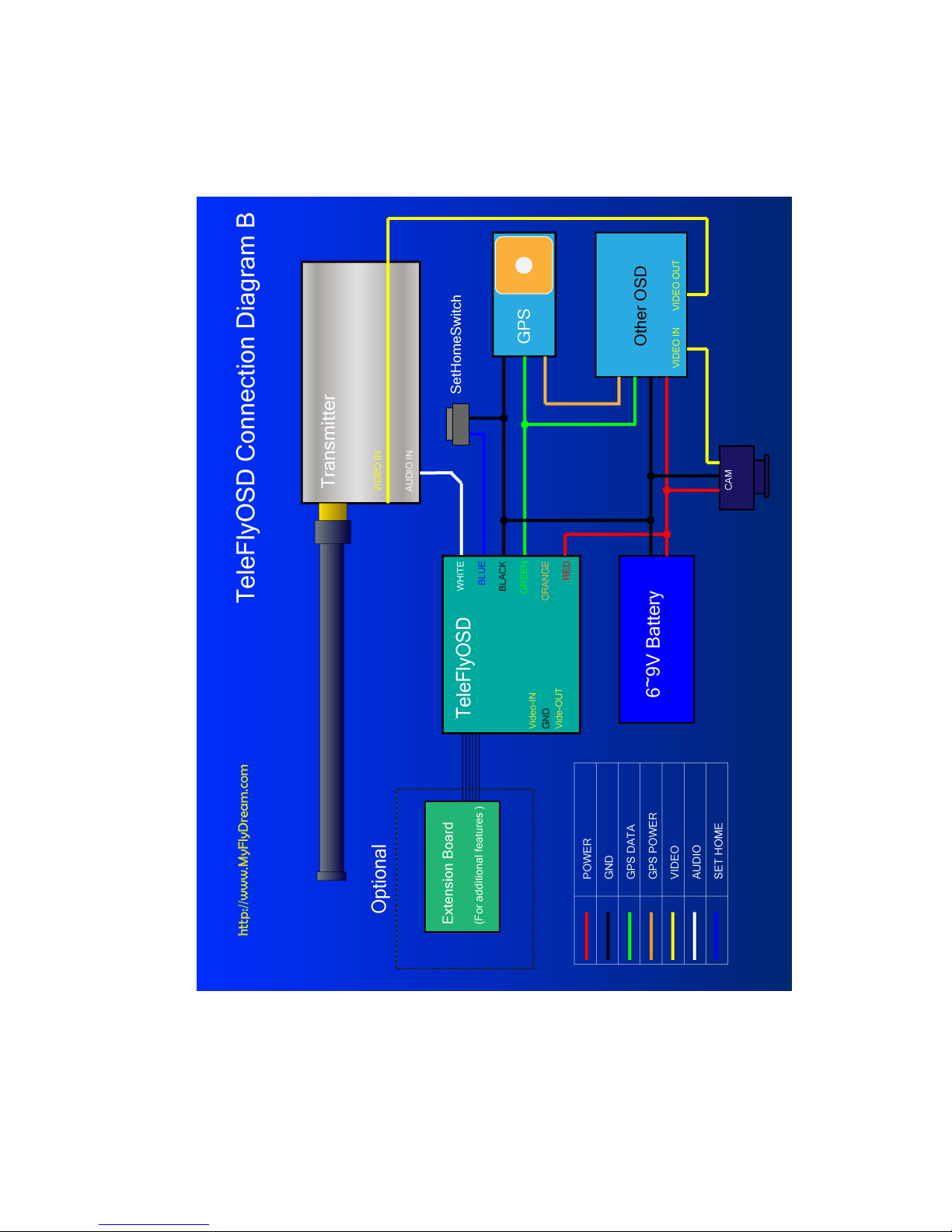
Connection Diagram B (share GPS with other OSD)
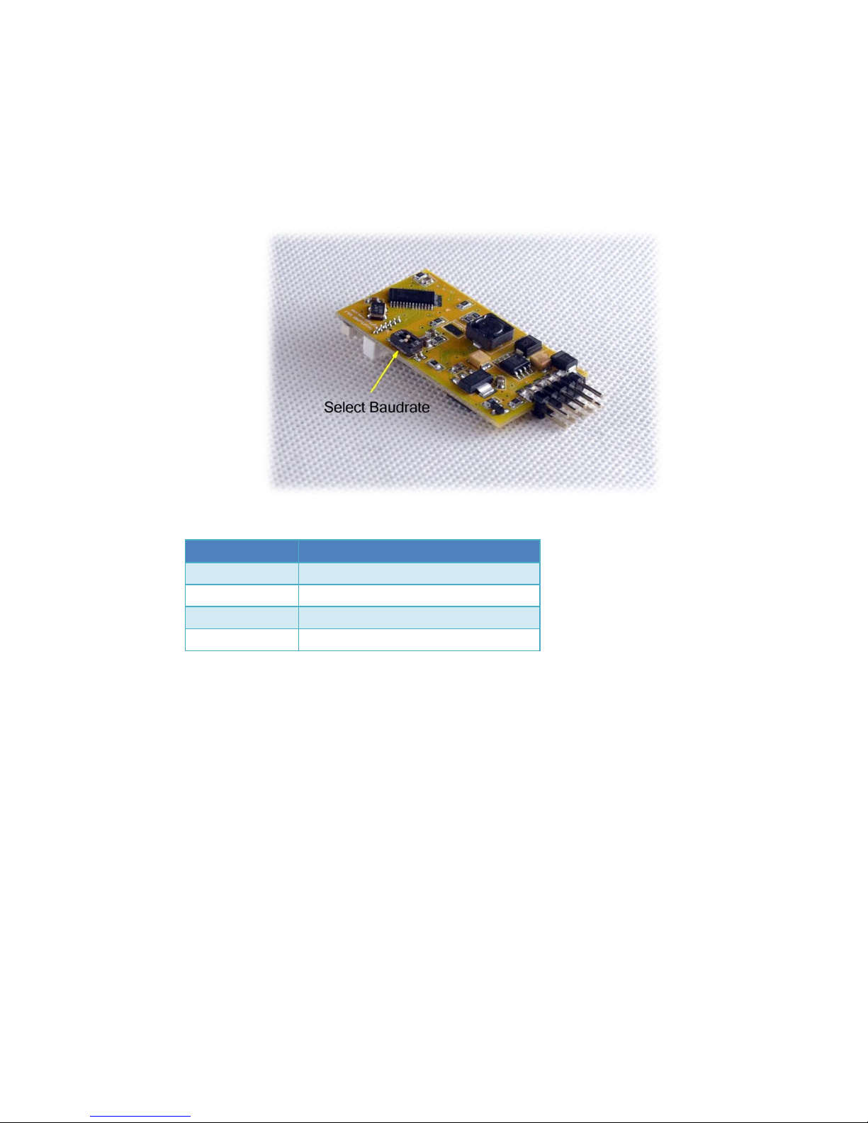
Selecting appropriate baudrate for TeleFlyOSD
Since the output data rate of different GPS may be different, it is necessary to set the
baudrate of the TeleFlyOSD communication port to match the GPS used. There is a
two-way DIP switch on the backside of the TeleFlyOSD module which is used to select
baudrates:
The arrow-indicated DIP switch in the figure has an ON mark above. There may be four
different baudrate combinations via setting of this switch:
DIP Status(1-2)
Communication Bardrate(bps)
OFF-OFF
115200
OFF-ON
38400 (Default)
ON-OFF
57600
ON-ON
9600
Power on after checking correct connection. The TeleFlyOSD LED will turn on. After
a few seconds, if the communication between TeleFlyOSD and GPS is working normally,
the LED will flash at half the GPS data update frequency. If the LED is lit continually,
check whether the GPS connection and baudrate setting are correct.

2). Mounting tracker and AATDriver
Please mount the antenna on the antenna handler of the tracker firmly. The image
transmission receiver is suggested to be mounted on the antenna handler to avoid
electronmagnetic interference. Antenna cables tend to be stiff, continual bending due to the
movement of the tracker might damage it. Specific mounting methods should be designed
according to the actual situation. The following picture is for reference only.
Connect the AATDriver to the tracker and mount the tracker on the tripod. Do not ever
try to hold the tracker in hand to test it to avoid damage to the device and yourself. Three
cables lead from the tracker: black 5.5mm power plug, yellow video plug and white audio
plug. Connect the three cables to the corresponding jacks on your video transmission
receiver. Please note that the 5.5mm power plug is directly connected to the power supply of
the AATDriver. For example, if the power supply voltage for the AATDriver is 12V, the power
plug output is 12V, too. If the interface specifications or power supply voltage do not match
your image transmission receiver, you need some additional hardware like a step-up or
step-down regulator to connect them.
Finally, connect your monitor to the yellow RCA terminal of the AATDriver to view the
video signal.
 Loading...