

MYERS WHR, WHRH, WHRE, WHR-DS, WHR-SD L/D Installation And Servicing Instructions
...
WHR/WHRH
and WHRE
WASTE HANDLING
SUMP PUMPS
Installation and Servicing Instructions
for Myers WHR/WHRH and WHRE
Submersible Sump Pumps
Single & Three Phase Power
Single & Double Seal
SINGLE SEAL PUMPS
23833A201 (Rev. 6/09)
DOUBLE SEAL PUMPS
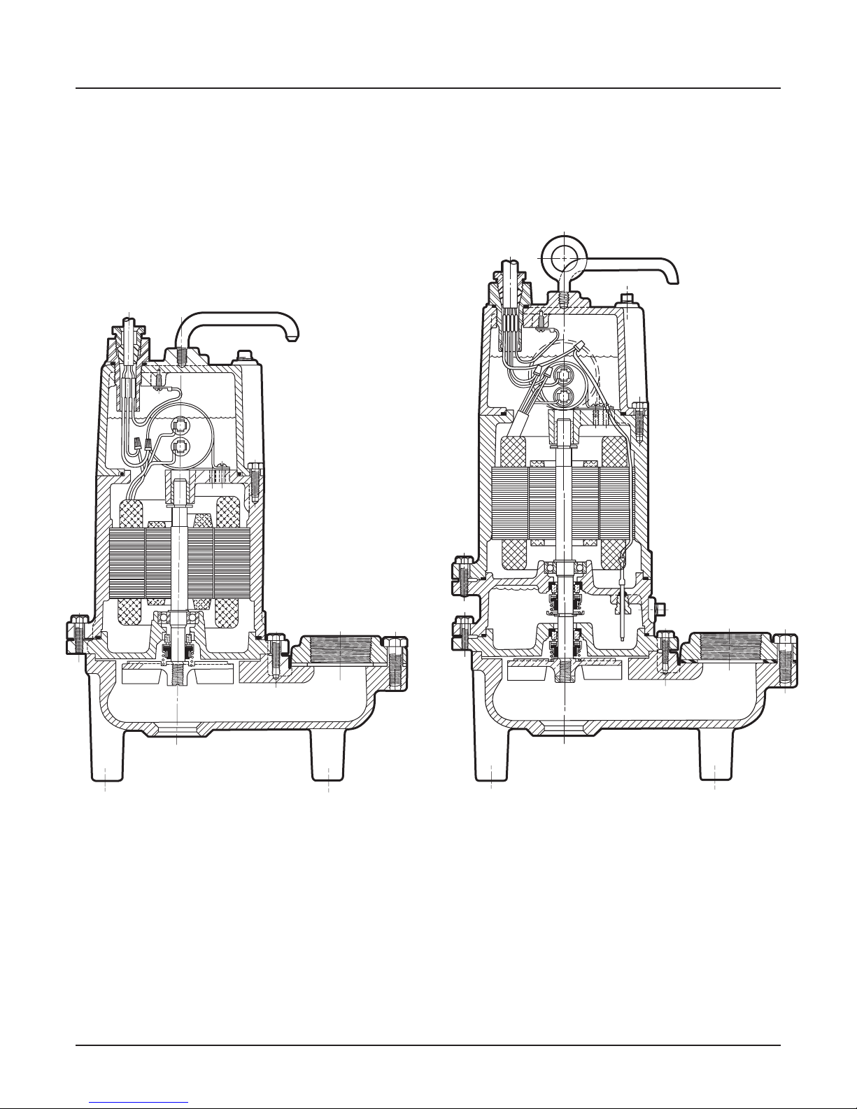
TYPICAL SECTIONAL DRAWINGS
FOR WHR/WHRH AND WHRE
SINGLE AND DOUBLE SEAL WASTE HANDLING PUMPS
SINGLE SEAL
FIG. 1
WHR
WHRH
WHRE
23833A201 2
DOUBLE SEAL
FIG. 2
WHR-DS WHR-SD L/D
WHRH-DS WHRH-DS L/D
WHRE-DS WHRE-DS L/D

GENERAL DESCRIPTION AND USES
The WHR and WHRH Series are solids handling
pumps that can be used to pump RAW SEWAGE
for COMMERCIAL and DOMESTIC use, but are
not intended to handle large rags, mop heads, or
strings. All pumps can be used for normal sump
duty where extra capacity is required.
The WHRE Series is for pumping sump water
and EFFLUENT from septic tanks only. DO NOT
USE FOR RAW SEWAGE.
Plug in cords can be used on all the single phase
pumps without seal leak detector. The cord
has a GROUND pin that plugs into a grounded
receptacle. The grounded receptacle cannot be
used in the wet sump or basin due to DANGER
of current leakage.
Sealed junction boxes must be used in wet sumps
or basins to make connections to motor cord. The
AWS-1 control also acts as a sealed junction box
for connecting power cord to pump cord.
RECESSED IMPELLERS
All of the pumps are of the recessed impeller
type that provides a clear volute passage for
solids as no solids pass through the impeller.
All of the pumps listed can be used to pump
septic tank EFFLUENT or GROUND sewage as
used in some pressure sewer systems.
DOUBLE SEAL PUMPS
All double seal models have two seals with an oil
chamber between the seals so that seal faces of
both lower and upper seals are oil lubricated for
longer life and greater protection against water
leaking into the motor windings. These double
seal units are made with and without a seal leak
probe. The leak probe in the oil seal chamber
detects any water leakage into the chamber and
turns on a red signal light in the control panel.
Pumps should be removed from sump and seals
replaced after seal light shows in the panel.
Control panels must be used for pumps having
the seal leak probe.
Double seal pumps without the seal leak probe,
should be pulled and seal leak checked in 12 to
18 months.
LEVEL CONTROLS
All pumps must use sealed level control switches
for automatic operation. MLC and MFLC controls
have sealed mercury* switches that are 1 H.P.
rated at 230 volts. ALC and AWS-1 controls have
sealed mechanical switches that are rated 2 H.P.
at 230 volts.
Simplex single phase pumps can be made
automatic by attaching MFLC or MLC controls
to pump. These switches have a fixed draw off
level of 8 to 10” and can be used up to 1 H.P. For
higher H.P. ratings two mercury* switch (or SMNO)
controls with a magnetic starter can be used.
The ALC and AWS-1 controls can be used for
simplex single phase pumps with ratings up to 2 H.P.
SAFETY WARNING
All pumps single or three phase must have a
GROUND WIRE that is connected to a screw
in the metal pump housing. This wire goes to
the control box and is connected to a good
outside GROUND such as a metal water pipe or
GROUND STAKE driven at least 6 feet into the
ground.
MOTOR TYPES
All single phase pump motors are of the
permanent split capacitor type that do not
require a start switch or start relay.
Automatic reset overload switches are attached
directly to the motor windings.
Three phase pump motors require a magnetic
starter with 3 leg overload protection.
INSTALLATION
Pumps can be installed inside sealed basin
with proper venting for either simplex or duplex
systems. SIMPLEX or DUPLEX basin systems
are available. See Figs. 3 and 4.
It is not recommended that basins be used for
RAW SEWAGE inside the home, but are for use
in office buildings and small industrial buildings
and factories.
*This product contains mercury and must be disposed of according to local
3 23833A201
and federal codes.
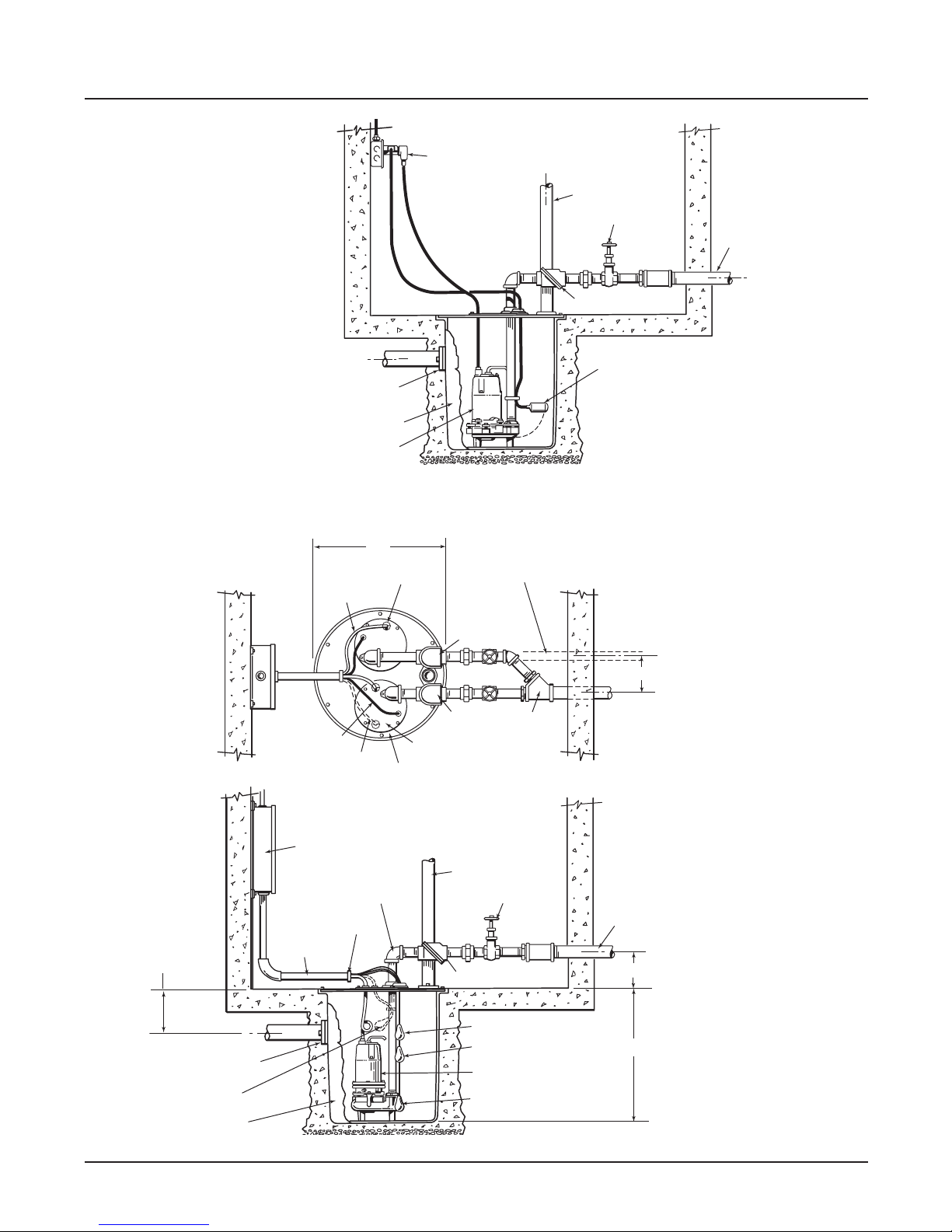
“O” RING SEAL INLET
FLANGE FOR 4
PLASTIC PIPE
FIBERGLASS BASIN
WHR – WHRH – WHRE
SEWAGE PUMP
SINGLE PHASE
1
/2-3/4-1-2 HP
1
/2” O.D.
PUMP CORD PLUGS INTO
SERIES SWITCH CORD FOR
AUTOMATIC OPERATION
3” VENT PIPE
GATE VALVE
MYERS FREE FLOW
CHECK VALVE
MLC or MFLC
LEVEL CONTROL
WITH SERIES PLUG
SIMPLEX SYSTEM WITH
ALC LEVEL CONTROLS.
DISCHARGE PIPE
FIG. 3
NOT MORE THAN 14”
HEIGHT
TO SUIT
“O” RING SEAL INLET
FLANGE FOR 41/2” O.D.
PLASTIC PIPE
OPTIONAL ALARM
CONTROL
30” DIA. x 36” DEEP
FIBERGLASS BASIN
PUMP CORD
LEVEL CONTROL
CORD
OPTIONAL ALARM
CORD
NEMA 1 DUPLEX
CONTROL BOX
2” PUMP PIPING,
CAN BE 3” IF
REQUIRED
1
1
/2” CONDUIT
BUSHING
1
1
/2” CONDUIT
35”
SPLIT RUBBER
SEAL BUSHING
PUMP 1
CAST IRON PUMP COVER
SEALS WITH RUBBER GASKET
STEEL BASIN COVER EPOXY
COATED. SEALED TO BASIN
WITH CAULKING COMPOUND
SEPARATE 2” DISCHARGE
PIPE CAN BE RUN FROM
EACH PUMP IF DESIRED
PUMP 2
3”– 45º TEE
3” VENT PIPE
2” GATE VALVE
CV-200 CHECK VALVE
OVERRIDE CONTROL
START CONTROL
WASTE HANDLING PUMPS
STOP CONTROL
10”
3” DISCHARGE
PIPE
10”
REMOTE CONTROL BOX.
36”
DUPLEX SYSTEM WITH
FLOAT CONTROLS AND
FIG. 4
23833A201 4

Basins can be used inside the home where extra
capacity sump pumps are required for water
softeners and wash water.
If raw sewage must be pumped in the home use
outside basins that connect with pressure sewer
mains or gravity sewers, or run to septic tanks.
If an inside basin is used it is usually installed at
time of pouring the concrete floor.
Pumps can be installed in a compartment of septic
tanks for pumping to pressure sewer mains, gravity
sewers, leach fields, or evaporation mounds. See
Figs. 5, 6 and 7.
PROPER VENTING FOR BASINS
INSTALLED INSIDE
All inside sealed basins must have a 2” or 3” vent
pipe installed in accordance with local codes.
Sumps for handling softener water, wash or
drainage water do not have to be sealed or vented.
Outside basins are usually of fiberglass and from
4 to 8 feet deep and have a sealed cover. Pump
is usually installed with a lift out rail system so
that pump can be removed without disturbing the
discharge piping. The check valve comes out with
pump for servicing. Complete LIFT OUT SYSTEMS
mounted in fiberglass basins are available to meet
customer’s specifications.
WARNING: Sump basin must be vented in accordance with local plumbing codes. These pumps
are not designed for and CANNOT be installed in
locations classified as hazardous in accordance
with the National Electric Code ANSI/NFPA 70.
PIPING
Pumps are fitted with 2” or 3” female threaded
pipe flange. Galvanized or PVC plastic pipe can be
used. Plastic pipe is preferred for raw sewage or
septic tank effluent.
CHECK VALVES AND SHUT-OFF VALVES
All pumps must have check valves and shut-off
valves in the discharge line. Check valves must be
flapper type with outside spring or ball type. Shutoff valves can be ball or gate type. Plastic construction for both check and shut-off valves is preferred.
STARTING SIMPLEX SYSTEMS
1. For single phase pumps with MLC or MFLC
control, plug cords piggy back into receptacle
and run water into sump until pump starts. Allow
pump to make several on/off cycles. Leave
power cord plugged in. If pump runs but does
not pump it may be air locked. Unplug cord and
crack union in the discharge line then restart
pump, this should vent off any trapped air.
Re-tighten union.
AIR LOCKING
A sump pump is said to be air locked if water traps in the pump and
it cannot get out, thus preventing pump from operating.
ALL MYERS SUMP PUMPS HAVE A SMALL AIR VENT HOLE IN
THE IMPELLER CHAMBER TO LET OUT TRAPPED AIR. IF THIS
HOLE BECOMES PLUGGED, PUMP MAY AIR LOCK. THIS
USUALLY HAPPENS ON PUMPS THAT ARE USED MAINLY IN THE
SEASONS. IN SUMMER MONTHS, THE PUMP MAY BE TURNED
OFF AS SUMP WATER DRIED UP. WHEN PUMP IS TURNED ON
AGAIN AND WATER COMES UP IN SUMP, THE AIR WILL TRAP IN
PUMP IF NOT VENTED.
AS A SECONDARY PRECAUTION IN INSTALLATIONS OF THIS
TYPE – 1/8” HOLE SHOULD BE DRILLED IN THE DISCHARGE PIPE
BELOW THE CHECK VALVE. THE CHECK VALVE SHOULD BE 12
TO 18 INCHES ABOVE PUMP DISCHARGE. DO NOT PUT CHECK
VALVE DIRECTLY INTO PUMP DISCHARGE OPENING.
In normal sumps where the pump is operating daily, air locking
rarely occurs.
2. With 2 float controls turn on power at the control
box and run water into sump. When level gets
above top control pump should start and
continue to pump until level drops to lower
control stopping pump. Run pump through
several cycles. If pump runs but does not pump,
check air lock as in 1. Leave power on for
automatic operation.
3. Where ALCL or AWS-1 controls are used plug
in cord or turn on power and run water into
sump, when level is about half way up on upper
weight pump should start and run until level
drops until about half the lower weight is above
water, stopping pump. Check 1, if pump does
not operate properly. For all cases if motor does
not start when water level is up check for proper
plug in or that start switch is on, or if fuse is
blown. ALWAYS HAVE ELECTRICTIAN MAKE
ELECTRICAL CHECKS.
STARTING PUMP “WHE-P” (AUTOMATIC)
USING MECHANICAL SWITCH WITH
SERIES PLUG-SIMPLEX SYSTEM
1. These pumps have a mechanical (mercury-free)
float switch with a 20 ft. cord and 115 volt or 230
volt series piggy-back plug on ½ H.P. with switch
mounted to the pump. On ¾ H.P. and 1 H.P., it
requires 20 ft. cord and 230 volt only.
2. Plug the switch cord plug into a proper voltage
properly grounded outlet.
3. Plug the pump power cord into the back of the
switch cord series plug.
4. Tape the cords to the discharge pipe every 12”.
5. Run water into sump until pump starts. Be sure
discharge line valve is open.
6. Allow pump to operate through several on/off
cycles.
7. If pump does not operate properly, see trouble
shooting service chart for remedy.
5 23833A201

HOW TO SET CONTROLS AND START
DUPLEX SYSTEMS
CONTROL BOX MUST BE USED ON ALL
DUPLEX SYSTEMS
1. 4 float controls are used for duplex systems.
Set turn-on control 6” to 8” above pumps. Set
turn-off control 8” to 10” above bottom of
sump. Set override control 6” to 8” above turn on control. Set high level alarm control about 6”
to 8” above override control. Mark all control
cords so that they can be
connected correctly in
the control box. See Fig. 4.
2. Turn Hand-Off-Auto switches to OFF position
and close circuit breaker.
3. Turn H-O-A switches to the AUTO position and
run water into sump. When level floats up and
activates the turn-on switch one pump should
start and run, pump will continue to run until
lower control is exposed stopping pump.
4. Run water into sump again and when level
floats up turn-on control, opposite pump will
start and run until level drops exposing lower
control, stopping pump.
5. Run this test several times to be sure pumps
are alternating properly.
LEVEL CONTROL SYSTEMS AVAILABLE
1. Simplex single phase packaged automatic
system. This system has the MLC or MFLC
float switch attached directly to the
pump. This system has a fixed pump-off level
of 8” to 10” and is usually used for drainage
water and is good up to and including 1 H.P.
2. Simplex single phase pumps can use the ALC
or AWS-1 controls which are mounted separate
from the pump. These controls can be used up
to 2 H.P. motors. See Fig. 3
3. Simplex pumps can use two float controls
mounted separate from the pump. These
controls must be used with a control box and
magnetic contactor. These controls can be
spaced apart for any draw off level required and
can be used for 2 H.P. or larger motors.
4. Duplex pump systems must use only the
float controls with electrical control box.
These control boxes mounted remote from the
sump tank are generally of plastic construction
for best corrosion resistance. See Fig. 4.
MOTOR OVERLOAD PROTECTION
All single phase motors have built-in automatic
reset overload switches fastened directly to the
motor windings.
All 3 phase motors must be installed with magnetic
starters having 3 leg overload protection.
HOW TO SET CONTROLS AND START
SIMPLEX SYSTEMS
1. Automatic systems – These systems have the
MLC, MFLC, or ALC switches mounted on the
pump, so pump is installed in the sump and
motor cord is plugged into GROUNDED
receptacle. For sealed sump cover, power cord
is brought through a split rubber plug in the
sump cover.
2. Where 2 float controls are used the turn on
control is set 3” to 6” above top of motor,
and the turn-off control is set about 6” to *’
above bottom of sump. If a high level alarm
control is used it is set about 6” above upper
control. If sump depth will not allow these
settings closer spacing can be used.
3. Where ALLC or AWS-1 controls are used the
DISPLACEMENT WEIGHTS are set so that turn on weight is 4” to 6” above top of motor and
lower weight is set about 6” above sump bottom.
4. Repeat this operation with one pump off which
will duplicate a failed pump condition. When
the level reaches the override control the pump
that is turned on should start and run and
pump down sump level.
5. To check high level alarm, again turn both
switches to OFF and fill sump until level is above
the alarm control. Turn switches to Auto position
and ALARM BUZZER should sound and alarm
light should come on. When level drops below
the alarm control buzzer should stop.
6. If pumps operate as described then set both
H-O-A to Auto and pumps are ready to operate
automatically.
7. If pumps do not operate properly then check as
described for simplex systems. See page. 13.
CAUTION – NEVER WORK ON PUMPS OR
CONTROL BOXES UNTIL CIRCUIT BREAKERS
ARE TURNED OFF.
Always have a qualified ELECTRICIAN make
electrical connections and service checks.
23833A201 6
SPECIAL INSTRUCTIONS FOR
THREE PHASE PUMPS
1. WARNING! Only qualified persons shall
conduct services and installations of this
pump. The pump must be wired by a
qualified electrician, using an approved
starter box and switching device.
CAUTION! Risk of electric shock. Do not
connect conduit to pump
2. Three phase pumps are always installed with
control boxes having magnetic starters with
3 leg overload protection. DO NOT
TRY TO RUN THREE PHASE PUMPS
DIRECTLY ACROSS THE LINE.
3. To Connect Pump: Run wire from pump to the
bottom of control box or appropriate junction
box suitable for enclosing splice connections.
A hole must be cut into the control box for the
wires. With power to control box off, connect
green (ground) line to ground lug. Connect
black (power) wires to power lead terminals.
Make sure that all wires are inside control box
and not in a position to be pinched or shorted
when the door is closed. See wiring diagrams,
page 8.
4. All three phase motors can run either direction,
ROTATION can be changed by interchanging
any two line leads at magnetic starter. BE
SURE CIRCUIT BREAKER IS OFF BEFORE
MAKING THIS CHANGE.
To find if rotation is correct operate pumps
and check delivery operation. If flow and head
is low (refer to pump curves shown in this
manual) the rotation is wrong. With duplex
pumps check operation of both pumps.
All pump impellers either single or three phase
must turn counterclockwise when looking
into pump inlet. If uncertain of rotation, TURN
OFF POWER and lift pump from basin with
cord connected and lay pump on side so
impeller can be seen. Turn on power and start
pump using hand position of H-O-A switch.
Turn on and off fast so that coast of impeller
can be seen.
ON THE IMPELLER.
leads at the magnetic starter to change rotation.
NEVER PUT HAND OR FINGERS
Interchange any two line
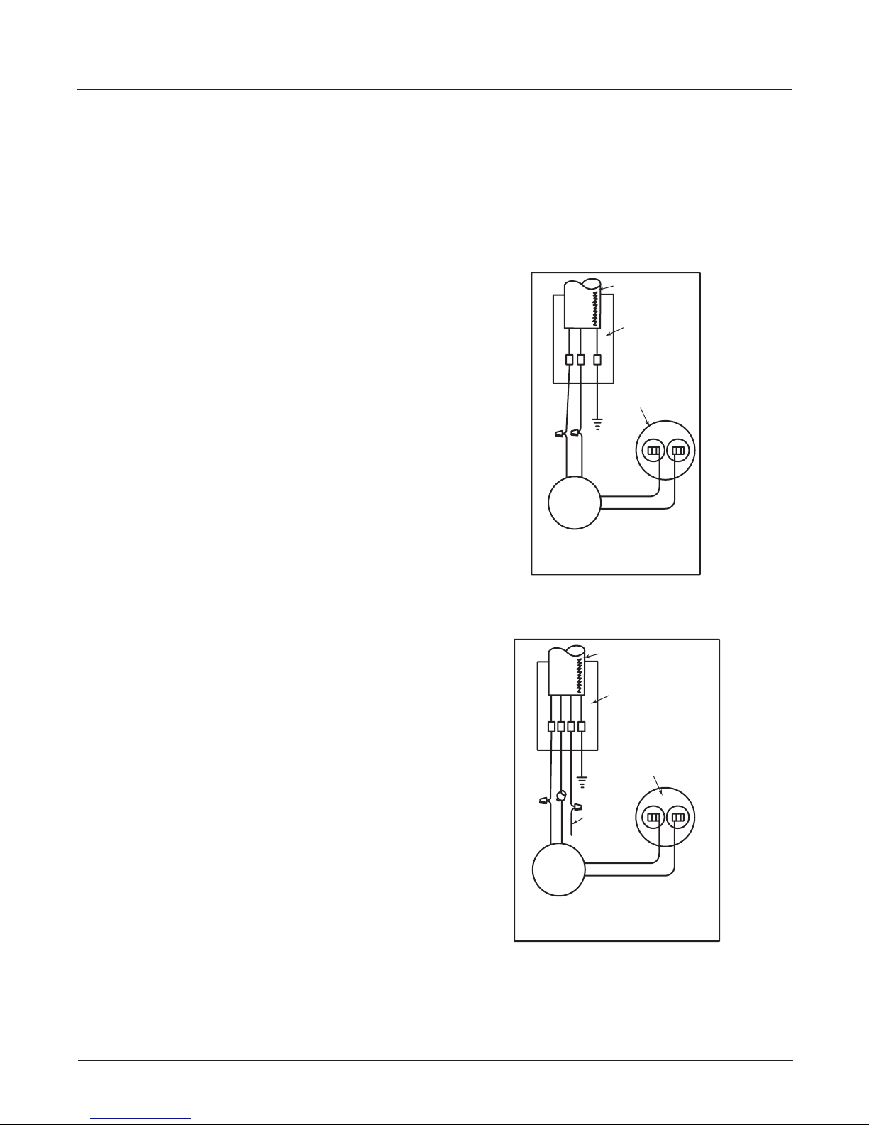
WIRING DIAGRAMS SINGLE PHASE MOTORS
SINGLE PHASE PUMPS
WARNING – Risk of electric shock. This pump
is supplied with a grounding conductor and
grounding-type attachment plug. To reduce
the risk of electric shock, be certain that it
is connected only to a properly grounded,
grounding-type receptacle.
POWER CORD
POTTING
RESIN
CAPACITOR
GRN.
BLACK
WHT. OR YELL
WHITE
BLACK
STATOR
115 VOLT OR
200 or 230 VOLT - 1 PHASE
SINGLE VOLTAGE P.S.C. MOTOR
BROWN
BROWN
SINGLE SEAL PUMPS AND DOUBLE SEAL
PUMPS WITHOUT SEAL LEAK PROBE
POWER CORD
POTTING
RESIN
GRN.
RED
BLACK
WHT. OR YELL
SEAL
LEAK
RED
BLACK
WHITE
ELECTRODE
STATOR
115 VOLT OR
200 or 230 VOLT - 1 PHASE
SINGLE VOLTAGE P.S.C. MOTOR
CAPACITOR
BROWN
BROWN
7 23833A201
DOUBLE SEAL PUMPS WITH
SEAL LEAK PROBE
(RED CONDUCTOR IN POWER CORD
IS FOR SEAL LEAK PROBE)
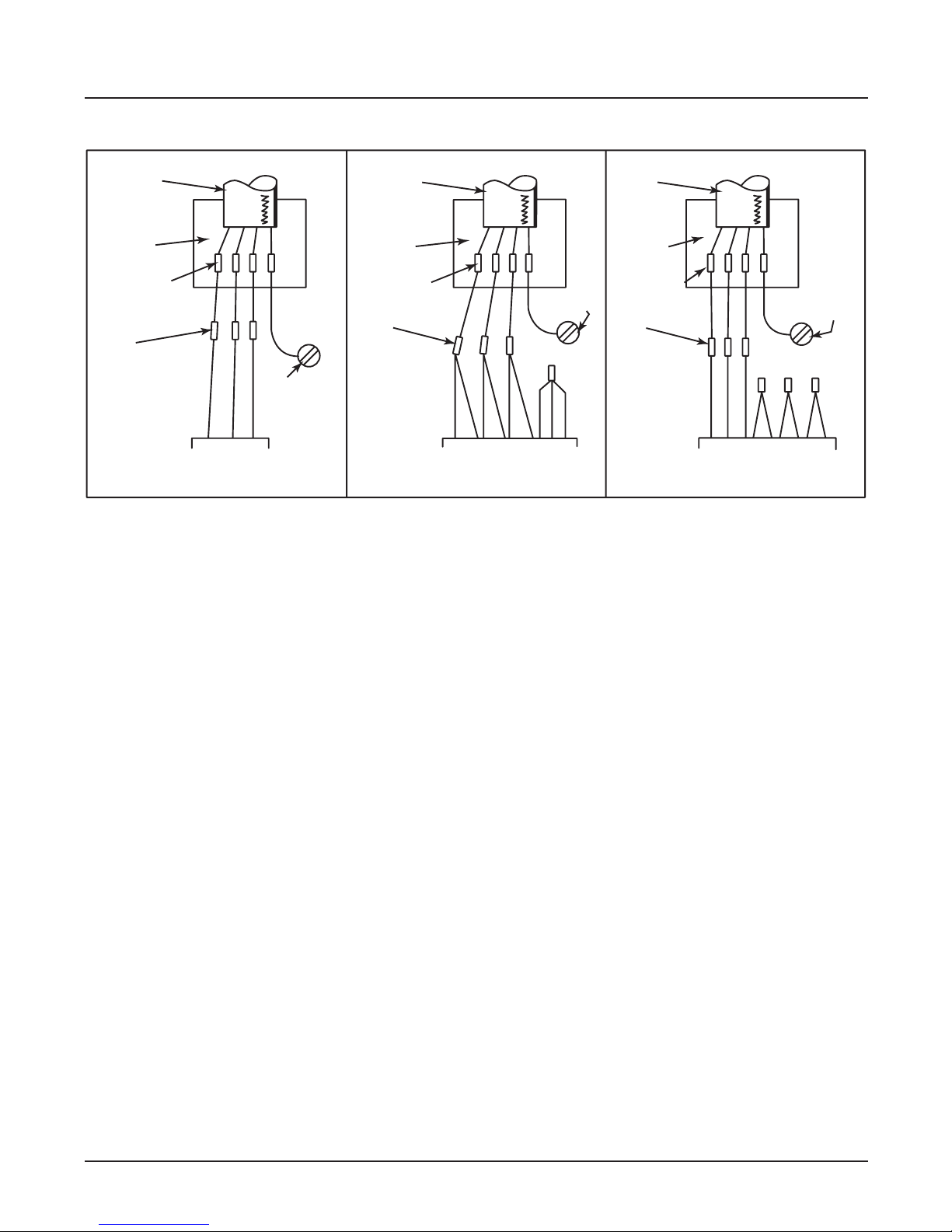
WIRING DIAGRAMS FOR 3 PHASE MOTORS
POWER
CORD
POTTING
RESIN
SPLICES
B
B
B
CONNECTORS
B
B
B
MOTOR STATOR
200 or 575 VOLT - 3 PHASE
FOR SINGLE SEAL PUMPS AND DOUBLE SEAL PUMPS
GREEN
GROUND
SCREW
POWER
CORD
POTTING
RESIN
SPLICES
CONNECTORS
T9
B
B
T8
T3
GROUND
B
SCREW
GREEN
T7
T6
T5
T1
T2
T4
MOTOR STATOR
230 VOLT - 3 PHASE
WITHOUT SEAL LEAK PROBE
POWER
CORD
POTTING
RESIN
SPLICES
CONNECTORS
MOTOR STATOR
460 VOLT - 3 PHASE
B
B
B
T1
T2
T3
T9
GREEN
T6
GROUND
SCREW
T5
T8
T7
T4
23833A201 8
 Loading...