

MYERS SP75, SP75PC1, SP75MC1, SP75P1 Parts Manual

SP75 Series
Submersible Sump Pumps
INSTALLATION, OPERATION, & PARTS MANUAL
SAFETY INFORMATION
Carefully read and follow all safety instructions in this
manual or on pump.
This is the safety alert symbol. When you see this
symbol on your pump or in this manual, look for one of the
following signal words and be alert to the potential for
personal injury!
warns about hazards that will cause serious
personal injury, death or major property damage if ignored.
warns about hazards that can cause serious
personal injury, death or major property damage if ignored.
warns about hazards that will or can cause
minor personal injury or property damage if ignored.
The word NOTICE indicates special instructions which are
important but not related to hazards.
Electrically powered sump pumps normally give many years
of trouble-free service when correctly installed, maintained,
and used. However, unusual circumstances (interruption of
power to the pump, dirt/debris in the sump, flooding that
exceeds the pump’s capacity, electrical or mechanical failure
in the pump, etc.) may prevent your pump from functioning
normally. To prevent possible water damage due to flooding,
consult your dealer about installing a secondary sump
pump, a DC backup sump pump, and/or a high water alarm.
See the “Troubleshooting Chart” in this manual for information about common sump pump problems and remedies.
1. Know the pump application, limitations, and potential
hazards.
2. Disconnect power before servicing.
3. Release all pressure within system before servicing any
component.
4. Drain all water from system before servicing.
5. Secure discharge line before starting pump. An unsecured discharge line will whip, possibly causing personal
injury and/or property damage.
6. Check hoses for weak or worn condition before each
use, making certain that all connections are secure.
7. Periodically inspect sump, pump and system components. Keep free of debris and foreign objects. Perform
routine maintenance as required.
8. Provide means of pressure relief for pumps whose discharge line can be shut-off or obstructed.
9. Personal Safety:
a. Wear safety glasses at all times when working with
pumps.
b. Keep work area clean, uncluttered and properly light-
ed – replace all unused tools and equipment.
c. Keep visitors at a safe distance from work area.
d. Make workshop child-proof – with padlocks, master
switches, and by removing starter keys.
10. When wiring an electrically driven pump, follow all electrical and safety codes that apply.
11. This equipment is only for use on 115 volt and is
equipped with an approved 3-conductor cord and
3-prong, grounding-type plug.
© 2008 MY502 (Rev. 2/20/08)
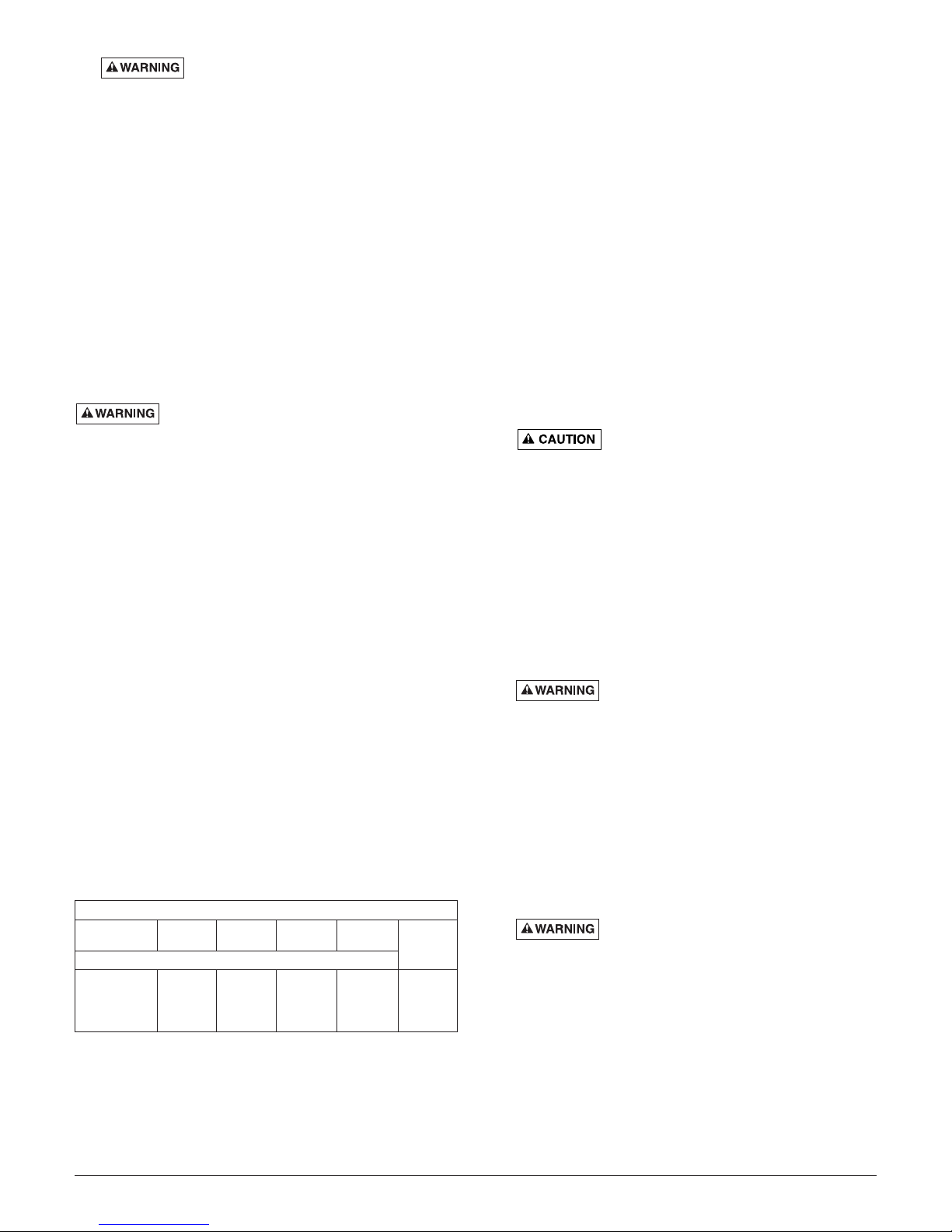
Individual Switch Setting
Model Motor Max. Branch Circuit Cord in inches (mm)
Number HP Load Amps Required (Amps) Length
On Off
SP75P1 3/4 7.5 15 10’ 11" (279) 3-1/2" (89)
SP75PC1 3/4 7.5 15 20’ 11" (279) 3-1/2" (89)
SP75MC1 3/4 7.5 15 20’ – –
MOTOR, SWITCH, & CORD SPECIFICATIONS
1101 Myers Parkway
Ashland, OH 44805
Phone:
1-419-289-6898
Fax:
1-419-289-6658
Web Site:
http://www.myerspump.com
To reduce risk of electric shock, pull
plug before servicing. This pump has not been investigated for use in swimming pool areas. Pump is supplied with a grounding conductor and grounding-type
attachment plug. Be sure it is connected only to a
properly grounded grounding-type receptacle.
Where a 2-prong wall receptacle is encountered, it
must be replaced with a properly grounded 3-prong
receptacle installed in accordance with codes and
ordinances that apply.
12. A ground fault circuit is recommended for use with any
electrical appliance submerged in water. Installation and
all wiring should be performed by a qualified electrician.
13. Make certain power source conforms to requirements of
your equipment.
14. Protect electrical cord from sharp objects, hot surfaces,
oil, and chemicals. Avoid kinking cord. Replace or repair
damaged or worn cords immediately.
15. Do not touch an operating motor. Motors can operate at
high temperatures.
16. Do not handle pump or pump motor with wet hands or
when standing on wet or damp surface, or in water.
Risk of electric shock. If your basement has
water or moisture on floor, do not walk on wet area until all
power has been turned off. If shut-off box is in basement,
call electric company or hydro authority to shut-off service
to house, or call your local fire department for instructions.
Failure to follow this warning can result in fatal electrical
shock. Remove pump and repair or replace.
DESCRIPTION
This Submersible Sump Pump is designed for home sumps.
Unit is equipped with a 3-prong grounding-type power cord. The
permanent split capacaitor motor is oil filled and sealed for
cooler running. The sleeve bearings on the motor shaft never
need lubrication. The pump includes automatic reset thermal
protection.
Pump water only with this pump. Not designed for use as a
swimming pool drainer.
SPECIFICATIONS
Power supply required . . . . . . . . . . . . . . . . . . . .115V, 60 HZ
Liquid Temp. Range . . . . . . . . . . . . . .32° F-77° F (0°-25° C)
Individual Branch Circuit Required . . . . . . . . . . . . .15 Amps
Discharge* . . . . . . . . . . . . . . . . . . . . . . . . . . . . . .1-1/2" Slip
* Use 1-1/4" or 1-1/2" rubber coupling and clamps included
with pump.
NOTE: Do not use where fish are present. Any leakage of oil
from the motor into the water can kill fish. Not for use where
water recirculates.
PERFORMANCE
INSTALLATION
1. Install pump in sump pit with minimum diameter of 14"
(356mm). Sump depth should be 14" (356mm). Construct
sump pit of tile, concrete, steel or plastic. Check local codes
for approved materials.
2. Install pump in pit so that switch operating mechanism
has maximum possible clearance.
3. Pump should not be installed on clay, earth or sand surfaces. Clean sump pit of small stones and gravel which
could clog pump. Keep pump inlet screen clear.
NOTICE: Do not use ordinary pipe joint compound on
plastic pipe. Pipe joint compound can attack plastics.
4. Install discharge plumbing. When using rigid pipe, use
plastic pipe.
Slip rubber coupling over pump discharge. Install and
tighten first clamp. Place second clamp loosely over coupling. Slip coupling over discharge pipe. Clamp hose
tightly with second clamp.
NOTICE: Discharge piping should be as short as possible
to reduce pipe friction losses. Discharge
pipe diameter should be equal to or larger than discharge
size of pump. Smaller pipe diameters will restrict capacity of
pump and reduce performance. Do no use flexible discharge pipe in any permanent installation.
Risk of flooding. Failure to secure
pump may allow pump movement, switch interference and prevent pump from starting or stopping.
If a flexible discharge hose is used, make sure pump is
secured in sump to prevent movement.
5. To reduce motor noise and vibrations, a short length of
rubber hose (e.g. radiator hose) can be connected into
discharge line near pump using suitable clamps.
6. Pumps have an internal check valve to prevent flow backwards through pump when it is shut off.
7. Power Supply: Pump is designed for 115 V., 60 Hz., operation and requires a minimum 15 amp individual branch circuit. Both pump and switch are supplied with 3-wire cord
sets with grounding-type plugs. Switch plug is inserted
directly into outlet and pump plug inserts into opposite end
of switch plug.
Hazardous voltage. Pump should always
be electrically grounded to a suitable electrical ground
such as a grounded water pipe or a properly grounded
metallic raceway or ground wire system. Do not modify cord or plug or cut off round ground pin.
8. Secure discharge line before starting pump.
9. If pump discharge line is exposed to outside sub-freezing
atmosphere, portion of line exposed must be installed so
any water remaining in pipe will drain to the outfall by
gravity. Failure to do this can cause water trapped in discharge to freeze which could result in damage to pump.
10. After piping and check valve (if needed) have been
installed, unit is ready for operation.
11. Check operation by filling sump with water and observing
pump operation through one complete cycle.
Failure to make this operational check
may lead to flooding and premature failure.
NOTICE: This unit is not designed for applications involving salt
water or brine! Use with salt water or brine will void warranty.
TM
E.I. DuPont De Nemours and Company Corporation, Delaware.
2
GPM (LPM) AT TOTAL FEET (m)
5101520
Model (1.5m) (3m) (4.6m) (6.1m)
CAPACITY GALLONS(L)/MINUTE
SP75P1
100 84 64 39 25 Ft.
SP75PC1
SP75M1
(378) (318) (242) (147) (7.6m)
No flow
at height
shown
below
ELECTRICAL
Hazardous Voltage. Can cause severe or
fatal electric shock. Pump is supplied with a grounding con-
ductor and ground ding-type attachment plug. To reduce risk
of electric shock, be certain that it is connected only to a
properly grounded, grounding type receptacle. Ground terminal on pump cord plug is provided for your protection. DO
NOT REMOVE!
A ground fault circuit interrupter is recommended for use with
any electrical appliance submerged in water. For installation
of such a circuit, consult a licensed electrician.
OPERATION / MAINTENANCE
Risk of electric shock. Before attempting to
check why unit has stopped operating, disconnect power
from unit. Do not handle pump with wet hands or when
standing on wet or damp surfaces, or in water.
Risk of flooding. If a flexible discharge hose
is used, pump may move when motor starts. If the switch hits
the side of the sump, the switch may stick and prevent the
pump from starting. Make sure the pump is secured so it
cannot move around in sump.
Risk of sudden starts. The pump motor is
equipped with automatic resetting thermal protector and
may restart unexpectedly.
1. If protector trips, motor may be overloading. Check for
the following problems:
A. Not enough back pressure in discharge pipe.
B. Voltage too high or too low.
C. Wires to motor too small.
D. Motor incorrectly connected to power supply wires.
E. Defective motor.
2. Shaft seal depends on water for lubrication and cooling.
Do not operate pump unless it is submerged in water as
seal may be damaged if allowed to run dry.
3. Motor is equipped with automatic reset thermal protector.
If temperature in motor should rise unduly, switch will cut
off all power before damage can be done to motor. When
motor has cooled sufficiently, switch will reset automatically and restart motor. If protector trips repeatedly,
unplug the pump and remove it; check for cause of difficulty. Low voltage, long extension cords, clogged
impeller, very low head or lift, etc., could cause cycling.
4. Pump will not remove all water. If manually operated
pump is operating and suddenly no water comes out discharge hose, shut off unit immediately. Water level is
probably very low and unit has broken prime.
CLEANING AND REPLACING
IMPELLER
1. Unplug the pump.
2. Loosen the clamps on the hose and clamp assembly.
3. Slide the hose and clamp assembly up on the discharge
pipe and remove the pump from the sump.
4. Turn the pump upside down and remove the screw securing
the pump screen.
5. Loosen and remove the clamp that holds the lower and
upper pump housings together. Remove the lower pump
housing.
6. Hold the motor shaft with a screwdriver in the slot on the
bottom end of the shaft, and unscrew the impeller off of the
shaft.
7. Clean and replace the impeller as necessary.
8. Reverse Steps 1 through 6 above to replace the impeller
and reinstall the pump.
9. Fill the sump with water and run the pump through one
complete cycle to make sure that it is correctly reassembled
and operating as it should.
AUTOMATIC FLOAT SWITCH INSTALLATION
1. Install pump following installation and operating instructions.
2. Automatic float switch is sealed and factory adjusted for
most home sumps. See Page 1 for switch settings.
3. Be sure that horizontal float switch clearance is 8". For
best performance of pumps with tethered switches, sump
diameter and sump depth should be at least 14".
4. Plug piggyback switch cord into 115V AC outlet. Then,
plug pump into piggyback switch cord. Do not allow cord
to interfere with float control motion or to drape over pump
motor. With electrician's tape or cable ties secure cord to
discharge pipe for cord protection.
FLOAT SWITCH OPERATIONAL CHECK
1. Fill the sump with correct amount of water to check operation and tightness of connections. During the first automatic cycle, it may take 30 seconds or more before pump
is primed and pumping. Pump will start as indicated in
the “Motor, Switch and Cord” Specifications Table, Page
1.
2. Check turn-off position. Pump will stop approximately as
indicated in the “Motor, Switch and Cord” Specifications
Table, Page 1.
3. If pump does not operate check electrical service.
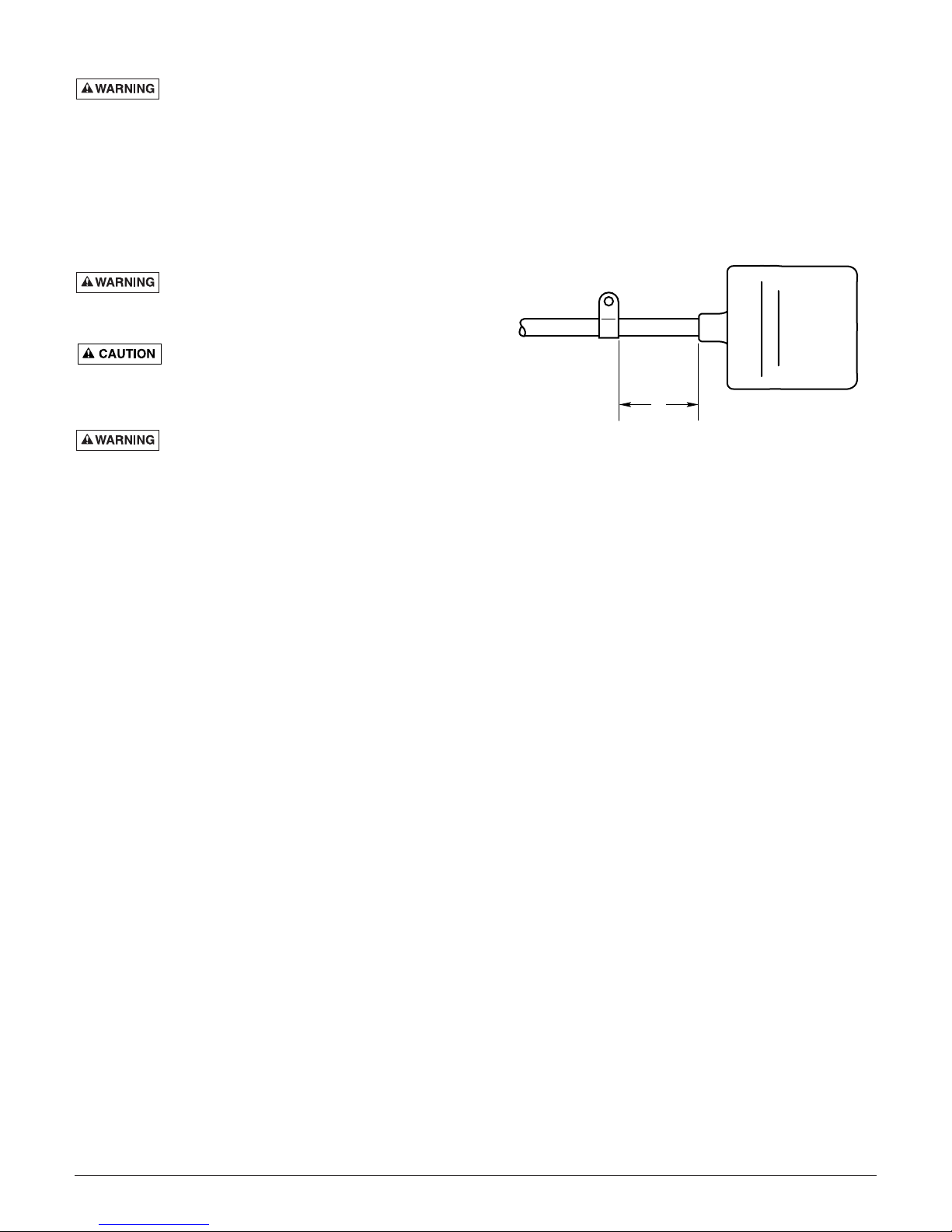
NOTICE: Float switch tether length is set at factory. It is
3" (76mm) for SP75 Series pumps. Do not change tether
length of float switch. Float must swing through its complete arc without interference.
3
Float Switch Tether Length
3"
(76 mm)
4
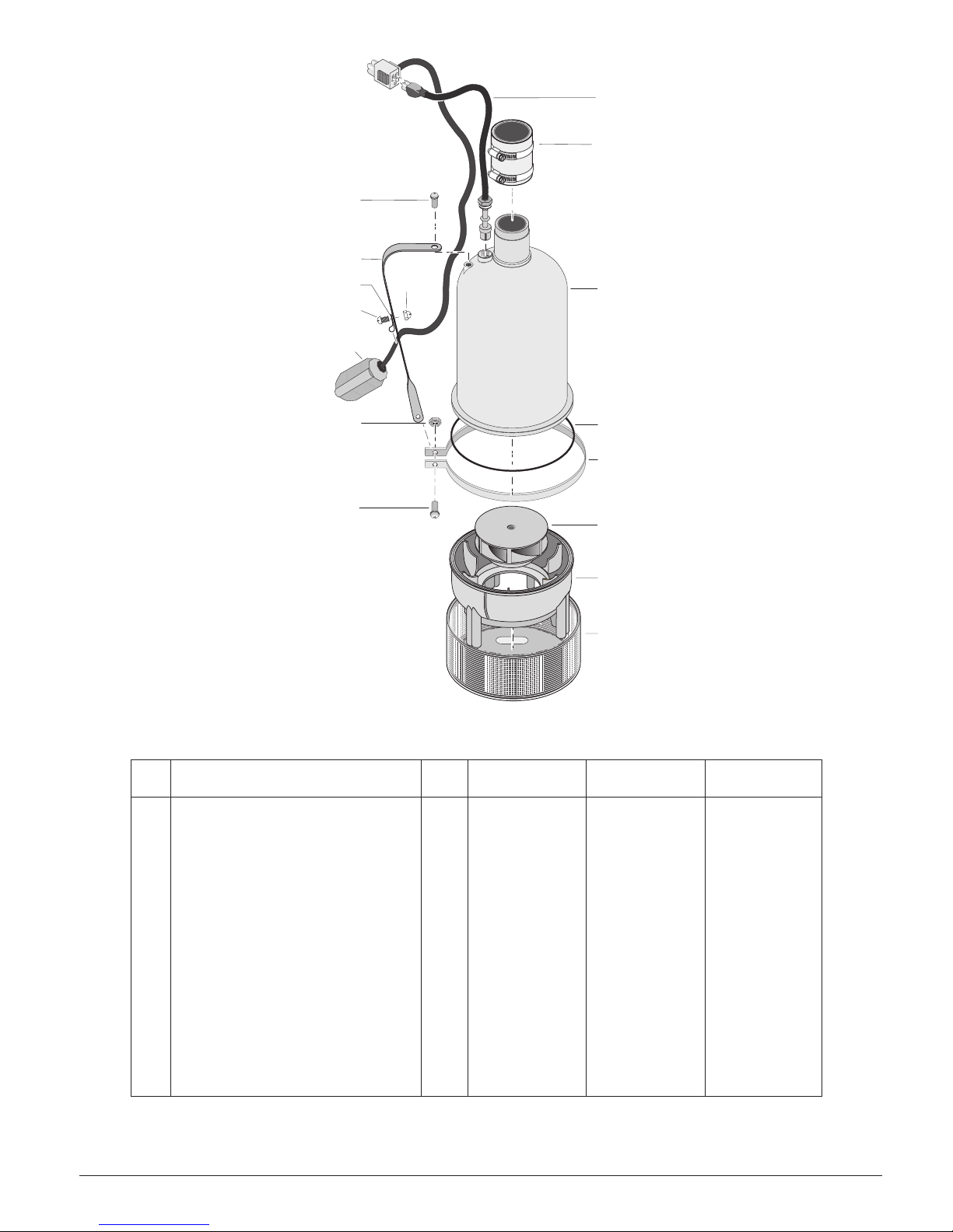
REPLACEMENT PARTS LIST
16
• Not illustrated.
**If motor fails, replace entire pump.
***Not available as a replacement part.
Key
No. Description Qty. SP75P1 SP75PC1 SP75MC1
1 Power Cord Assembly 1 1513001-TSU 1513002-TSU 1513002-TSU
2 Hose and Clamp Assembly 1 U74-68 U74-68 U74-68
3 Upper Pump Housing*** 1 12920 12920 12920
4 O-Ring 1 10801 10801 10801
5 Housing Clamp 1 15146 15146 15146
6 Impeller 1 PS105-1P PS105-1P PS105-1P
7 Lower Pump Housing*** 1 12084 12084 12084
8 Pump Screen 1 12924 12924 12924
9 Screw, Panhead 4327 4327 4327
10 Hex Nut 1 U36-105SS U36-105SS U36-105SS
11 Automatic Float Switch Assembly 1 PS17-109 PS17-111 –
12 Screw, Panhead 1 U30-971SS U30-971SS –
13 Switch Cord Clamp 1 CC0030-13 CC0030-13 –
14 Nut, Acorn, SS 1 U36-203SS U36-203SS –
15 Float Bracket/Handle 1 PS54-14SS PS54-14SS –
16 Screw, Handle 1 14000 14000 14000
• Screw, Screen 1 U30-955PS U30-955PS U30-955PS
• Motor 1 ** ** **
MODELS
SP75P1
SP75PC1
SP75MC1
15
13
12
11
14
1
2
3
10
9
4
5
6
7
8
5446 0706

5
SYMPTOM PROBABLE CAUSE(S) CORRECTIVE ACTION
Pump won’t start or run. Blown fuse. If blown, replace with fuse of proper size.
Low line voltage. If voltage under recommended minimum, check size of wiring from
main switch on property. If OK, contact power company or hydro authority.
Defective motor. Replace pump.
Defective float switch. Replace float switch.
Impeller. If impeller won’t turn, remove lower pump body and locate source of binding.
Float obstructed. Remove obstruction.
Pump starts and stops Backflow of water from piping. Install or replace check-valve.
too often.
Faulty float switch. Replace float switch.
Pump won’t shut off. Defective float switch. Replace float switch.
Restricted discharge Remove pump and clean pump and piping.
(obstacle in piping).
Float obstructed. Remove obstruction.
Pump operates but Low line voltage. If voltage under recommended minimum, check size of wiring from main
delivers little or no water. switch on property. If OK, contact power company or hydro authority.
Something caught in impeller. Clean out impeller.
Worn or defective parts or Clean impeller if plugged; otherwise replace pump.
plugged impeller.
TROUBLESHOOTING CHART
NOTICE: A plugged screen can be mistaken for a faulty switch. Unlike other pumps, screen and impeller design of pump can
provide significant flow, even when screen is nearly plugged. If pump runs continuously or for extended periods, FIRST check
for a DIRTY SCREEN.

6
LIMITED WARRANTY
F.E. MYERS warrants to the original consumer purchaser (“Purchaser” or “You”) of the products listed below,
that they will be free from defects in material and workmanship for the Warranty Period shown below.
Product Warranty Period
Jet pumps, small centrifugal pumps,
whichever occurs first:
submersible pumps and related accessories 12 months from date of original installation, or
18 months from date of manufacture
Fibrewound Tanks 5 years from date of original installation
Steel Pressure Tanks 5 years from date of original installation
Sump/Sewage/Effluent Products 12 months from date of original installation, or
18 months from date of manufacture
Our warranty will not apply to any product that, in our sole judgement, has been subject to negligence,
misapplication, improper installation, or improper maintenance. Without limiting the foregoing, operating a
three phase motor with single phase power through a phase converter will void the warranty. Note also that
three phase motors must be protected by three-leg, ambient compensated, extra-quick trip overload relays of
the recommended size or the warranty is void.
Your only remedy, and F.E. MYERS’s only duty, is that F.E. MYERS repair or replace defective products (at
F.E. MYERS’s choice). You must pay all labor and shipping charges associated with this warranty and must
request warranty service through the installing dealer as soon as a problem is discovered. No request for
service will be accepted if received after the Warranty Period has expired.This warranty is not transferable.
F.E. MYERS SHALL NOT BE LIABLE FOR ANY CONSEQUENTIAL, INCIDENTAL, OR CONTINGENT
DAMAGES WHATSOEVER.
THE FOREGOING WARRANTIES ARE EXCLUSIVE AND IN LIEU OF ALL OTHER EXPRESS AND
IMPLIED WARRANTIES, INCLUDING BUT NOT LIMITED TO THE IMPLIED WARRANTIES OF
MERCHANTABILITY AND FITNESS FOR A PARTICULAR PURPOSE. THE FOREGOING WARRANTIES
SHALL NOT EXTEND BEYOND THE DURATION EXPRESSLY PROVIDED HEREIN.
Some states do not allow the exclusion or limitation of incidental or consequential damages or limitations on
the duration of an implied warranty, so the above limitations or exclusions may not apply to You. This warranty
gives You specific legal rights and You may also have other rights which vary from state to state.
This warranty supersedes and replaces all previous warranty publications.
F.E. MYERS
1101 Myers Parkway, Ashland, OH 44805-1989
Phone: 419-289-6898 • Fax: 419-289-6658 • www.femyers.com
 Loading...