

Myers ME40 Installation Manual
ME40/ME40AG SERIES
Submersible Sump,
Effluent & Sewage Pumps
Installation and Service Manual
Automatic and manual models. Single phase power only — 115 or 230 volt.
23833A245 (Rev. 7/30/10)
DESCRIPTION AND APPLICATION
ME40
Myers ME40 Series Pumps are single seal units,
automatic or manual, designed for use in effluent
dosing. Septic Tank Effluent Pumping (S.T.E.P.) or
normal sump and general dewatering applications
where higher pressure is required. DO NOT USE FOR
RAW SEWAGE.
When used in effluent dosing or S.T.E.P. applications,
the pump must be installed in a separate tank or
compartment at the discharge side of the septic tank.
NEVER INSTALL PUMP IN MAIN TANK WHERE
SLUDGE COLLECTS.
Impellers are enclosed two-vane type to handle
3/4” spherical solids and are made of engineered
thermoplastic. All pumps have a 1-1/2” NPT
discharge tapping. NOTE: DO NOT OVERTIGHTEN
DISCHARGE PIPE INTO PUMP PLASTIC
DISCHARGE FITTING.
General
These pumps are available in 115 volt or 230 volt,
single phase, 4/10 HP motors. All units are single seal
only, available in automatic or manual with either 10’ or
20’ power cords. All power cords have either 115 volt
or 230 volt grounded plugs.
These pumps are NOT for use in swimming pools or
fountains.
ME40AG
The ME40AG Series Pumps are single seal units
designed for use in continuous run agricultural
evaporative cooling applications. They will run
continuously in elevated temperatures with clean
sump water.
The wetted pump components are the same as
already described for the ME40 series.
AIR LOCKING
A sump pump is said to be air locked if water traps air
in the pump and it cannot get out, thus preventing the
pump from operating.
PACKAGING
Each pump is packaged separately in a carton marked
with a catalog number and Myers engineering number.
Catalog Engineering Cord
No. No. HP V Ph Lgth. Type
ME40A-11 25300D000 4/10 115 1 10’ Auto
ME40M-11 25300D001 4/10 115 1 10’ Manual
ME40AC-11 25300D010 4/10 115 1 20’ Auto
ME40MC-11 25300D011 4/10 115 1 20’ Manual
ME40AC-21 25300D012 4/10 230 1 20’ Auto
ME40MC-21 25300D013 4/10 230 1 20’ Manual
ME40P-1 25300D900 4/10 115 1 10’ Auto
ME40PC-1 25300D901 4/10 115 1 20’ Auto
ME40P-2 25300D902 4/10 230 1 10’ Auto
ME40PC-2 25300D903 4/10 230 1 20’ Auto
ME40AG-11 27234D001 4/10 115 1 20’ Manual
ME40AG-21 27234D002 4/10 230 1 20’ Manual
LEVEL CONTROLS
All pumps must use sealed level control switches for
automatic operation. All automatic pumps have builtin level control float switches. The power cord has a
GROUND PIN that plugs into a grounded receptacle.
The grounded receptacle cannot be used in the wet
sump or basin due to DANGER of current leakage.
Manual pumps can be made automatic with MLC or
MFLC controls with a series plug. Plug the MLC or
MFLC witch cord series plug into a proper voltage
GROUNDED RECEPTACLE. Then plug the pump
cord plug into the back of the switch cord series plug.
NOTE: The float control must be tethered a minimum
4” to pump or discharge pipe. Control must float free
from pump and basin wall.
On all duplex units or simplex installations with
additional options like high water alarm, the power
cord plug must be cut off and wired into a control
panel or into a sealed junction box if used in wet sump
or basin. The AWS-1 control also acts as a sealed
junction box for connecting power cord to pump cord.
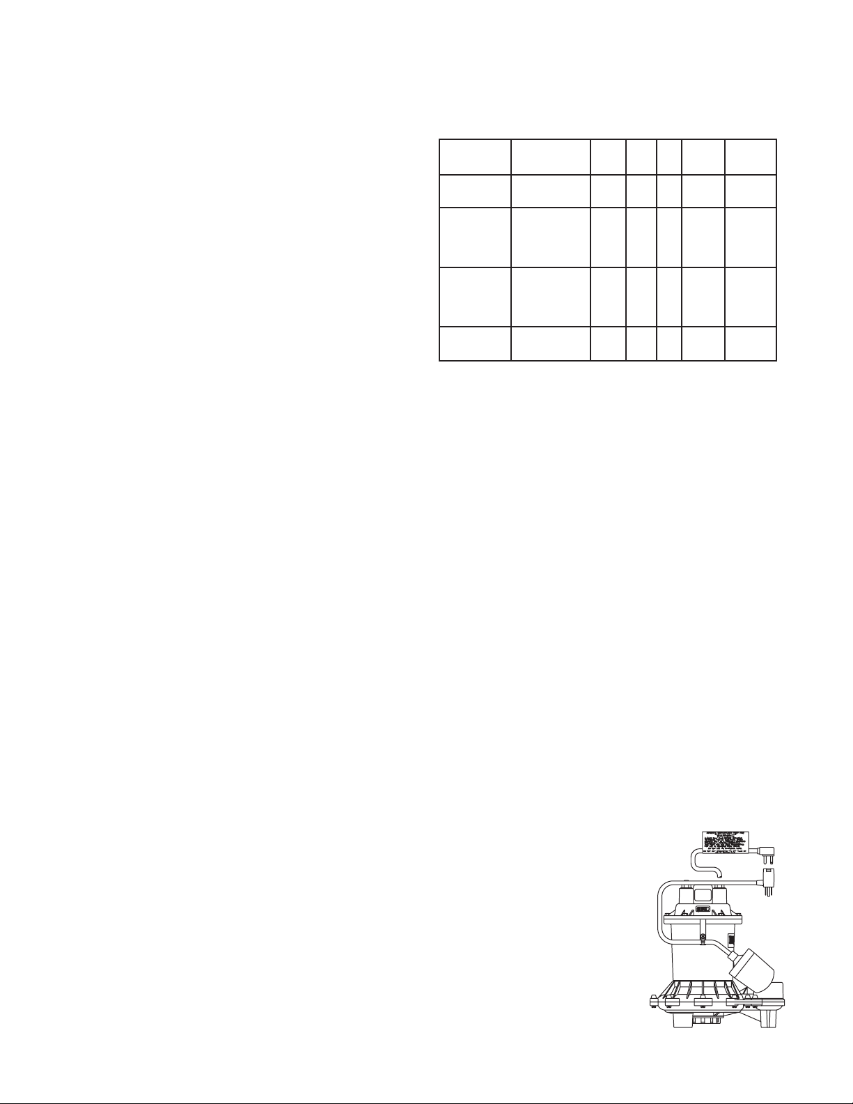
NOTE: The ME40 sump/effluent pump can be easily
changed from one style, automatic or manual, to the
other by only interchanging the plug ends of the float
control with the manual plug. The ball float must be
tethered with a cable clamp, as
shown. DO NOT REMOVE THE
MOTOR CAP.
The ME40/ME40AG pumps have a 1/16” air vent hole
in the impeller chamber to let out trapped air. If this
hole becomes plugged, the pump may air lock. As
a secondary precaution a 1/8” hole should be drilled
in the discharge pipe below the check valve. The
check valve should be 12 to 18 inches above pump
discharge. Do not put check valve directly into pump
discharge opening.
23833A245 2
The ME40P pumps have a
mechanical (mercury free) float
switch with a 10’ or 20’ cord with a
115 volt or 230 volt piggyback
plug with the switch mounted to
the pump. Plug the switch cord
plug into a proper voltage, properly
grounded outlet and plug the
power cord into the back of the
switch cord and tape the cords to
the discharge pipe every 12”.

DESIGN OF PRESSURE SEWER SYSTEMS
Myers has available complete computer software for
designing PRESSURE SEWER SYSTEMS. This
gives pipe sizes to use and gives exact flow from
any pump or group of pumps in the system when
operating simultaneously. This design DISK for IBM®
or COMPATIBLE computers is available to engineers
on request.
MOTOR TYPE
The motors used in the ME40/ME40AG pumps are
pressed into the cast iron housing and surrounded by
dielectric oil for the greatest heat dissipation. The
ME40 uses a shaded pole, 4/10 HP, 1550 RPM motor.
The ME40AG uses a permanent split capacitor, 4/10
HP, 1625 RPM motor. Both units have Class A motor
insulation, are available in single phase 115 or 230 volt
with overload protection, and use a lower ball bearing -
upper sleeve bearing. These pumps have no starting
switches and do not require a control panel for simplex
installation.
SAFETY WARNINGS
WARNING: Risk of electric shock. Pumps are
supplied with a grounding conductor and groundingtype attachment plug on the power cord. To reduce
the risk of electric shock, be certain that it is
connected only to a properly grounded, groundingtype receptacle. DO NOT cut off ground pin or use an
adapter fitting. DO NOT use an extension cord with
this pump. Entire plug may be cut off it a control panel
is used.
When wiring this pump, follow all local electrical and
safety codes and ordinances as well as the most
recent National Electric Code (NEC-ANSI/NFPA 70).
All pumps have a GROUND WIRE that is connected to
the motor. This wire goes to the receptacle or control
panel which must be connected to a good outside
GROUND such as a metal water pipe or GROUND
STAKE DRIVEN AT LEAST 8 feet into the ground.
CAUTION: Never enter pump chamber after
sewage or effluent has been in basin. Sewage
water can give off methane, hydrogen sulfide, and
other gasses which are highly poisonous. For this
reason, Myers recommends installing effluent pumps
with a quick removal system. The quick removal
system may be a union or Cam-lok® coupling if
the pipe or discharge hose is within reach from the
surface, or a rail system type quick disconnect on
deeper installations. See installation drawings for
suggested installation.
The dosing tank or pumping chamber must be
constructed of corrosion resistant materials and must
be capable of withstanding all anticipated internal and
external loads. It also must not allow infiltration or
exfiltration. The tank must have provisions for antibuoyancy. Access holes or covers must be adequate
size and be accessible from the surface to allow for
installation and maintenance of the system. Access
covers must be lockable or heavy enough to prevent
easy access by unauthorized personnel. The pumping
chamber holding capacity should be selected to allow
for emergency conditions.
The discharge pipe must be the same size as the pump
discharge, 1-1/2” or larger. In order to insure sufficient
fluid velocity to prevent any residual solids from
collecting in the discharge pipe, it is recommended that
a minimum flow of 2’ per second be maintained. (12
GPM through 1-1/2” pipe, 21 GPM through 2” pipe and
46 GPM through 3” pipe). It is recommended that PVC
or equal pipe is used for corrosion resistance. A full flow
(ball or gate) shut-off valve must be installed to prevent
back flow of effluent if the pump must be removed for
service. A check valve must be installed on pressure
sewer systems and on other systems where conditions
allow to prevent back flow and to reduce wear on the
pump system.
A high water alarm must be installed on a separate
circuit from the pump circuit. The alarm should have
the ability to be tested for proper operation.
UL AND CSA APPROVAL
All pumps have UL and CSA approval. Myers is a
SSPMA certified pump member.
INSTALLATION
WARNING: Basin or tank must be vented in
accordance with local plumbing codes. These pumps
are not designed for and CANNOT be installed in
locations classified as hazardous in accordance with
the National Electric Code ANSI/NFPA 70.
SCREEN
ME40AG pumps have a suction screen included in
the packaging. To secure the screen in place use two
screws (provided). Screen installation, maintenance,
and cleaning is the responsibility of the pump owner.
BEFORE DISMANTLING PUMP FOR
REPLACEMENT OF PARTS
Clean pump thoroughly. Knock off all scale and
deposits. Submerge complete unit in Clorox solution
for one hour before taking apart.
3
23833A245
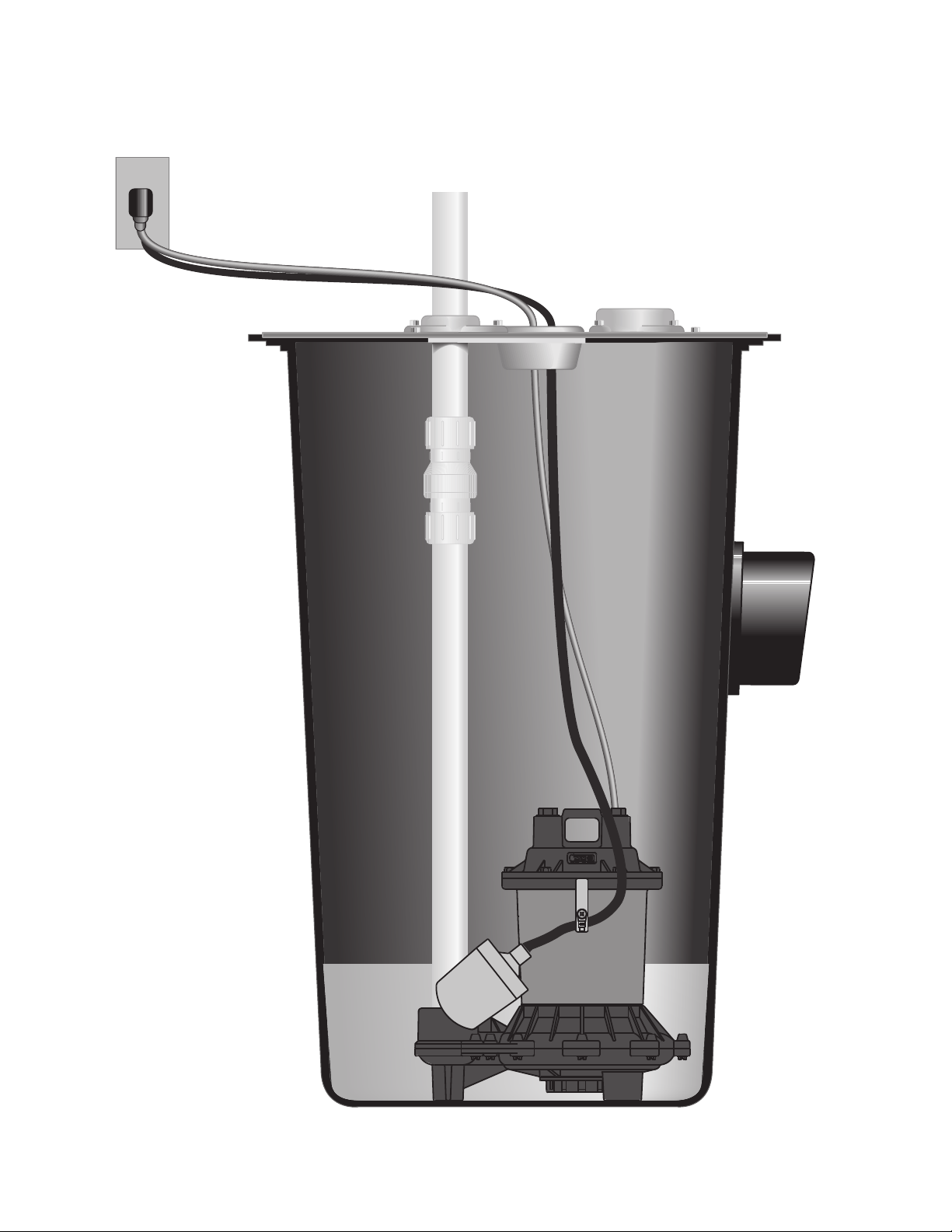
ME40 TYPICAL INSTALLATION
23833A245 4
 Loading...