

Myers ME3 Installation Manual
OWNER’S MANUAL
Submersible Sump / Effluent Pump
ME3F, ME3H Series
293 WRIGHT STREET, DELAVAN, WI 53115 WWW.FEMYERS.COM
PH:
1-888-987-8677
© 2018 Pentair Ltd. All Rights Reserved. 23833A305 (02/27/18)
Important Safety Instructions
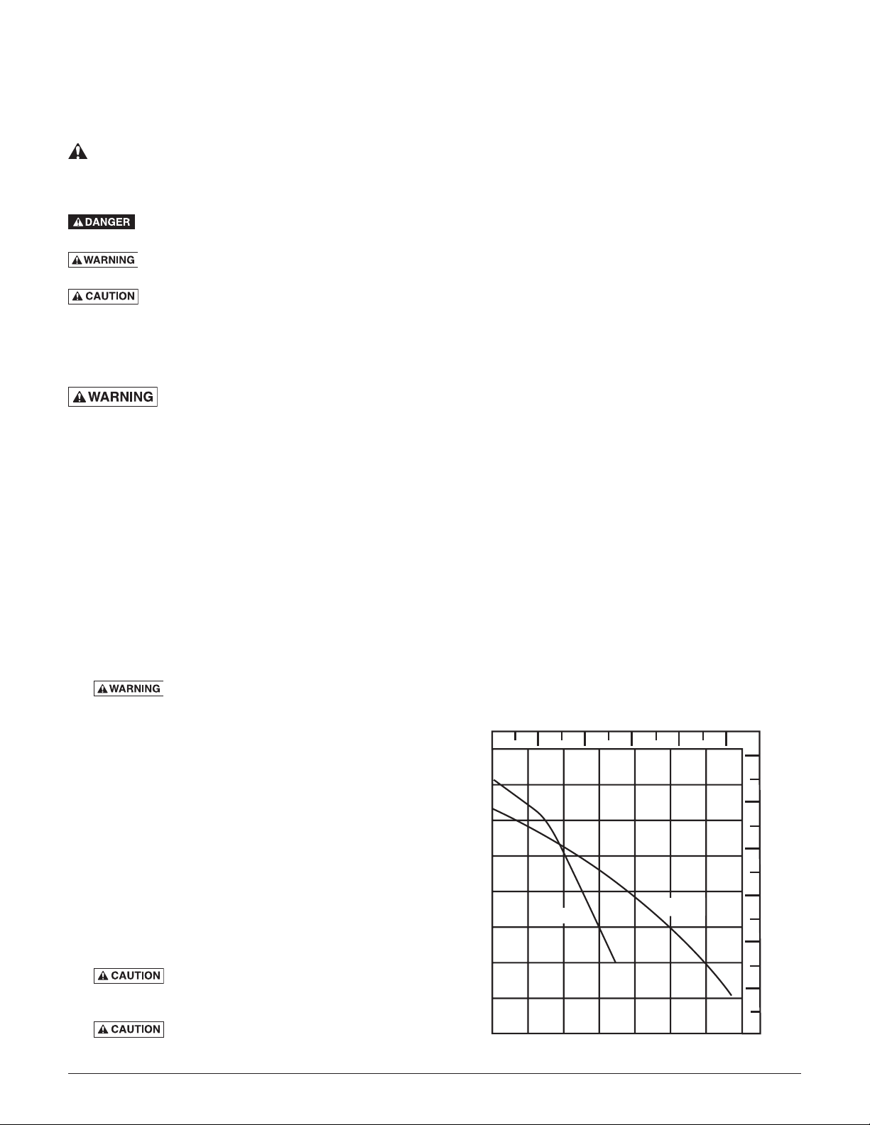
Liters per Minute
Gallons per Minute
Total Head in Feet
Total Head in Meters
SAVE THESE INSTRUCTIONS - This manual contains
important instructions that should be followed during
installation, operation, and maintenance of the product.
Save this manual for future reference.
This is the safety alert symbol. When you see this
symbol on your pump or in this manual, look for one of
the following signal words and be alert to the potential
9. The pump is permanently lubricated. No oiling
or greasing is required in normal operation. for
overhaul, see instructions under Service.
When used in effluent dosing or S.T.E.P. applications,
the pump must be installed in a separate tank or
compartment at the discharge side of the septic tank.
NOTICE Never install the pump in the main tank where
sludge collects. Do not use the pump for raw sewage.
for personal injury!
indicates a hazard which, if not avoided, will
result in death or serious injury.
indicates a hazard which, if not avoided,
could result in death or serious injury.
indicates a hazard which, if not avoided,
could result in minor or moderate injury.
NOTICE addresses practices not related to
personalinjury.
CALIFORNIA PROPOSITION 65 WARNING:
This product and related accessories
contain chemicals known to the State of California to
cause cancer, birth defects or other reproductive harm.
Carefully read and follow all safety instructions in this
manual and on pump.
Keep safety labels in good condition. Replace missing or
damaged safety labels.
1. Read these rules and instructions carefully. Failure to
follow them could cause serious bodily injury and/or
property damage.
2. Check your local codes before installing. You must
comply with their rules.
3. Vent sewage or septic tank according to local codes.
4. Do not install pump in any location classified as
hazardous by National Electrical Code, ANSI/NFPA
80-1984 or the Canadian Electrical Code.
Risk of electric shock. Can shock, burn
Description
This submersible / effluent pump is designed for effluent
dosing, Septic Tank Effluent Pumping (S.T.E.P.) and
wastewater removal, sump drainage, dewatering and
flood control. Units have built in thermal overload
protection with automatic reset. The mechanical seal
and sleeve bearings on the motor shaft are permanently
lubricated. Stainless steel hardware and a heavy duty lift
out handle allow for easy disassembly after extendeduse.
NOTICE This unit is not designed for applications
involving salt water or brine! Use with salt water or brine
will void warranty.
NOTICE This pump is not approved for, and should not
be used in, swimming pools or fountains.
Specifications
Power Supply ..............See Table 1 Motor Specifications
Maximum Liquid Temperature................ 120° F (49°C)
Discharge Adapter...........................1-1/2” NPT
Maximum Solids Handling ..........................3/4”
Motor Type ............................... Shaded Pole
RPM ..........................................1550
Motor Insulation ............................... Class A
Overload Protection ...........Internal with Automatic Reset
Bearings ................................Double Sleeve
Starting Switch Required ...........................None
Control Panel Required ............................None
Performance
or kill. During operation the pump is in water.
To avoid fatal shocks, proceed as follows if pump
050
100 150 200 250
needsservicing:
Do not smoke or use devices that can generate
sparks in a septic (gaseous) environment.
5A. Disconnect power to outlet box before
unpluggingpump.
40
35
30
12
10
5B. Take extreme care when changing fuses. Do not
stand in water or put your finger in the fuse socket.
25
8
5C. Do not modify the cord and plug. When using the
cord and plug, plug into a grounded outlet only.
When wiring to a system control, connect the pump
ground lead to the system ground.
6. Be sure that construction and access to septic sumps
conform with all OSHA requirements.
20
15
10
ME3H
ME3F
6
4
7. Risk of burns. Do not run the pump dry.
Dry running can overheat the pump, (causing burns
5
2
to anyone handling it) and will void the warranty.
8. Risk of burns. The pump normally runs
hot. To avoid burns when servicing pump, allow it to
0
0
10 20 30 40 50
60 70
0
cool for 20 minutes after shutdown before handling.
2
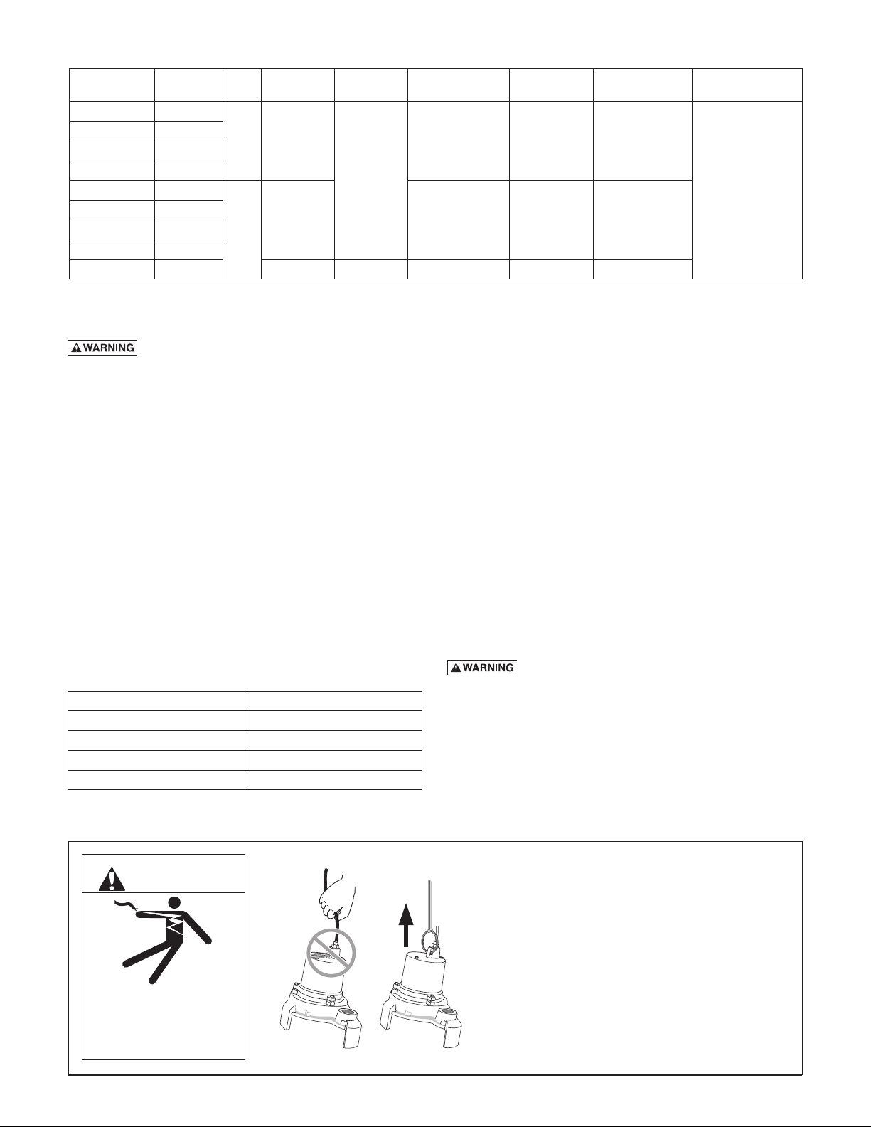
Table 1: Motor Specifications
Model Number Pump Type HP Volts/Hz/Ph Cord Length
ME3H-11 Manual
ME3F-11 Manual
ME3H-11P Auto
ME3F-11P Auto
ME3H-21 Manual
ME3F-21 Manual
ME3H-21P Auto
ME3F-21P Auto
ME3F-11P-30 Auto 115/60/1 30’ 1.2 12.0 16.0
1/3 115/60/1
1/3
230/60/1 4.3 6.0 8.2
20’
Winding Branch
Resistance In Ohms
1.2 12.0 16.0
Max. Amps. Locked Rotor Amps Circuit Req’d (Amps)
15
Installation
Risk of electric shock. Can shock, burn or
kill. Do not lift pump by the power cord. See Cord Lift
Warning below.
NOTICE Install the pump on a hard, level surface
(cement, asphalt, etc.). Never place the pump directly on
earth, clay or gravel surfaces. Install the pump in a sump
basin with a minimum diameter of 18” (46cm).
Piping
Piping must not be smaller than pump discharge.
The pump is designed to operate partially or completely
submerged in effluent liquids and pump semi-solid fluids
up to 3/4” (51mm) in diameter.
When installed in an effluent system, the pipe must be
capable of handling semi-solids of at least 3/4” (19mm)
in diameter.
The rate of flow in the discharge pipe must keep any
solids present in suspension in the fluid. To meet
minimum flow requirements (2 feet per second in the
discharge line), size the pipe as follows:
A Pipe Size Of: Will Handle a Flow Rate Of:
1-1/2” (38mm) 12 GPM
2” (51mm) 21 GPM
2-1/2” (64mm) 30 GPM
3” (76mm) 48 GPM
In an effluent system use a 1-1/2” (38mm) check valve in
pump discharge to prevent backflow of liquid into sump
basin. The check valve should be a free flow valve that
will easily pass solids. Be sure check valve installation
complies with local codes.
Be sure that the float switch hangs freely. It should not be
able to come in contact with the sides or bottom of the
sump pit.
Make sure the sump pit is free of any debris that could
obstruct the intake volute or switch.
Use plumbing materials that are approved by local
building codes when connecting pipes between pump
and sewer outlet.
NOTICE For critical indoor installations where additional
high water protection is desired, install an audible alarm
system in the sump pit. For outdoor installations, confer
with your distributor.
Connect the power cord to a 3-prong grounded
ACreceptacle.
Risk of electric shock. Can shock, burn
or kill. DO NOT remove the grounding pin from the
power cord. Avoid using extension cords or 2-prong
adapterplugs.
Insert the piggyback plug that comes from the float
switch directly into the power receptacle.
Insert the pump power cord directly into the back of the
switch’s piggyback plug/receptacle.
WARNING
Risk of electrical shock.
Can burn or kill.
Do not lift pump by power
cord.
Cord Lift Warning
1. Attempting to lift or support pump by power
cord can damage cord and cord connections.
2. Cord may pull apart, exposing bare wires with
possibility of fire or electrical shock.
3. Lifting or supporting pump by power cord will
void warranty.
4. Use lifting ring or handle on top of pump for
all lifting/lowering of pump. Disconnect power
to pump before doing any work on pump or
attempting to remove pump from sump.
3

Test the pump installation by filling the sump basin with
enough water to activate the pump and repeat this cycle
until satisfied with pump operation.
NOTICE For best performance of check valve when
handling solids, do not install it with the discharge more
than 45° above the horizontal. Do not install the check
valve in a vertical position as solids may settle in the
valve and prevent it from opening on startup.
Drill a 1/8” (3mm) hole in the discharge pipe below the
check valve to prevent airlocking the pump.
Electrical
Risk of electric shock. Can shock, burn or
kill. When installing, operating, or servicing this pump,
follow the safety instructions listed below.
1. DO NOT splice the electrical power cord.
2. DO NOT allow the plug on the end of the electrical
cord to be submerged.
3. DO NOT use extension cords. They are a fire hazard
and can reduce voltage sufficiently to prevent
pumping and/or damage motor.
4. DO NOT handle or service the pump while it is
connected to the power supply.
5. DO NOT remove the grounding prong from the
plug or modify the plug. To protect against electrical
shock, the power cord is a three-wire conductor and
includes a 3-prong grounded plug. Plug the pump
into a 3-wire, grounded, grounding-type receptacle.
Connect the pump according to the NEC or CEC and
local codes.
Automatic models are equipped with a 20’ mechanical
(mercury free), piggy-back float switch tethered directly
to the pump. The switch can also be mounted on the
discharge pipe, with a minimum 4” tether length. The
switch must float free from the pump and the basin
wall. Tape or cable-tie the cord to the discharge pipe
every 12”. Plug the switch into a properly grounded,
grounding-type receptacle of the correct voltage.
The receptacle must be installed according to all
applicablecodes.
On all duplex units or simplex units with additional
options such as a high water alarm, cut off the power
cord plug and wire the pump into a control panel (or
sealed junction box if it is installed in a wet sump or
basin). The AWS-1 control also acts as a sealed junction
box for connecting the power cord to the pump cord.
Connect or wire pump to its own individual branch
circuit with no other outlets or equipment in the
circuit. Size fuses or circuit breakers according to
Table 1, Motor Specifications.
Risk of fire and explosion. Can cause severe
injury, property damage or death. Be sure that power
supply information (Voltage/ Hertz/Phase) on pump
motor nameplate matches incoming power supply
exactly. Install pump according to all electrical codes
that apply.
Operation
Risk of fire and explosion. Can cause
severe injury, property damage or death. Do not use in
explosive atmospheres. Pump water only with this pump.
NOTICE Do not allow the pump to run in a dry sump. It
will void the warranty and may damage the pump.
An automatic overload protector in the motor will
protect the motor from burning out due to overheating/
overloading. When the motor cools down, the overload
protector will automatically reset and start the motor.
If the overload trips frequently, check for the cause.
It could be a stuck impeller, wrong/low voltage, or
an electrical failure in the motor. If an electrical
failure in the motor is suspected, have it serviced by a
competentrepairman.
The pump is permanently lubricated. No oiling or
greasing is required.
Cycle the pump at least once every month to be sure that
the system is working satisfactorily.
NOTICE Any of the following will void the
pumpwarranty:
1. Submerging, plugging, damaging or taping shut a
vented cord.
2. Pumping materials other than those the pump was
designed to pump or continuously pumping water
hotter than 120°F (49°C).
3. Cutting or splicing a power cord or switch cord.
4. Removing the cord tag from the cord.
Service
General
Risk of electric shock. Can shock, burn
or kill. Before removing the pump from the basin for
service, always disconnect electrical power to the pump
and the control switch. Do not lift the pump by the
power cord. See the Cord Lift Warning.
Disinfect the Pump
Place the pump in an area where it can be cleaned
thoroughly. Remove all scale and deposits on the pump.
Risk of infection. Submerge the complete
pump in a disinfectant solution (dilute chlorine bleach)
for at least one hour before disassembling the pump.
The pump motor housing contains a special lubricating
oil which should be kept clean and free of water at
alltimes.
NOTICE Whenever the motor housing is being removed
for service, remove oil and replace it with new oil at
reassembly. Use only oil listed in parts list in this manual.
When filling with new oil, DO NOT overfill. Be sure that
the oil level is 3/4” below the top of the cover.
4
 Loading...