

MYERS MCI033, MCI050 Owner's Manual
© 2008 MY840 (Rev. 9/10/09)
1101 Myers Parkway
Ashland, OH 44805
Phone:
1-888-987-8677
Fax:
1-800-426-9446
Web Site:
http://www.myerspump.com
5869 0808
MCI033, MCI050
Installation/Operation/Parts
For further operating, installation,
or maintenance assistance:
Call 1-888-987-8677
English . . . . . . . . . . . . . . . Pages 2-6
Installation/Fonctionnement/Pièces
Pour plus de renseignements
concernant l’utilisation,
l’installation ou l’entretien,
Composer le
1 (519) 748-5470
Français . . . . . . . . . . . . Pages 7-11
Instalación/Operación/Piezas
Para mayor información sobre el
funcionamiento, instalación o
mantenimiento de la bomba:
Llame al 1-888-987-8677
Español . . . . . . . . . . .Paginas 12-16
OWNER’S MANUAL
Submersible Sump/
Effluent Pump
NOTICE D’UTILISATION
Pompe de puisard/
d’effluents submersible
MANUAL DEL USUARIO
Bomba de sumidero/
efluente sumergible
SAFETY INFORMATION
Carefully read and follow all safety instructions in this
manual or on pump.
This is the safety alert symbol. When you see this
symbol on your pump or in this manual, look for one of the
following signal words and be alert to the potential for
personal injury!
warns about hazards that will cause serious
personal injury, death or major property damage if ignored.
warns about hazards that can cause serious
personal injury, death or major property damage if ignored.
warns about hazards that will or can cause
minor personal injury or property damage if ignored.
The word NOTICE indicates special instructions which are
important but not related to hazards.
DESCRIPTION
These Submersible Sump Pumps are designed for home
sumps. The unit is equipped with a 3-prong grounding-type
power cord. The shaded-pole motor is oil filled and sealed for
cooler running. Upper sleeve/lower ballbearing on the motor
shaft never need lubrication. Automatic reset thermal
protection.
SPECIFICATIONS
Power supply required........................................115V, 60 HZ.
Liquid Temp. Range..........................32°F to 130°F (0°-54°C)
Individual Branch Circuit Required:...........................15 Amps
Discharge ..............................................................1-1/2" NPT
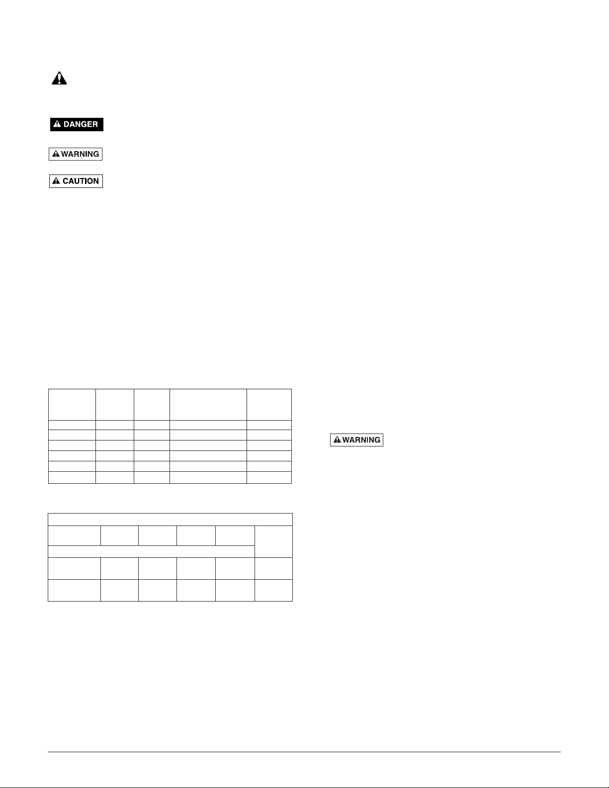
PERFORMANCE
GENERAL SAFETY INFORMATION
Electrically powered sump pumps normally give many years
of trouble-free service when correctly installed, maintained,
and used. However, unusual circumstances (interruption of
power to the pump, dirt/debris in the sump, flooding that
exceeds the pump’s capacity, electrical or mechanical failure
in the pump, etc.) may prevent your pump from functioning
normally. To prevent possible water damage due to flooding,
consult your dealer about installing a secondary sump pump,
a DC backup sump pump, and/or a high water alarm. See the
“Troubleshooting Chart” in this manual for information about
common sump pump problems and remedies. For more information, see your dealer.
1. Know the pump application, limitations, and potential
hazards.
2. Disconnect the power before servicing.
3. Release all pressure within the system before servicing
any component.
4. Drain all water from the system before servicing.
5. Secure the discharge line before starting the pump. An
unsecured discharge line will whip, possibly causing personal injury and/or property damage.
6. Check the hoses for a weak or worn condition before
each use. Make certain all connections are secure.
7. Periodically inspect the sump, pump and system components. Keep free of debris and foreign objects. Perform
routine maintenance as required.
8. Provide a means of pressure relief for pumps whose discharge line can be shut-off or obstructed.
9. Personal Safety:
a. Wear safety glasses at all times when working with
pumps.
b. Keep the work area clean, uncluttered and properly
lighted – replace all unused tools and equipment.
c. Keep visitors at a safe distance from work area.
d. Make the workshop child-proof – with padlocks, mas-
ter switches, and by removing starter keys.
10. When wiring an electrically driven pump, follow all electrical and safety codes that apply.
11. This equipment is only for use on 115 volt (single
phase) and is equipped with an approved 3-conductor cord and 3-prong, grounding-type plug.
Electrical shock hazard. Can burn or
kill. To reduce risk of electric shock, pull plug before ser-
vicing. Pump is supplied with a grounding conductor and
grounding-type attachment plug. Be sure it is connected
only to a properly grounded grounding-type receptacle.
Where a 2-prong wall receptacle is encountered, it must
be replaced with a properly grounded 3-prong receptacle
installed in accordance with codes and ordinances that
apply.
This pump has not been investigated for use in swimming pool areas.
12. All wiring should be performed by a qualified electrician.
13. Make certain the power source conforms to the requirements of your equipment.
14. Protect the electrical cord from sharp objects, hot surfaces, oil, and chemicals. Avoid kinking the cord. Replace
or repair damaged or worn cords immediately.
15. Do not touch an operating motor. Motors can operate at
high temperatures.
16. Do not handle the pump or pump motor with wet hands
or when standing on wet or damp surface, or in water.
2
GPM (LPM) AT TOTAL FEET (m)
5101520
Model (1.5m) (3m) (4.6m) (6.1m)
CAPACITY GALLONS(L)/MINUTE
MCI033
48 40 29 15 24 Ft.
(182) (151) (110) (57) (7.3m)
MCI050
62 52 45 39 32 Ft.
(235) (197) (170) (148) (9.8m)
No flow
at height
shown
below
Full Individual
Model Motor Load Branch Circuit Cord
Number HP Amps Required (Amps) Length
MCI033 1/3 9.8 15 10’
MCI033-20 1/3 9.8 15 20’
MCI033-30 1/3 9.8 15 30’
MCI050 1/2 12.0 15 10’
MCI050-20 1/2 12.0 15 20’
MCI050-30 1/2 12.0 15 30’
MOTOR & CORD SPECIFICATIONS

Electrical shock hazard. Can burn or kill. If
your basement has water or moisture on floor, do not walk on
wet area until all power has been turned off. If shut-off box is
in basement, call electric company or hydro authority to shutoff service to house, or call your local fire department for
instructions. Remove pump and repair or replace. Failure to
follow this warning can result in fatal electrical shock.
17. Pump water only with this pump. Do not use with salt
water or brine.
18. Do not install the pump in any location classified as
hazardous by the National Electric Code, ANSI/NFPA
70-1984 or the Canadian Electrical Code.
INSTALLATION
1. Install the pump in a sump pit with a minimum diameter
of 11" (279mm). The sump depth should be 15" minimum
(381mm). Construct the sump pit of tile, concrete, steel
or plastic. Check the local codes for approved materials.
2. Adjust the float stop on the rod to adjust the pump “ON”
point. “OFF” point is factory preset.
3. The pump should not be installed on clay, earth or sand surfaces. Clean the sump pit of small stones and gravel which
could clog the pump. Keep the pump inlet screen clear.
4. Install the pump in the pit so that the switch operating
mechanism has maximum possible clearance.
5. Install the discharge plumbing. When using rigid pipe,
use plastic pipe. Wrap the threads with Teflon tape
TM
.
Screw the pipe into the pump hand tight plus 1 to 1-1/2
turns.
NOTICE: Do not use ordinary pipe joint compound on
plastic pipe. Pipe joint compound can attack plastics and
damage the pump.
Risk of flooding. If a flexible discharge
hose is used, make sure the pump is secure in the sump
to prevent movement. Failure to secure the pump may
allow pump movement, switch interference and prevent
the pump from starting or stopping.
6. To reduce motor noise and vibrations, a short length of
rubber hose (e.g. radiator hose) can be connected into
the discharge line near the pump using suitable clamps.
7. Install an in-line check valve to prevent backward flow
through the pump when the pump shuts off.
8. Power Supply: The pump is designed for 115 V., 60 Hz.,
operation and requires a minimum 15 amp individual
branch circuit. The pump is supplied with a 3-wire cord
set with grounding-type plug. Do not modify cord or plug.
Be sure it is connected only to a properly grounded
grounding-type receptacle.
Hazardous voltage. Can shock, burn or
kill. The pump should always be electrically grounded to
a suitable electrical ground such as a grounded water
pipe or a properly grounded metallic raceway, or ground
wire system. Do not modify the cord or plug or cut off the
round ground pin.
9. If the pump discharge line is exposed to an outside subfreezing atmosphere, the portion of the line exposed
must be installed so any water remaining in the pipe will
drain to the outfall by gravity. Failure to do this can cause
the water trapped in the discharge to freeze which could
result in damage to the pump.
10. After the piping and check valve have been installed, the
unit is ready for operation.
11. Check the operation by filling the sump with water and
observing pump operation through one complete cycle.
Risk of Flooding. Failure to make this
operational check may lead to improper operation, premature failure, and flooding.
OPERATION / MAINTENANCE
Risk of electrical shock. Can burn or cause
death. Do not handle a pump or pump motor with wet hands
or when standing on a wet or damp surface, or in water.
Before attempting to check why unit has stopped operating,
disconnect power from unit.
Risk of fire and explosion. Can cause
severe injury, property damage or death. Do not use in
explosive atmospheres. Pump water only with this pump.
1. The shaft seal depends on water for lubrication and cooling. Do not operate the pump unless it is submerged in
water as the seal may be damaged if allowed to run dry.
2. The motor is equipped with an automatic reset thermal
protector. If the temperature in the motor should rise
unduly, the switch will cut off all power before damage
can be done to the motor. When the motor has cooled
sufficiently, the switch will reset automatically and restart
the motor. If the protector trips repeatedly, the pump
should be removed and checked as to cause of difficulty.
Low voltage, long extension cords, clogged impeller, very
low head or lift, etc., could cause cycling.
3. The pump will not remove all water. If a pump is operating
and suddenly no water comes out of the discharge hose,
shut the unit off immediately. The water level is probably
very low and the unit has broken prime.
SWITCH REPLACEMENT
1. Disconnect power to the pump.
2. Remove the pump from the sump. If it is in effluent service, disinfect it for one hour with chlorine bleach. Wear
rubber gloves when handling the pump.
3. Remove the bottom tether strap from the float rod, lift
the float and swing it sideways, and remove it from the
switch arm.
4. Remove the four screws that secure the switch to the top
of the motor housing and lift the switch off the motor. The
switch guard may come off with it.
5. Disconnect four wires that connect the switch to the motor
housing.
6. Remove and discard the gasket between the switch and
the pump. Clean the gasket surface on the motor housing.
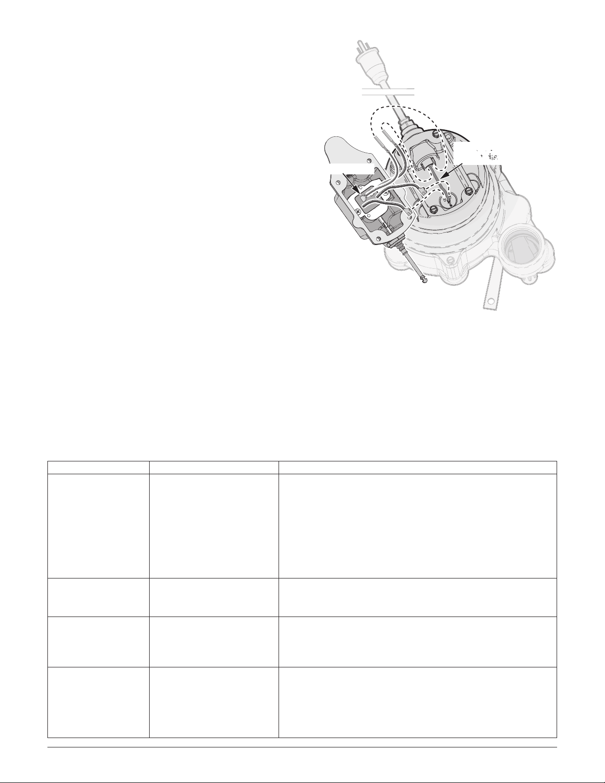
7. Set the new gasket on the motor housing, then connect
the four wires on the new switch to the four terminals in
the motor housing (see Figure 1, page 4). Do not disturb
the two spade terminals on the switch!
NOTE: When you connect the two power wires to the
cord terminals, make sure that the wire ends don’t lodge
between the cord pin and the side of the cord plug. The
connector must be on the pin.
8. With the switch guard in place, set the switch on the
motor housing with the switch arm pointed toward the discharge side of the pump and install and tighten the four
screws which secure the switch to the pump.
3
TM
E.I. DuPont de Nemours and Company Corporation.
4
SYMPTOM PROBABLE CAUSE(S) CORRECTIVE ACTION
Pump won’t start Blown fuse. If blown, replace with a fuse of proper size.
or run. Low line voltage. If the voltage is under the recommended minimum, check the size
of the wiring from the main switch on the property. If OK, contact
power company or hydro authority.
Defective motor. Replace the pump.
Defective float switch. Replace the float switch.
Impeller. If the impeller won’t turn, remove the lower pump body and locate
the source of the binding.
Float is obstructed. Remove the obstruction.
Pump starts and stops Backflow of water from Install or replace the check valve.
too often. piping.
Faulty float switch. Replace the float switch.
Pump won’t shut off. Defective float switch. Replace the float switch.
Restricted discharge Remove the pump and clean the pump and piping.
(obstacle in piping).
Float obstructed. Remove the obstruction.
Pump operates but Low line voltage. If the voltage is under the recommended minimum, check the size
delivers little or no of the wiring from the main switch on the property. If OK, contact
water. power company or hydro authority.
Something is caught in Clean out the impeller.
impeller.
Anti-airlock hole is plugged. Turn off the pump, clean out the anti-airlock hole, and restart pump.
TROUBLESHOOTING CHART
9. Holding the float out sideways, hook the float rod on to
the switch arm and swing the float rod down.
10. Insert the float rod in the hole in the tether strap.
11. Reinstall the pump in the sump, check all piping connections, and reconnect the power. Run the pump through
one complete operating cycle to check for proper operation. Failure to make this operational check may lead to
flooding and will void the warranty.
AIRLOCKS
When a pump airlocks, it runs but does not move any water.
An airlock will cause the pump to overheat and fail.These
pumps have a built in anti-airlock hole. See the exploded
view on the repair parts page for the location of the hole.
Leakage from the anti-airlock hole is normal.
If you suspect an airlock, unplug the pump, clean out the
anti-airlock hole with a paper clip or a piece of wire, and
restart the pump.
Figure 1: Connect switch as shown. Do not disturb the spade
terminals on the switch. The gasket has been omitted for
clarity.
Ground Wire –
Do not disturb!
Do not disturb!
5887 1008
* If motor fails, replace entire pump.
5
MCI033
MCI050
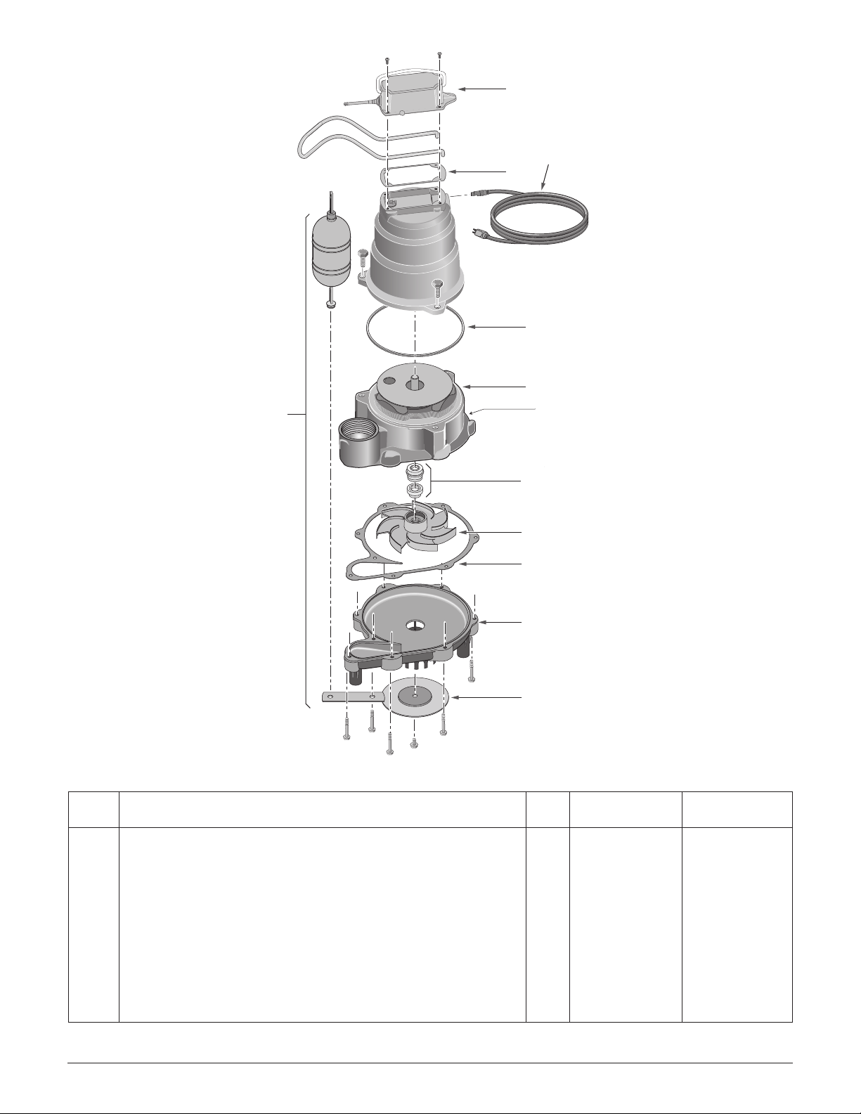
REPAIR PARTS
Key
No. Description Qty. MCI033 MCI050
1 Switch Kit 1 PS17-1550REP PS17-1550REP
2 Gasket Kit (Includes O-Rings and Gaskets, Key Nos. 2A,2B, 2C) 1 U9-471REP U9-471REP
3 Power Cord 10’ 1 PW117-237-TSU PW117-237-TSU
Power Cord 20’ 1 PW17-122 PW17-122
Power Cord 30’ 1 PW17-293 PW17-293
4 Motor 1 * *
5 Shaft Seal 1 21607A001 21607A001
6 Impeller 1 PS5-26P PS5-29P
7 Lower Volute 1 PS1-34P PS1-34P
8 Suction Plate 1 U43-142SS U43-142SS
9 Switch Float Kit (Includes Float, Switch Rod, Rod Stops and 1 PS28-37REP PS28-37REP
Tether Strap)
1
3
2A
2B
4
9
anti-airlock hole
5
6
2C
7
8
5868 0808
 Loading...