

MYERS Illuminator System CM Installation Manual

Illuminator
Series CM
.5 kW – 2.0 kW
™
System
Installation Guide
44 South Commerce Way, Bethlehem, PA 18017
1-800-526-5088 • (610) 868-3500 • Fax: (610) 868-8686
Service: (610) 868-5400
www.myerseps.com
113903G –System Installation Manual

1
This unit contains LETHAL VOLTAGES. All repairs and service should be performed by
AUTHORIZED SERVICE PERSONNEL ONLY! There are NO USER SERVICEABLE
PARTS inside this unit.
IMPORTANT SAFEGUARDS
When using electrical equipment, you should always follow basic safety
precautions, including the following:
1. READ AND FOLLOW ALL SAFETY
INSTRUCTIONS.
2. Do not install the system outdoors.
3. Do not install near gas or electric heaters or in other high-temperature
locations.
4. Use caution when servicing batteries. Depending on battery type, batteries
contain either acid or alkali and can cause burns to skin and eyes. If
battery fluid is spilled on skin or in the eyes, flush with fresh water and
contact a physician immediately.
5. Equipment should be mounted in locations where unauthorized personnel
will not readily subject it to tampering.
6. The use of accessory equipment not recommended by Manufacturer may
cause an unsafe condition and void the warranty.
7. Do not use this equipment for other than its intended use.
8. Qualified service personnel must perform all servicing of this equipment.
SAVE THESE INSTRUCTIONS
The installation and use of this product must comply with all national, federal,
state, municipal, or local codes that apply. If you need help, please call
Service at 1-610-868-5400.
113903G -System Installation Manual

2
C A U T I O N
READ ENTIRE MANUAL AND REVIEW ALL DOCUMENTATION BEFORE ATTEMPTING SYSTEM
INSTALLATION!
FOR SERVICE OR INSTALLATION INFORMATION:
TELEPHONE: (610) 868-5400 (24 HR. HOTLINE)
FAX: (610) 954-8227
FOR YOUR PROTECTION....
PLEASE COMPLETE AND RETURN WARRANTY REGISTRATION CARD IMMEDIATELY.
113903G -System Installation Manual

3
C H A P T E R 1
SAFETY WARNINGS
Read the following precautions before you install the Illuminator Series C-M.
IMPORTANT SAFETY INSTRUCTIONS
SAVE THESE INSTRUCTIONS. This manual contains important instructions that you should
follow during installation and maintenance of the system and batteries. Please read all instructions
before operating the equipment and save this manual for future reference.
DANGER
This system contains LETHAL VOLTAGES. AUTHORIZED SERVICE PERSONNEL should
perform all repairs and service ONLY. There is NO USER SERVICEABLE PARTS inside.
WARNING
• Do not install the system outdoors.
• Do not install near gas or electric heaters or in other high-temperature locations.
• Use caution when servicing batteries. Battery acid can cause burns to skin and eyes. If acid is
spilled on skin or in the eyes, flush with fresh water and contact a physician immediately.
• Equipment should be mounted in locations where it is not readily subjected to tampering by
unauthorized personnel.
• The use of accessory equipment not recommended by the manufacturer may cause an unsafe
condition.
• Do not use this equipment for other than intended use.
• Only qualified service personnel (such as a licensed electrician) should perform the system and
battery installation and initial startup. Risk of electrical shock.
113903G -System Installation Manual

4
C H A P T E R 2
INTRODUCTION
Please read this manual thoroughly before operating your safety system. Keep this manual and
the system User’s Guide.
WARNING
Only qualified service personnel (such as a licensed electrician) should perform the system
and battery installation and initial startup. Risk of electrical shock.
Please record your unit’s model number, serial number, and part number below. You can find
these numbers on the label on the inside of the system’s circuit breaker door.
Model Number __________________________
Serial Number __________________________
Part Number __________________________
113903G -System Installation Manual

5
C H A P T E R 3
BEFORE INSTALLING THE UNIT
Installation Dimensions
INVERTER MODULE DIMENSIONS – 10” X 10” X 26”
INVERTER MODULE WITH BATTERY MODULE DIMENSIONS
UNIT SIZE WIDTH HEIGHT DEPTH
500 26” 20” 10”
1000 26” 30” 10”
1500 26” 40” 10”
2000 26” 50” 10”
113903G -System Installation Manual

6
Location Guidelines
500W
1000W
1500W
2000W
Battery
Inverter
System
Keep the following guidelines in mind when choosing the location for your system and batteries:
• Verify that the environment meets the requirements in “Storage and Operating Environment” on
page 7. The environment can affect the reliability and performance of both the unit and the
batteries.
• Install any separate battery cabinets as close as possible to the unit to reduce the cost of DC
wiring and to improve battery performance. We recommend no clearance between the unit and
the battery cabinet; in other words, the battery cabinet(s) should be directly under or to the left
side of the unit (when you face the front of the unit). If you must place the battery cabinet away
from the unit, you must supply the proper length, gauge, and type of battery cables, and you must
make sure the installation meets the applicable NEC (CEC) requirements.
• Choose a permanent location for the unit and any battery cabinets. Attempting to move them after
you have installed the batteries can damage the batteries and the cabinet.
CAUTION
Do not move the unit or the battery cabinet after you install the batteries. If you do, the unit or
battery cabinet and batteries may be damaged.
CEC (Canadian Electric Code) requires the unit to be located in a service room. If the room is
equipped with a sprinkler system, the unit must be provided with sprinkler proof covers.
The system should be connected to the emergency generator, if available.
This equipment is heavy. Refer to Table 3.4 when you choose a site to make sure that
the floor can support the weight of the system, the batteries, any separate battery
cabinets, and any other necessary equipment.
Table 3.4 System weight [in lbs. (kg)]
Cabinet
Cabinet
Batteries 108 (49) 216 (98) 324 (147) 432 (196)
Total
22 (10) 44 (20) 66 (30) 88 (40)
72 (33) 72 (33) 72 (33) 72 (33)
202 (92) 332 (151) 462 (210) 592 (269)
Receiving and Handling the Unit and the Batteries
This system can weigh several hundred pounds (see Table 3.4; ask your sales representative for
additional information). Make sure you are prepared for these weights before you unload or move the
unit or the batteries. Do not install any batteries until you have permanently installed the unit with
battery cabinets and connected all conduit and wiring.
113903G -System Installation Manual

7
Storage and Operating Environment
Make sure you store and install the system in a clean, cool, dry place with normal ventilation for
human habitation and level floors.
Storage Temperature
Store the batteries at -18 to 40°C (0 to 104°F). Batteries have a longer shelf life if they are stored
below 25°C (77°F). Keep stored batteries fully charged. Recharge the batteries every 90–120 days.
The system or battery cabinet without batteries may be stored at -20 to 70°C (-4 to 158°F).
Ventilation
The air around the unit must be clean, dust-free, and free of corrosive chemicals or other
contaminants. Do not place the system or batteries in a sealed room or container.
Operating Temperature
System can operate from 20° to 30°C (68° to 86°F) and up to 95% relative humidity. The batteries’
service life is longer if the operating temperature stays below 25°C (77°F).
Batteries
The temperature should be near 25°C (77°F) for optimum battery performance. Batteries are less
efficient at temperatures below 18°C (65°F), and high temperatures reduce battery life. Typically, at
about 35°C (95°F), battery life is half of what it would be at a normal temperature of 25°C (77°F). At
about 45°C (113°F), battery life is one-fourth of normal.
Make sure that heaters, sunlight, air conditioners, or outside air vents are not directed toward the
batteries. These conditions can make the temperature within battery strings vary, which can cause
differences in the batteries’ voltages. Eventually, these conditions affect battery performance.
Remember that the batteries should be installed as close as possible to the unit to reduce DC wiring
costs and improve battery performance.
Do not allow tobacco smoking, sparks, or flames in the system location because hydrogen is
concentrated under the vent cap of each cell of the battery. Hydrogen is highly explosive, and it is
hard to detect because it is colorless, odorless, and lighter than air.
Every type of battery can produce hydrogen gas, even sealed maintenance-free batteries. The gas is
vented through the vent caps and into the air, mainly when the unit is charging the batteries. The
batteries produce the most hydrogen when maximum voltage is present in fully charged batteries; the
batteries do not produce hydrogen during float charging. The amount of current that the charger
supplies to the batteries (not the battery ampere-hour) determines how much hydrogen is produced.
High Altitude Operation
The maximum operating ambient temperature drops 1°C per 300m (2°F per 1000 ft) above sea level.
Maximum elevation is 3000m (10,000 ft).
113903G -System Installation Manual
8
C H A P T E R 4
INSTALLATION OVERVIEW
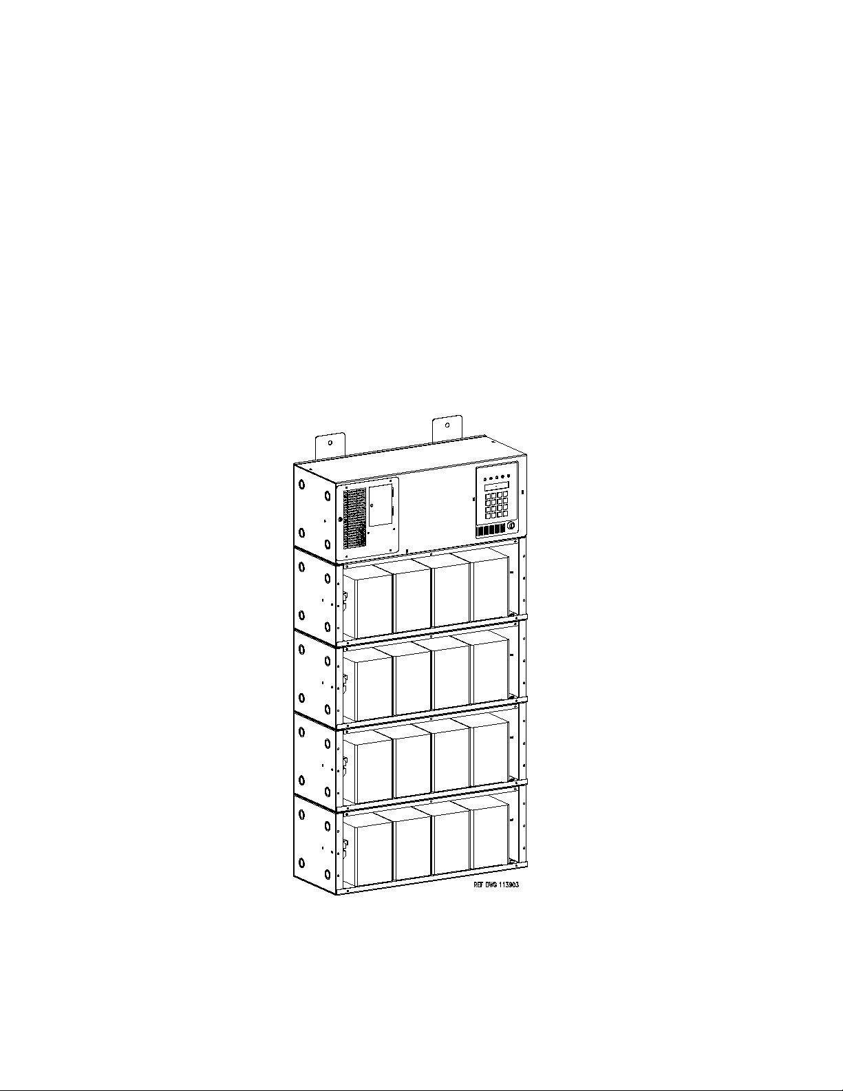
Figure 4.1 shows a typical vertical installation of the system. This drawing depicts a 2000W inverter
with battery cabinets. The Illuminator Series C-M is a modular system capable of single-phase power
outputs up to 2,000 Watts depending on the number of battery cabinets. The Inverter and Battery
modules are shipped separate and require attachment for the depicted typical vertical installation
shown in figure 4.1. All instructions included in this literature are for this type of installation.
4 x ¼-20 bolts that the user must install secure each cabinet to each other. There are Electrical
Knock- Outs in the vertical and horizontal axis to allow inter-connectivity in multiple configurations.
The Vertical installation is the most popular however; allowing the batteries to be mounted separately
and horizontally allows the user to fit this system almost anywhere where floor space is tight or not
available at all.
Figure 4.1 Typical Vertical Installation
113903G -System Installation Manual
9
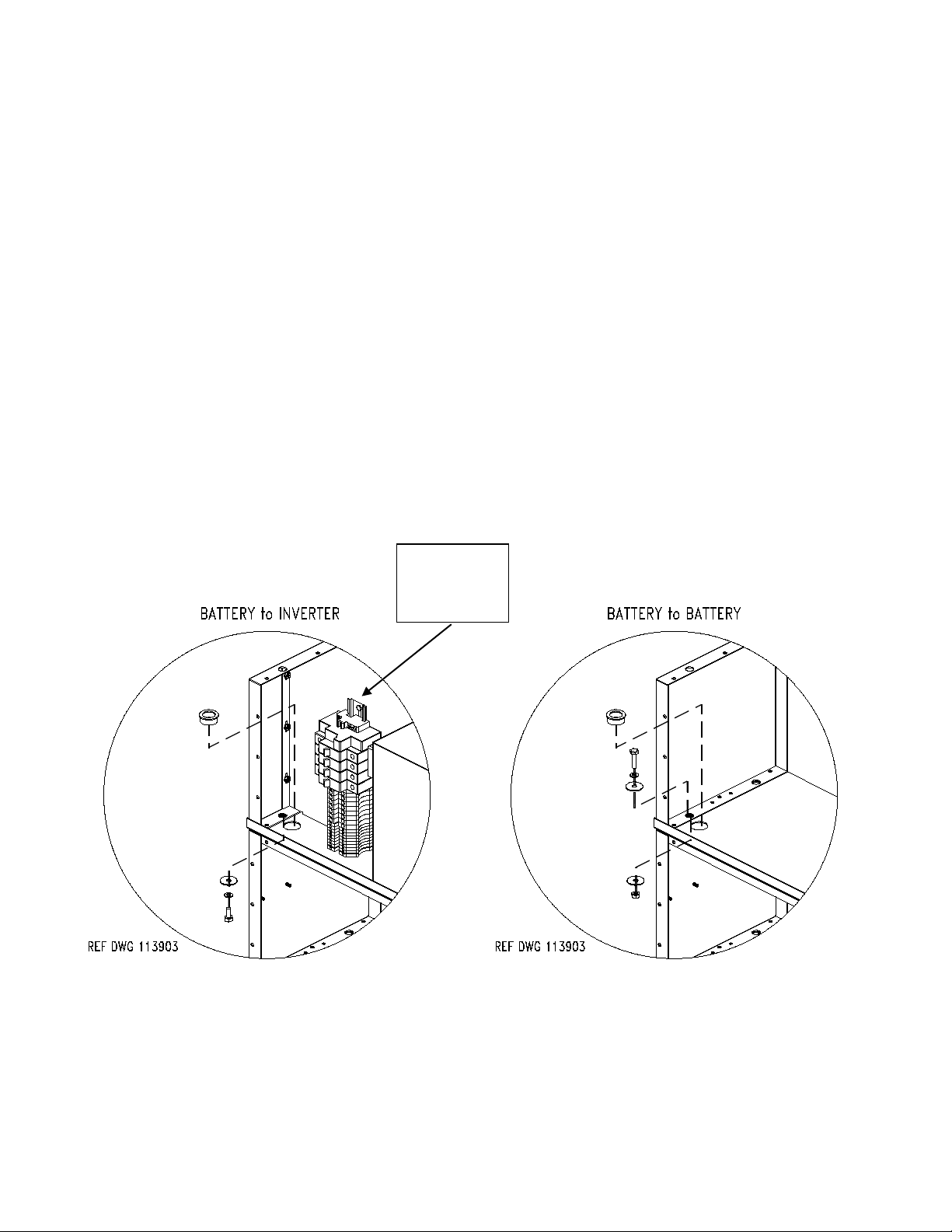
Inverter Module and Battery Module Assembly
AC/DC
Refer to Chapter 8 for Optional Wall Mounting directions.
5 x 8-32 screws located on the front and top of the module easily remove the
Inverter Module cover and 5 x 8-32 screws located on the front of the Battery
Module’s easily remove each cover. There are 4 holes located on each corner that
allow the ¼-20 hardware to attach to the different modules.
There are Electrical Knock-Outs that must be removed on the Inverter Module and
the Battery Module to allow passage of the battery cables. After the Electrical KnockOuts are removed, the factory provided plastic grommet must be inserted through
the hole to provide abrasion resistance for the wires. After the plastic grommet is
inserted, the bolts, washers and lock washers should be inserted and tightened
down. Use the plastic grommet as the alignment between the two modules. Shown
in figure 4.2 is the exploded view showing the hardware, Electrical Knock-Out and
the plastic Grommet.
Battery Module to Battery Module connections uses a plastic grommet, bolts,
washers, lock washers and nuts.
Distribution
Center
Figure 4.2
113903G -System Installation Manual
10
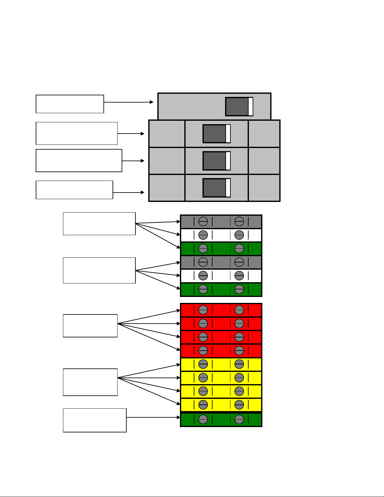
TERMINAL BLOCK/CIRCUIT BREAKER STANDARD CONFIGURATION
Input AC Line, Neutral
Output AC Line,
Ground.
Battery Positive
Battery
4 places
Fuse Block
Input Circuit Breaker CB2
Output Circuit Breaker CB3
Battery Circuit Breaker
CB1
Battery Module (s)
Series C-M Inverter Module
and Earth Ground.
Neutral and Earth
4 Places
Negative
Ground Connector
113903G -System Installation Manual

11
C H A P T E R 5
AC INPUT & AC OUTPUT INSTALLATION
WARNING
Only qualified service personnel (such as a licensed electrician) should perform the AC
installation. Risk of electrical shock.
Read the following cautions before you continue.
CAUTION
• Unit contains hazardous AC and DC voltages. Because of these voltages, a qualified
electrician must install the system, AC line service, and batteries. The electrician must
install the AC line service according to local and national codes and must be familiar
with batteries and battery installation.
• Before you install, maintain, or service the unit, always remove or shut off all sources of
AC and DC power and shut off the system. You must disconnect AC line input at the
service panel and turn off the Installation Switch (S1), the Main AC Input Circuit
Breaker (CB2), and the Battery Fuse(s) to make sure the unit does not supply output
voltage.
• Whenever AC and/or DC voltage is applied, there is AC voltage inside the unit; this is
because the unit can supply power from AC line or from its batteries. To avoid
equipment damage or personal injury, always assume that there may be voltage inside
the unit.
• Remove rings, watches, and other jewelry before installing the AC wiring. Always wear
protective clothing and eye protection and use insulated tools when working near
batteries. Whenever you are servicing an energized unit with the inside panel open,
electric shock is possible; follow all local safety codes. TEST BEFORE TOUCHING!
• To reduce the risk of fire or electric shock, install the unit and its batteries in a
temperature- and humidity-controlled indoor area free of conductive contaminants. See
page 7 for operating environment specifications.
1. Remove the Inverter Module’s cover. Make sure the installation switch and all the input
circuit breaker are off (off = left).
2. Look at the ID label inside the Inverter Module’s Circuit Breaker Access Door. Write
down the following information:
Input Voltage: __________
Output Voltage: __________
3. Now, make sure the input and output voltages are what you need. Remember that the
system provides single-phase power only.
113903G -System Installation Manual
 Loading...