

MYERS E54-30, E70-23V, E54-30L, E70-23VL, E80-20V Safety Instructions
...
CALL 1-800-577-8111 FOR SALES AND SUPPORT
E Series
Reciprocating Pump (Shaft Drive)
Safety Instructions and Service Manual
E54-30 Part No. 26866F000
E54-30L Part No. 26866F010
E70-23V Part No. 26866F100
E70-23VL Part No. 26866F110
E80-20V Part No. 26866F300
E80-20VL Part No. 26866F310
E110-14 Part No. 26866F200
E110-14L Part No. 26866F210
1
26850A003

CALL 1-800-577-8111 FOR SALES AND SUPPORT
Table of Contents
SPECIFICATIONS ............................................................................................................................... 3
DIMENSIONS ...................................................................................................................................... 4
BELT DRIVE (Dimensions) .................................................................................................................. 4
STARTING THE PUMP ........................................................................................................................ 4
SUGGESTED MAINTENANCE SCHEDULE ..................................................................................... 5
LUBRICATION ..................................................................................................................................... 5
ADDITIVES FOR CRANKCASE OIL .................................................................................................. 5
SERVICING THE PUMP:
REMOVING PISTON ...................................................................................................................... 5
INSTALLING THE PACKING ............................................................................................................ 6
REMOVING THE CYLINDERS ...................................................................................................... 6
CYLINDER INSTALLATION .......................................................................................................... 6
REMOVING THE SEATS: Wing Guided Valves ............................................................................. 6
REPLACEMENT OF VALVES ........................................................................................................ 7
REPLACING PISTON ROD SEALS .............................................................................................. 7
REMOVING CRANKSHAFT AND PINION SHAFT ...................................................................... 7
REPLACING PINION SHAFT & SHIMMING BEARINGS ............................................................ 8
REPLACING CRANKSHAFT & SHIMMING BEARINGS ............................................................. 8
RECONDITIONED CRANKSHAFTS ............................................................................................ 9
SERVICING CONNECTING LINKS .............................................................................................. 9
CROSSHEAD AND PISTON RODS ............................................................................................. 9
RECOMMENDED TORQUE (Foot-pounds) .................................................................................. 9
VALVE LIFTERS ........................................................................................................................... 10
SERVICE CHART & TROUBLE-SHOOTING ............................................................................. 11
CROSS-SECTIONAL VIEWS OF PUMPS:
SIDE VIEW – PRE JUNE 1, 2008 E70-23, E80-20 ..................................................................... 14
SIDE VIEW – POST JUNE 1, 2008 E70-23V, E80-20V ............................................................. 15
POWER-END ............................................................................................................................... 16
PARTS LIST ................................................................................................................................. 17
2
26850A003
GPM
1800 PSI
2100 PSI
2400 PSI
2700 PSI
3000 PSI
LPM
124 BAR
145 BAR
165 BAR
186 BAR
207 BAR
30 37 43 49 55 62
113 28 32 36 41 46
36 44 52 59 66 74
136 33 39 44 49 55
42 51 60 59 79 86
158 38 45 51 59 64
48 59 69 79 89 98
181 44 51 59 66 73
54 66 79 89 100 111
204 49 59 66 75 83
E-54-30
1417
1620
1823
Horsepower
/Kilowatts Required For:
RPM
1012
1215
GPM
1900 PSI 2000 PSI 2100 PSI 2200 PSI 2300 PSI
LPM
131 BAR 138 BAR 145 BAR 152 BAR 159 BAR
30 39 41 43 45 47
113 29 31 32 34 35
40 52 55 57 60 63
151 39 41 42 45 47
50 65 69 72 75 80
189 48 51 54 56 60
60 78 82 86 90 95
227 58 61 64 67 71
70 91 96 100 105 110
265 68 72 75 78 82
Horsepower
/Kilowatts Required For:
RPM
914
1143
E70-23V
1371
1600
1828
GPM
1200 PSI 1400 PSI 1600 PSI 1800 PSI 2000 PSI
LPM
83 BAR 97 BAR 110 BAR 124 BAR 138 BAR
40 33 38 44 49 55
151 24 29 33 37 41
50 41 48 55 62 69
18931364146
51
60 49 58 66 74 82
227 37 43 49 55 61
70 58 67 77 86 96
265 43 50 57 64 72
80 66 77 88 99 110
303 49 57 65 74 82
Horsepower
/Kilowatts Required For:
RPM
914
1143
E80-20V
1371
1600
1828
GPM
800 PSI
1000 PSI
1200 PSI
1400 PSI
LPM
55 BAR
69 BAR
83 BAR
97 BAR
70 38 48 58 67
265 28 36 43 50
80 44 55 66 77
302 33 41 49 57
90 49 62 74 86
340 37 46 55 64
100 55 69 82 96
378 41 51 61 72
110 60 75 90 106
416 45 56 67 79
Horsepower
/Kilowatts Required For:
E110-14
1487
1652
1817
RPM
1157
1322
E54-30 E70-23V E80-20V E110-14
RATED MAX CAPACITY (G.P.M.) 54 70 80 110
PINION SHAFT RPM @ MAX. CAPACITY 1823 1807 1828 1817
PRESSURE RATING (PSI) 3000 2300 2000 1400
CYLINDER BORE DIA. (INCHES) 1.750 2.000 2.125 2.500
PISTON STROKE LENGTH (INCHES)
GEAR REDUCTION RATIO
TEMPERATURE RATING, MAX.
SUCTION SIZE (INCHES) NOMINAL
DISCHARGE SIZE (INCHES) NOMINAL
INPUT SHAFT DIAMETER (INCHES)
KEYWAY (INCHES)
WEIGHT (Lbs.)
FLUID-END CASTING MAT'L
VALVE MAT'L
VALVE SPRING MAT'L
CYLINDER MAT'L STAINLESS STEEL/CERAMIC OXIDE COATING
525
DUCTILE IRON
17-4 PH with POLYURETHANE INSERT
STAINLESS STEEL
3" NPT
1 1/4 NPT
1.6250/1.6245
3/8 X 3/16
TRIPLEX PUMP MODELS
3.75
3.95 to 1
160F
CALL 1-800-577-8111 FOR SALES AND SUPPORT
SPECIFICA
TIONS
NOTE: Flow (GPM/LPM) based on 100% volumetric efficiency. Horsepower and kilowatts required are based on 85% overall efficiency.
Horsepower requirements are at Myers pump input shaft. The efficiency of the hydraulic pump, hydraulic motor, etc. must be considered to
determine horsepower required to drive complete system.
3
26850A003
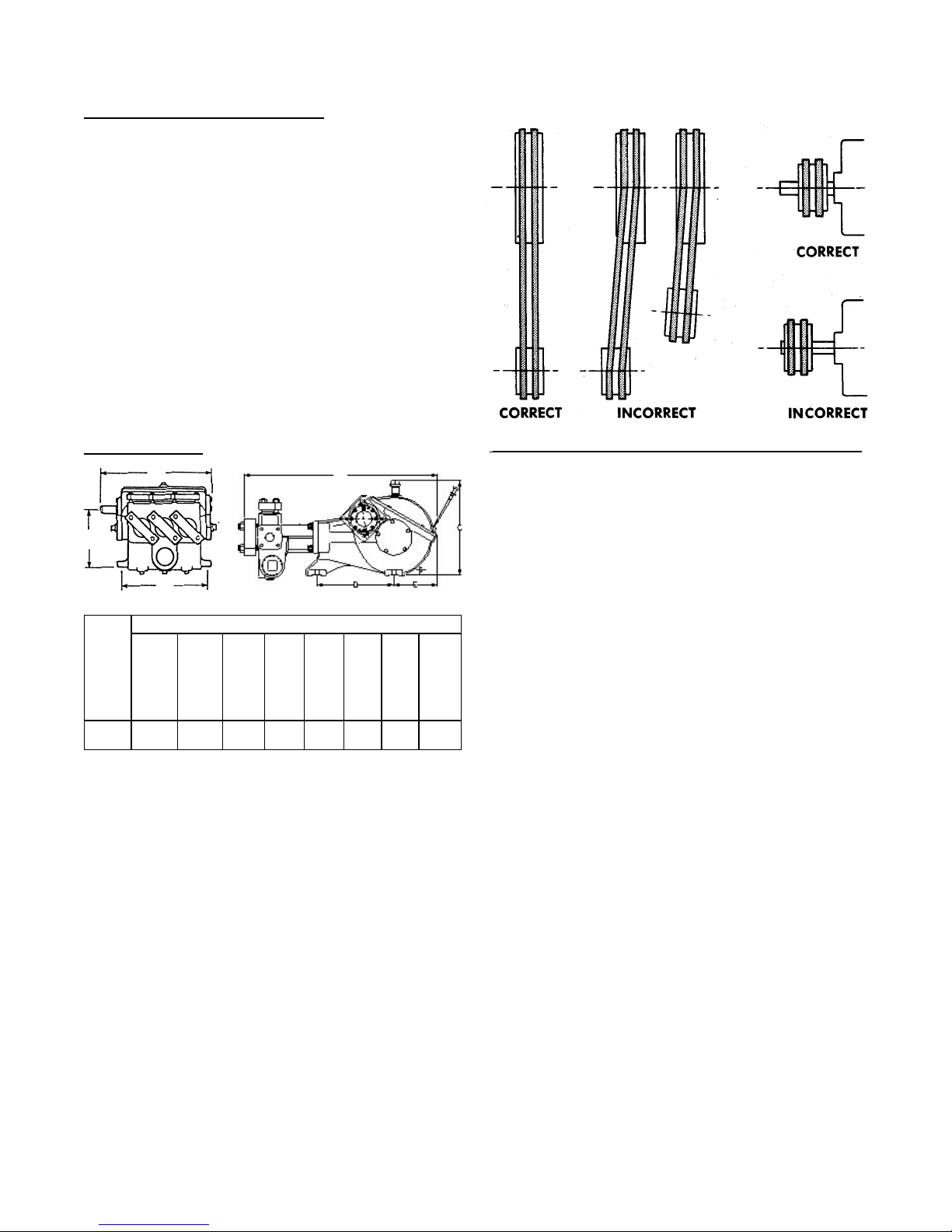
A B C D E F G
Diameter of
Mounting Hole
21 36.25 17 14 7.5 16 10.38 0.75
533.4 920.75 431.8 355.6 190.5 406.4 263.7 19.05238
Weight Lbs.
(Kg)
Dimensions in Inches
(Millimeters)
525
CALL 1-800-577-8111 FOR SALES AND SUPPORT
GENERAL INSTRUCTIONS
CAUTION: Positive Displacement Pumps must
have a proper size and operable type of pressure
regulating valve or pressure relief valve piped into
the discharge line. This is mandatory to prevent
damage to pump and piping or possible injury to
personnel. DO NOT install any valves or shut-off
devices in the bypass line from pressure regulator
to tank or supply.
DIMENSIONS
A
G
F
B
BELT DRIVE SEWER CLEANERS
With belt drives, pulley on both engine and pump should
be located as closely as possible to bearing to reduce
bearing and shaft bending loads. Make sure that all
bolts, nuts, set screws, and keys are properly tightened.
PULLEY
TION ON PUMP
LOCA
AND MOT
OR SHAFT
STARTING PUMP
A. Before Starting:
1. Read all instructions carefully.
2. Fill pump crankcase with recommended oil to
level mark on oil saber. Oil recommendations are
covered in lubrication section of pump instructions.
3. Replace all drain plugs in pump and piping.
4. Inspect tank to be sure that no foreign material is
in tank or suction line.
5. Fill tank at least half full or connect suction to
water supply. Open valve (if present) in suction
line. Avoid prolonged dry operation which may
cause excessive wear on cylinders and piston
packing. Be sure that an operating pressure
gauge is located in discharge line.
6. Make sure all valves, including spray gun or
nozzles, are open in discharge line. Spray gun
may be anchored to discharge back into tank.
7. Completely back off pressure adjusting screw on
pressure regulating valve.
B. Starting the Unit:
1. After starting, close discharge valve or spray gun
slowly while watching pressure gauge to make
sure relief valve or unloader is operating properly.
2. Adjust relief valve or unloader to desired pressure. See regulator instructions.
3. Cycle nozzles or gun on and off to be sure that
pressure adjustment and regulator operation is
satisfactory.
NOTE: Nozzle capacity should not exceed 90% of
pump capacity for satisfactory regulator operation.
AVOID FREEZING by draining all water from pump and
system in cold weather.
4
26850A003
CALL 1-800-577-8111 FOR SALES AND SUPPORT
SUGGESTED MAINTENANCE SCHEDULE
OPERATION INTERVAL
Check oil level Daily
Drain and change oil 300 hr. (1)
Replace piston packing 500 hr. (2)
Inspect valves and springs 500 hr. (3)
Inpsect connecting link bearing inserts 1000 hr. (4)
Inspect crankshaft tapered roller bearings 2000 hr.
(1) Drain at operating temperature to prevent contamina-
tion from setting.
(2) Inspect frequently for leakage; replace before 500
hours if any cylinder exceeds 10 drops per minute
leakage. Packing may not look badly worn but will
often be shiny and hard and won’t seal well.
(3) Replace if cracks and heavy wear are present.
(4) Replace at first signs of fatigue or wear to prevent
damage to crankshaft.
LUBRICATION
Fill gear case with Mobilgear 630 or equivalent 80W90
oil to capacity listed in chart. Note oil level on oil
dipstick, and maintain at this level.
NOTE: Slow speed operation of Myers Reciprocating
Pumps can be accomplished by adding additional oil to
the crankcase (see chart). The higher level compensates for lack of splash lubrication at slow speeds.
Some slight leakage may occur around crossheads and
dipstick/vent area with additional oil.
For further information, please consult the factory.
Volume of liquid MoS2 concentrate required at various speeds
VOLUME MoS2, CONCENTRATE
PINION RPM GEAR CASE OR DISPERSION “M” FOR
RANGE CAPACITY 5% 10%
1600 - 1800 6½ Qts. 7 Fl. Oz. 14 Fl. Oz.
1000 - 1599 6½ Qts. 9 Fl. Oz. 18 Fl. Oz.
600 - 999 6½ Qts. 10 Fl. Oz. 20 Fl. Oz.
The MoS2 fluid concentrate is marketed by Dow Corning,
Phone (517)-496-6000 or www.molykote.com/iam under the
designation “Molykote M Gear Guard.” Several other
brands are available. Follow instructions of manufacturer.
SERVICE
CAUTION: Disengage clutch, disconnect electrical
leads to motor, or remove spark plug leads on engine.
Following work on any internal pump parts, it is important
to tighten all clamps, caps and assemblies to specific
torque ratings, refer to Recommended Torque chart.
CAUTION: Also inspect cylinders for linear grooving by
running your thumbnail circumferentially around bore of
cylinder. If any grooving is detected also replace cylinders.
New packing will rapidly cut or wear out in grooved cylinders.
SERVICE
CAUTION: Disengage clutch, disconnect electrical leads to
motor, or remove spark plug leads on engine. Following
work on any internal pump parts” it is important to tighten all
clamps, caps and assemblies to
specific torque ratings, ‘refer to Recommended Torque
chart.
: After first 30 hours of operation drain oil
IMPORT
ANT
from gear case (preferably drain at operating temperature), replace plug and refill crankcase with new oil as
above. Change oil every 300 hours thereafter. Check
oil level daily and add oil as needed.
ADDITIVES FOR CRANKCASE OIL
Use of Molybdenum Disulfide (MoS2) is optional as an
additive to the petroleum-based gear case oil in back
geared pumps and speed reducers manufactured by
Myers. Do not use this additive with synthetic oil. It
appears to be so effective in reducing wear and friction
that power train life may be doubled between overhauls.
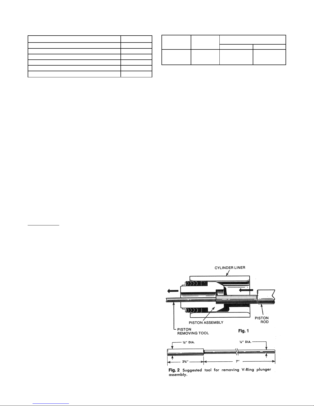
REMOVING PACKiNG
Move assembly to front end of cylinder (top dead center).
Remove valve assembly if required to provide clearance.
Remove cap screw with an Allen wrench. (Allen wrench,
Part No. 8574A11). Retract piston rod and insert tool as
shown. Pull packing assembly out or push by rotating
crankshaft by hand.
5
26850A003
CALL 1-800-577-8111 FOR SALES AND SUPPORT
CAUTION: Also inspect cylinders for linear grooving by
running your thumbnail circumferentially around bore of
cylinder. If any grooving is detected also replace
cylinders. New packing will rapidly cut or wear out in
grooved cylinders.
INSTALLING PACKING
Assemble V-Rings onto stud as shown. Lubricate the
outside of the assembly with Molykote or other grease
for ease in insertion – do not use a graphite type grease.
When installing each V-Ring assembly, rotate crankshaft
until piston rod is at forward position. Place copper
gasket 5030A128 in position in stud using a small
amount of Permatex to hold in place. NOTE: Apply
Loctite RC35 to capscrew prior to piston installation.
Follow instructions on label and make certain threads in
piston rod are clean and free of any grease or oil.
Assemble capscrew, etc., into piston assembly and
push into cylinder. Torque the capscrew to 50 ft. lb. using
a hexagonlal socket attachment 3/8" across flats.
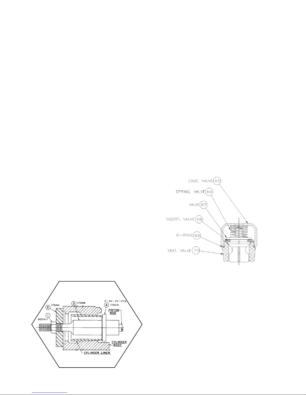
REMOVING CYLINDERS, (Fig. 5)
1. First remove packing as outlined previously.
2. Rotate crankshaft until piston rod is in rear position.
3. Insert puller (3) through inside of cylinder and pilot over
piston rod.
4. Insert disc (4) into slots on puller (3).
5. Slip plate (2) over threads on puller (3) as shown.
6. Screw nut (1) on thread on puller (3) and snug up.
7. Tighten nut (1) until liner breaks loose.
8. Loosen nut (1) and slip disc (4) out of slots.
9. Remove puller (3) and repeat to remove other
cylinders.
Reasonable care and judgment should be used when
installing the new cylinder. Clean out any accumulation
of loose rust or corrosion in cylinder body. Install a new
O-ring in groove on tapered portion of cylinder, lubricate
O-ring with oil or grease for ease in insertion. Position
cylinder carefully by hand to avoid cutting the O-ring.
Drive into position firmly with a wooden block and mallet.
Never use a hydraulic press; excessive force can cause
damage and make cylinders very difficult to remove for
later replacement.
REMOVING SEATS: Wing Guided Valves
A. First remove valve caps, (61) and cylinder
caps, (72) which provide access to suction and
discharge valves. Remove the stainless steel cage
which serves as a valve guide and spring retainer.
Remove cage (65), spring (66), and valve (67), from
the pump fluid end. (Fig. 6)
. Suction valve seats are removed as above except
two stud lengths are joined using coupling
CYLINDER INSTALLATION
1¾”,
Fig. 5
Fig. 6
SUCTION & DISCHARGE VALVE ASSEMBLY
Part No. (TS18-AR0-AC0714)
6
26850A003
 Loading...