

MyEnergy Domain TZ PWS 01 Users manual
MyE Home Energy Management System Manual
1
2
3 4
5
6
7
8
9
10
11 12 13 14 15 16
17
18
19
20
21 25 26
27
28
22 23 24
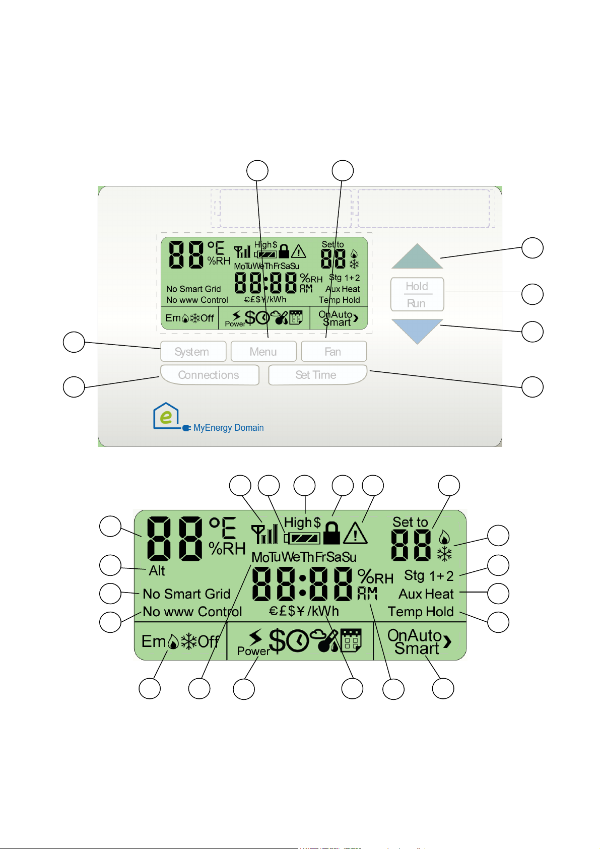
Front view of the thermostat
LCD Display
Button Operations and Related LCD Display
1 – Communications button. it will toggle through the following control options:
• Web server control and smart-grid control
• Web server control and no smart-grid control
• smart-grid control and no Web server control
• No Web server control and no smart-grid control.
If there is no smart-meter detected, then the button will only toggle:
• Web server control
• No Web server control.
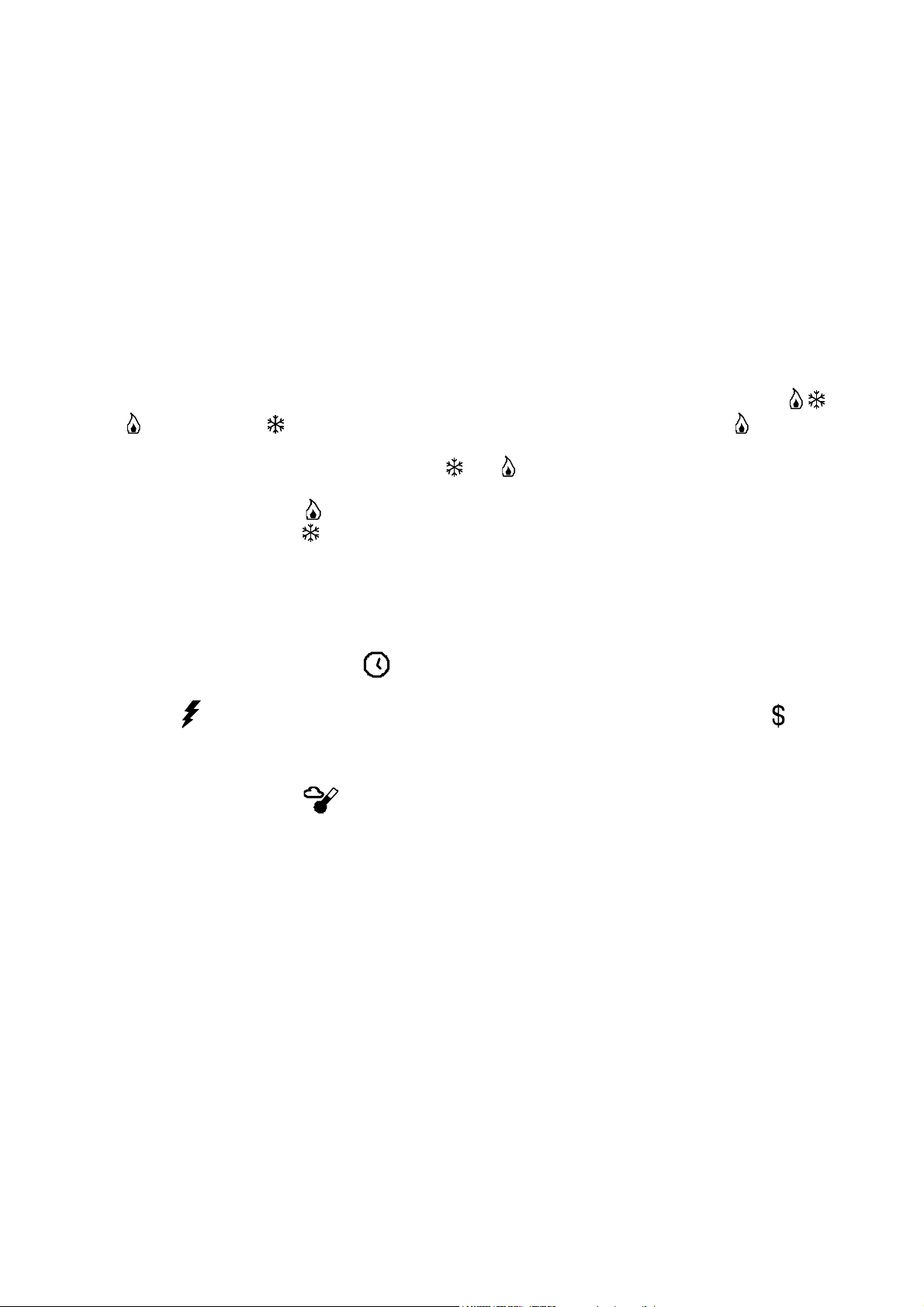
2 – SYSTEM button. Pushing the SYSTEM button will cycle through the system modes auto( ),
heat ( ), Off, and cool ( ). If the system is a heat pump, then emergency heat (EM ) will also
be available, and that comes after “heat” and before “Off”.
• AUTO is represented by having both the and active.
• OFF indicates that the system is turned off.
• A single heating icon ( ) indicates that the system is in heat-only mode.
• A single cooling icon ( ) indicates that the system is in cool-only mode.
• Em indicates that the system is in Emergency Heat mode.
•
CAUTION: To avoid possible compressor damage, do not use Auto Changeover if the outside temperature drops
below 50°F (10°C).
3 – Menu button. Pressing this button will change the content of the time display area and change
the text displayed above the Menu button.
• When the system is reset, Clk will be active and the time will be displayed in the middle
of the LCD.
• Power is the instantaneous power use for the whole building and is in kWh. Cost is the
current cost of electricity per kWh. Power and Cost require that a smart-meter is present,
and smart-grid control is enabled. If there is no smart-meter in the house or there is No
smart-grid control, this choice will be skipped.
• External temperature . If there is no web connection, then outside temperature won’t
be available either.
4 – FAN button.
• This button will toggle between AUTO fan and forcing the fan ON.
5, 7 – Up, Down Buttons. Used to set temperature and set points.
• When in time set mode, the buttons are used to adjust hour, min, am/pm, and day.
• When in the default (temperature) mode, the buttons will set a temporary HOLD that will
affect the current mode (either heat or cool) until the program’s next schedule change.
• Pushing the up button will increase the selected value. The down button will decrease the
selected value.
• When the thermostat is in DR Hold mode, pushing the up/down buttons will not modify the
temperature. If the user wants to override the DR HOLD, then he needs to explicitly click
on the hold/run button.
6 – Hold/Run button. The button is used to HOLD a temperature, or to RUN (resume) the current
program.

• If Hold is “off”, then pressing HOLD/RUN when the thermostat is in its default mode will
implement a set point Hold until you release it.
• If Hold is “on”, then pressing HOLD/RUN will release the hold and return to the default
weekly thermostat program.
8 – SET TIME button. Used to set the time for the Thermostat.
• Press the set_time button to enable set_hours mode. Then Press the up/down buttons to
change the hours.
• Then Press the set_time button again to move on to set minutes mode. Then Press the
up/down buttons to change the minutes.
• Then Press the set_time button again to move on to set AM/PM mode. Then Press the
up/down buttons to toggle between AM and PM.
• Then Press the set_time button again to move on to set day mode. Then Press the
up/down buttons to cycle through the days of the week.
• Then Press the set_time button again to start the set_time mode from the beginning.
• The active field (hours, minutes, etc) will blink while active.
• Press any button other than the up, down buttons while the system is in “set time” mode to
cancel the changes and revert the system to normal operating mode (this will NOT change
the hold/resume status.)
• When the adjustments are done, press the Hold/Run button to exit TIME ADJUST mode.
9 – Temperature/humidity display. This indicates the current temperature (and humidity if an
indoor humidity sensor is connected).
• The units (C or F) are defined by the user using the graphic interface (through the local
server, or the web, or handheld interface).
• If an indoor humidity sensor is connected, the display will alternate between the
temperature and the humidity.
10 – ALT field. This indicates that the temperature sensor used to drive the thermostat is the
alternate sensor, either located in the Mediator or in an external temperature sensor.
• If lit, the temperature in the temperature field (9) will reflect the temperature at the
alternate sensor. Otherwise, the temperature reflects the sensor located at the thermostat.
• The selection of the temperature sensor to use is by default at the Thermostat. A setting in
the web page or mediator is where the user can change to the ALT sensor.
11 – Signal Strength. Status field for connection with the mediator
• Shows the signal strength of the connection with the Mediator, from 0 to 3 bars.
• If the thermostat loses communications with the Mediator, no bar is shown and the antenna
will flash. In this case, all control is local to the thermostat.
12 – BATTERY field. There are three fill levels, corresponding to the strength of the batteries.
When it starts flashing, please replace the batteries soon.
13 – HIGH COST (High $). Indicates a spike in electricity cost
• If the electric utility company indicates that current electricity prices are about to spike or
already high, then this field will flash until the prices come back down below the high cost
level.
• This field is only used if there is some way to receive the information on utility pricing, and
the utility has a variable price program.
• The user can define the high price limit using MyEnergyDomain.com in the thermostat setup
section. For example, it could be defined as anything above $.30/kwh, or 2x the base rate.
 Loading...