

MAXDTC-BTFamilyUserManual
Description
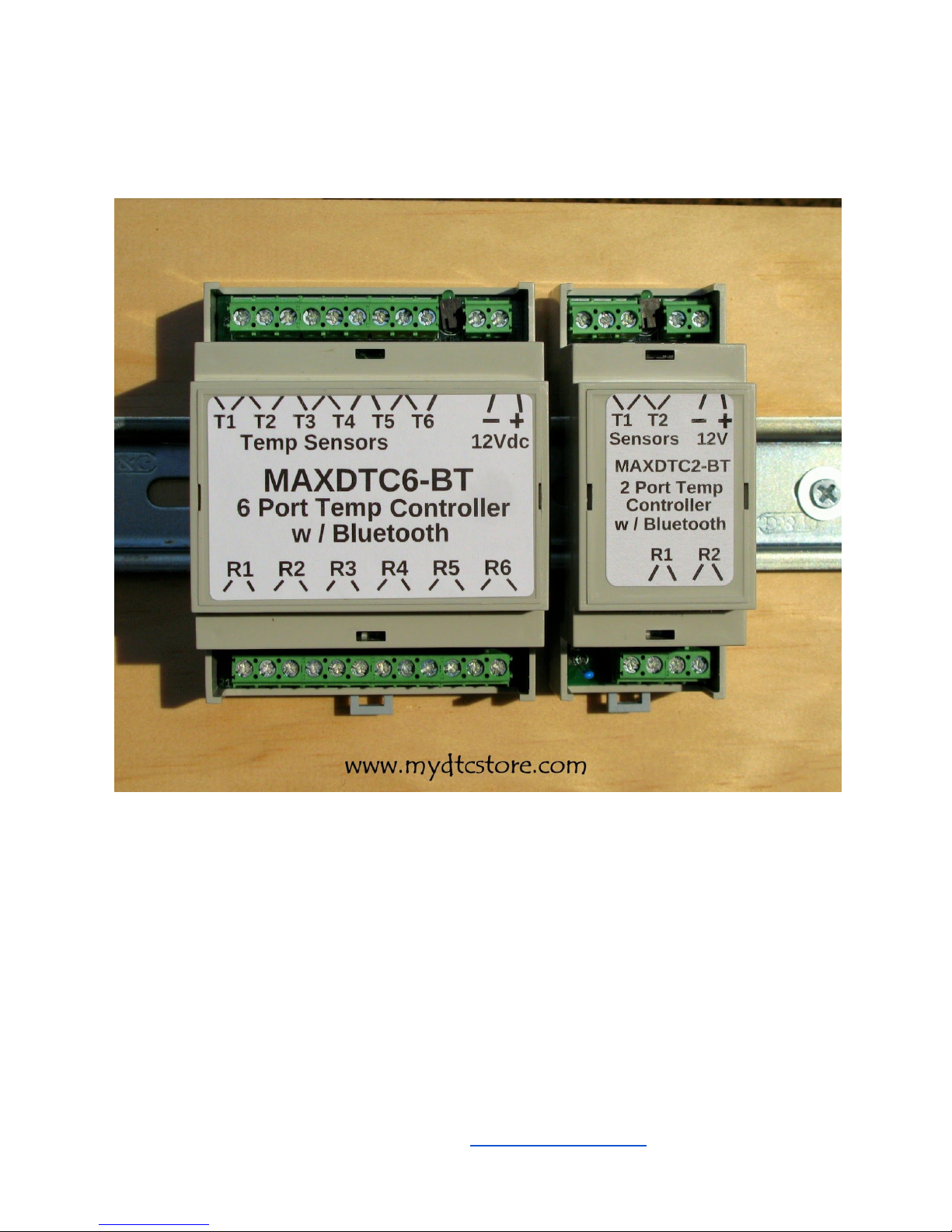
The MAXDTC-BT is a fully programmable industrial temperature controller. The
controller is configurable and monitorable thru a Bluetooth connection from your Android
bluetooth enabled smartphone or tablet. The MAXDTC6-BT can run 6 independent
programmable temperature control rules. The MAXDTC2-BT can run 2 programmable
temperature control rules. All controllers have FLASH memory for saving and restoring
configuration after power loss.
The controllers have either 2 or 6 external temperature sensor inputs (-40F - 300F / -40C
- 150C) and 2 or 6 dry relay contact outputs (120/240VAC @ 3A, 0-30VDC @ 3A) for switching
MAXDTC-BT User Manual - Rev A www.mydtcstore.com 1
both AC and DC loads depending on model. The controllers are din rail mounted and powered
by 12VDC. They have gray ABS enclosures and screw terminal for all connections.
Applications
● Differential Heating and Cooling (Solar hot water heating, root cellar cooling, attic
cooling)
● Industrial Heat and Cool Thermostat/Alarming (-40F - 300F / -40C - 150C setpoints)
● Outdoor Reset Control for Wood Boilers, with programmable one shot restart timer
● Multi Input/Output Industrial Temperature Alarming
● Remote control of all outputs from smart phone with one shot timer capability.
● Greenhouse / hydroponics temperature control and alarming
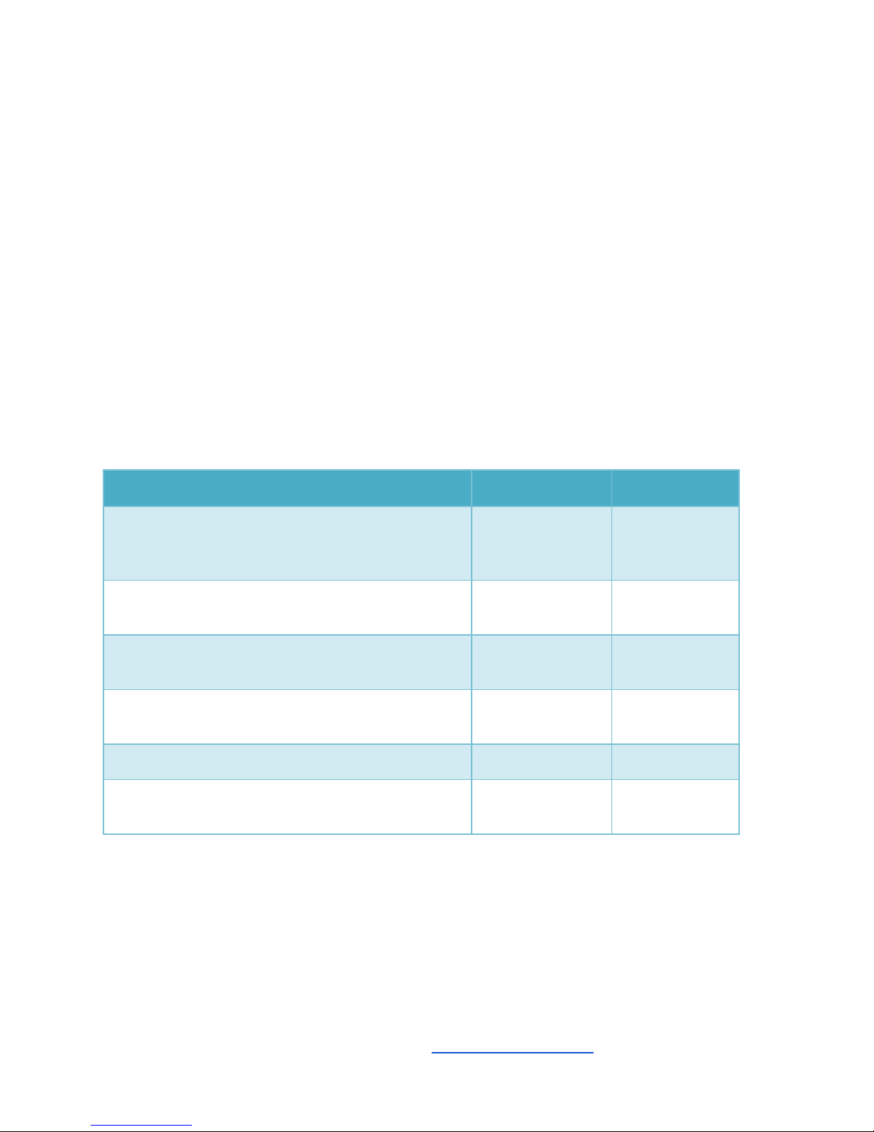
Device Capabilities
Number of Control Rules Supported
MAXDTC2-BT
MAXDTC6-BT
Differential Temperature Control
(Solar Heating or Root Cellar / Attic Cooling)
(2 Inputs / 1 Output)
1
3
Thermostat (Heat or Cool) (-40 - 300F range)
(1 Input / 1 Output)
2
6
Outdoor Reset Control (wood stove boiler)
(2 Inputs / 1 Output)
1
3
Periodic Timer
(0 Inputs / 1 Output)
2
6
Manual On/Off
2
6
Time Controlled One-Shot
Boiler Reset / Remote Control Timed Run
2
6
MAXDTC-BT User Manual - Rev A www.mydtcstore.com 2
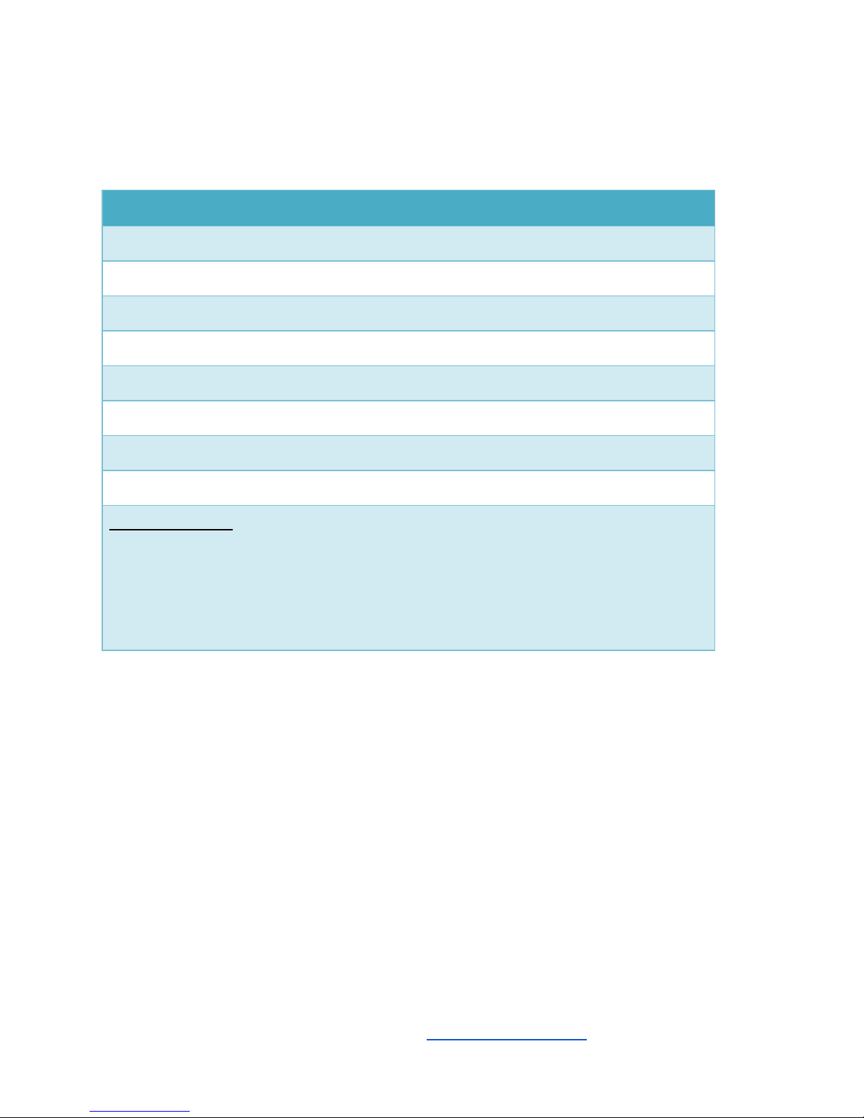
Controller Specifications
Specifications
Relay Outputs: 0-240VAC/ 0-30VDC, 3 amps
Temperature Inputs: -40F - 300F Range, NTC 10K thermistor 1%
Power Input Voltage: 12vdc nominal (10.8V - 14V)
Power Input Current: 40mA + 16.7ma per active relay
Mounting: DIN RAIL
Indicator: Green LED
Communication: Bluetooth 2.0, Range: ~50ft line of site (nominal)
Configuration Memory: Non-Volatile, power fail safe
Enclosure / Size:
MAXDTC2-BT:
ABS/PC Blend, Gray, 1.429" L x 3.551" W (36.30mm x 90.20mm) X 2.264" (57.51mm)
MAXDTC6-BT:
ABS/PC Blend, Gray, 2.795" L x 3.551" W (70.99mm x 90.20mm) X 2.264" (57.51mm)
MAXDTC-BT User Manual - Rev A www.mydtcstore.com 3
Installing a Bluetooth Terminal Program
In order to communication with the MAXDTC-BT controllers, you will need to load a Bluetooth
Terminal program on your android smartphone or tablet. The program is free and can be
downloaded for the Google Play Store.
The program that works best is Bluetooth Terminal HC-05 from mightyIT.
You can search for it and download it from the Google Play Store. Here is a link for it as well:
https://play.google.com/store/apps/details?id=project.
bluetoothterminal&hl=en
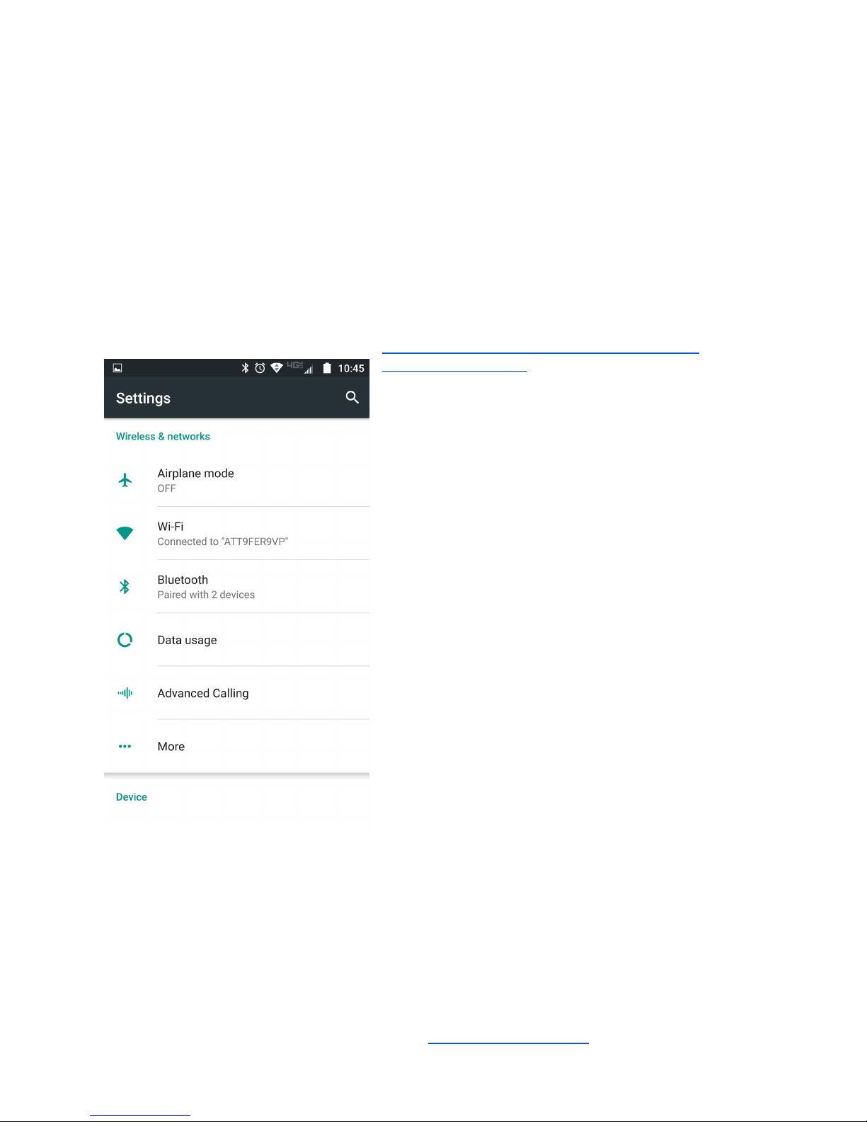
First Connect to Bluetooth
with Android
Before you can connect to the controller via the
Bluetooth Terminal HC-06 program, you need to
connect to the controller via the Bluetooth settings on
your phone. You can navigate to the Bluetooth
settings screen by going to Settings then selecting
Bluetooth. Once here, have the phone or tablet
check for available devices. You will want to have
the controller powered up for a minute before doing
this. When you scan for available devices, you should
be able to find the controllers onboard bluetooth device
which shows up as HC-06 or BT04-A. Once you see
this, go ahead and select it to connect to the device.
Once your phone has found and connected to the
controller in this way, you are ready to connect to the
controller with the Bluetooth Terminal HC-05
application.
MAXDTC-BT User Manual - Rev A www.mydtcstore.com 4
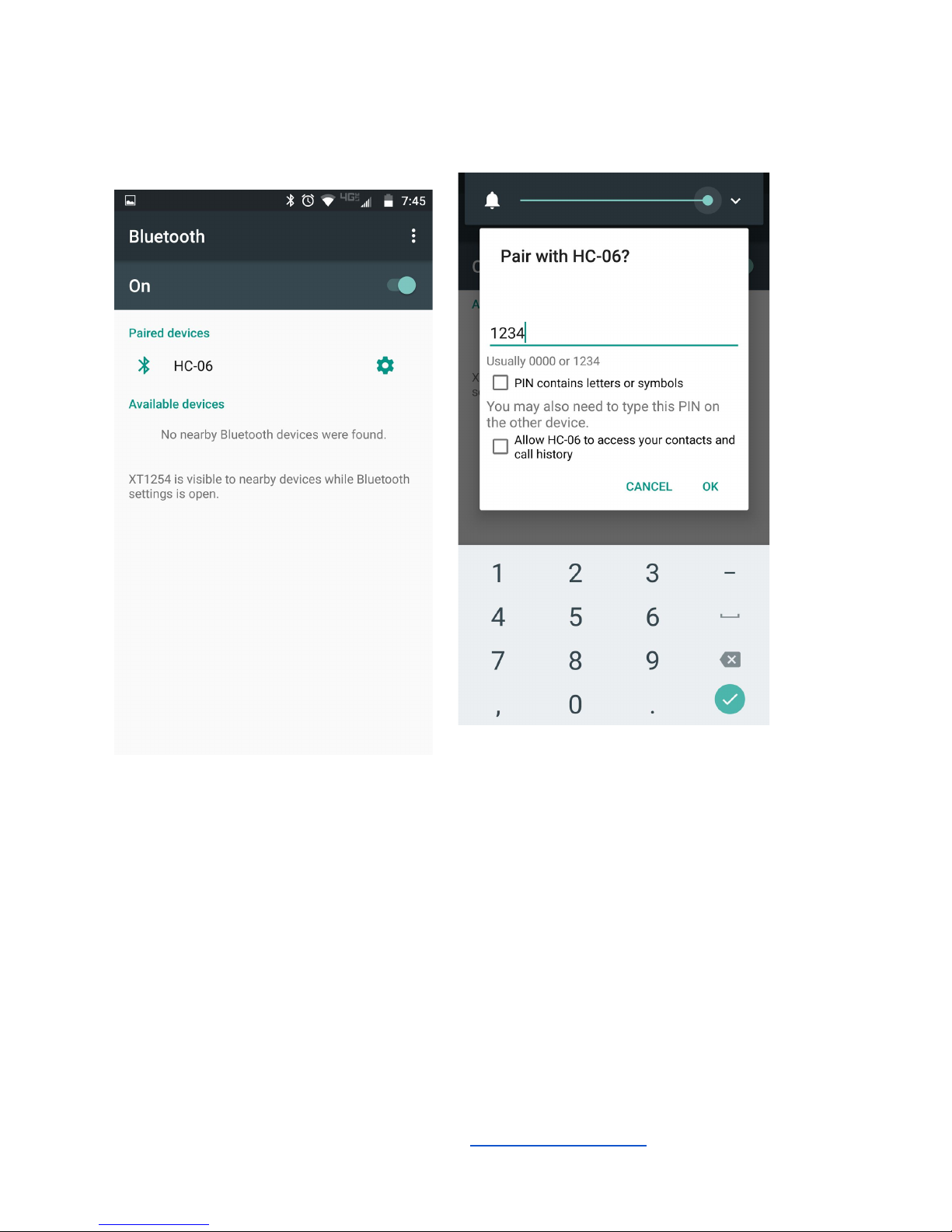
In the bluetooth settings go ahead and pair with the discovered HC-06 device. You will need to
enter a password to do this. The password for the HC-06 and BT04A bluetooth is 1234.
After pairing with the controllers bluetooth, you are ready to connect to it with the terminal
application program.
Assuming you have loaded the serial terminal program, go ahead and run the Bluetooth
Terminal HC-05 application..
MAXDTC-BT User Manual - Rev A www.mydtcstore.com 5
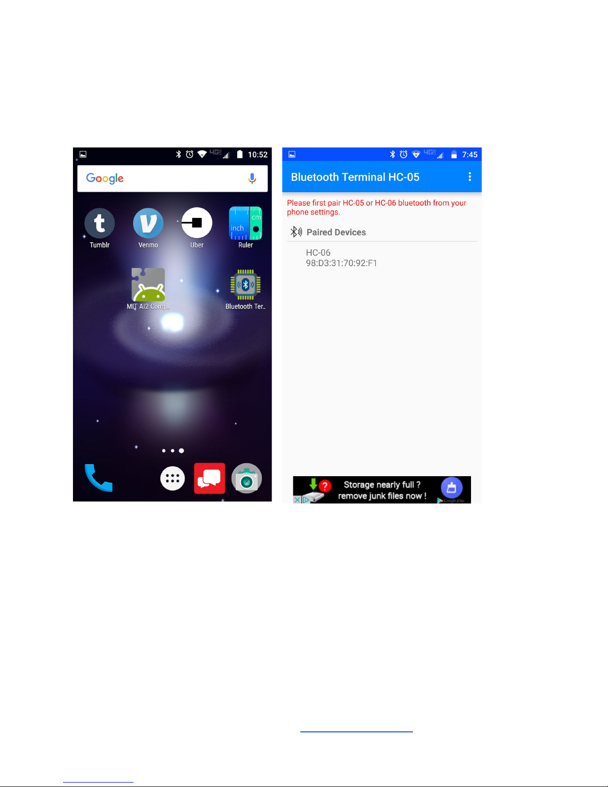
Here is the Bluetooth terminal application on one of the startup screens on the phone. When
you run it you should see a connection choice for HC-06 or BT04-A like below if your have
connected with the phone’s bluetooth settings previously.
After running the app it will show you a list of paired devices. Select the HC-06/BT04-A device.
Once selected, the smartphone will attempt to connect to the controller. It should flash a
connecting / connected message and take you to the terminal screen like shown below.
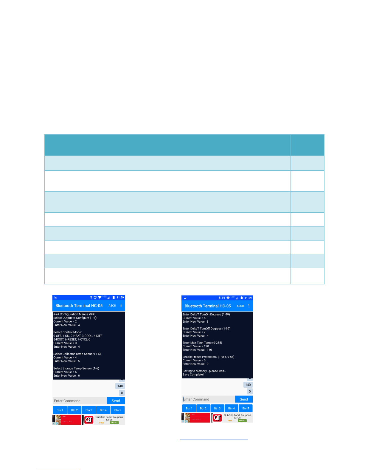
Go ahead and tap the enter command tab and hit an ‘s’ and then the Send button. The
controller should respond with a Status display and the main menu. At this point you can
monitor and configure your controller thru the application.
MAXDTC-BT User Manual - Rev A www.mydtcstore.com 6
Configuring the Controller
Differential Heating and Root Cellar Modes (DIFF / ROOT)
These modes are used for solar hot water and air heating and root cellar or attic cooling. DIFF
mode is used for heating. ROOT mode is used for differential cooling applications like root
cellars..
Configure Differential or Root Cellar Menu Descriptions
Value
Range
Select Output to Configure (1-6):
1-6
Select Control Mode: 0-OFF, 1-ON, 2-HEAT, 3-COOL, 4-DIFF
5-ROOT, 6-RESET, 7-CYCLIC
4-5
Select Collector Temp Sensor (1-6):
(ROOT Mode) Select Outside Temp Sensor (1-6):
1-6
Select Storage Temp Sensor (1-6) or (Root Mode) Select Cellar Temp Sensor (1-6):
1-6
Enter DeltaT TurnOn Degrees (1-99):
1-99
Enter DeltaT TurnOff Degrees (1-99):
1-99
Enter Max Tank Temp (0-255) or (Root Mode) Enter Min Cellar Temp (0-255):
0-255
Enter Freeze Protection? (1-yes, 0-no) or (ROOT Mode: None)
0-1
MAXDTC-BT User Manual - Rev A www.mydtcstore.com 7

Outdoor Reset Mode (RESET)
Outdoor reset mode is used to automatically adjust the setpoint for a wood boiler based on
outdoor temperature. The controller will automatically adjust the setpoint higher when the
outside temperature gets very cold as well as reduce the setpoint when the outdoor temperature
warms up. This reduces wood consumption and enhances comfort.
Reset_setpoint = 70 + ( ( 70 - Outside Temp ) * SLOPE / 10) - Fahrenheit
Reset_setpoint = 21 + ( ( 21 - Outside Temp ) * SLOPE / 10) - Celsius
Here is a link to a spreadsheet for comparing calculated setpoints vs outside temperature and
the slope setting:
https://docs.google.com/spreadsheets/d/1uj_T8KyJOKdhtVgsXukm8cQ8C06riTzFjORUtoDk3Fk
/edit?usp=sharing
Configure Outdoor Reset Menu Descriptions
Value
Range
Select Output to Configure (1-6):
1-6
Select Control Mode: 0-OFF, 1-ON, 2-HEAT, 3-COOL, 4-DIFF
5-ROOT, 6-RESET, 7-CYCLIC
7
Select Outside Ambient Temp Sensor (1-6):
1-6
Select Boiler Temp Sensor (1-6):
1-6
Enter Slope Value (x10) (1-99):
1-99
Enter Reset Hysteresis (1-99):
1-99
Enter Maximum Boiler Temp (0-255):
0-255
Enter Minimum Boiler Temp (0-255):
0-255
MAXDTC-BT User Manual - Rev A www.mydtcstore.com 8

Thermostat Heat and Cool Modes (HEAT / COOL)
Configure COOL / HEAT Thermostat Menu Descriptions
Value Range
Select Output to Configure (1-6):
1-6
Select Control Mode: 0-OFF, 1-ON, 2-HEAT, 3-COOL, 4-DIFF
5-ROOT, 6-RESET, 7-CYCLIC
2 or 3
Select Thermostat Temp Sensor (1-6):
1-6
Select Setpoint Temperature (-40-300F):
-40 - 300
Enter Hysteresis / Dwell Degrees (1-99):
1-99
Use HEAT or COOL mode to provide thermostat
heating or cooling or provide temperature alarming
for motors or refrigeration.
Setpoints from -40F to 300F (or celsius equivalent)
are supported by the controller.
Programmable Hysteresis and Dwell temperature
from (0 - 99F) (or celsius equivalent) is also
provided to adjust the run time and depth of
temperature cycling required.
The inputs sensor selection for these modes will
allow multiple thermostats to be controlled by the
same temperature input if desired for controlling
multiple output devices from one sensor.
The controller will print Saving to Memory when
the settings are committed to memory.
MAXDTC-BT User Manual - Rev A www.mydtcstore.com 9

Cyclic Timer Mode (CYCLIC)
Configure Cyclic Timer Menu Descriptions
Value
Range
Select Output to Configure (1-6):
1-6
Select Control Mode: 0-OFF, 1-ON, 2-HEAT, 3-COOL,
4-DIFF
5-ROOT, 6-RESET, 7-CYCLIC
7
Enter Cyclic On Time (1-32000):
1-32000
Enter Cyclic Off Time (1-32000):
1-32000
Cyclic Timer is used for things like hot water
recirculation pumps, misting systems, buffer tanks.
Configure the On time in seconds followed by the off
time in seconds. The controller will turn the output
on for the on time setting, then off for the off time
setting then repeat.
The controller will print Saving to Memory when
the settings are committed to memory.
MAXDTC-BT User Manual - Rev A www.mydtcstore.com 10

Changing the Controller Preferences
Preferences Menu Descriptions
Value Range
Enter Temperature Units (0-Fahrenheit, 1-Celsius):
0-1
Enter One Shot Time Seconds (1-32000)
1-32000
In preferences you can change the temperature
units that the controller uses to display the
temperature sensors. It will not automatically
change the parameters you have entered when
changing units. You will have to change those
setting manually.
The settings will not be saved to nonvolatile
memory until you have changed all the settings in
the menu group (Temperature Units, One Shot
Time Seconds).
The controller will print Saving to Memory when
the settings are committed to memory.
This configuration screen is activated by entering a
‘p’ character.
MAXDTC-BT User Manual - Rev A www.mydtcstore.com 11

Status and Monitoring the Controller
Info Screen
The Info screen provides the SW revision of the
controller, Total Runtime in hours and days,
Runtime since last reset, currently selected
temperature units and one shot timer
seconds configured.
This screen is activated by entering a ‘i’
character.
MAXDTC-BT User Manual - Rev A www.mydtcstore.com 12

Rules Screen
The rules screen shows a snapshot of all the relay control rules you have entered and their
parameter values. It is accessed by entering an ‘r’ at anytime.
The rules screen shows the mode, temperature
inputs selected, setpoints and parameters for
each relay control rule configured. For outdoor
reset it also shows the calculated reset setpoint
temperature.
MAXDTC-BT User Manual - Rev A www.mydtcstore.com 13

Status Screen
The status screen shows a snapshot of all the relay control inputs temperatures and output
state for each relay. It is accessed by entering an ‘s’ at anytime. It shows the controlling
variables and any overtemp / under-temp status states. As an example below the R1: Root
Cellar Mode, Outside and Cellar temps (O/C) are shown, the calculated deltaT, and output relay
is OFF.
Across the top it shows current temperature
readings of all inputs. From there is shows the
relay control rules configured mode, controlling
input values, and relay output state at the end.
If an under or over temp state is overriding the
control rule it will show which one. On R6 a reset
control rule is setup and MINT value indicates
that the minimum temperature is being violating
and forcing the output on. The RSP value is the
reset setpoint calculated and being used based
on the ambient temperature and slope you have
selected. This value is bounded by the Min
Temperature and Max temperatures you
configured for the rule.
You will see a trigger one shot status with
amount of time left if you do a one shot trigger on
any of the outputs in this display as well.
MAXDTC-BT User Manual - Rev A www.mydtcstore.com 14

History Screen
The history screen displays the high and low temps read on the inputs since the last history
reset. They are displayed in the units you have selected in the preferences. It is accessed by
entering an ‘h’ at anytime. Hitting a ‘1’ at the prompt resets the high and low readings to current
readings.
Power LED
The green LED should like and blink once a second when the controller is operating properly. If
the LED is not lit, check the power inputs and verify you are providing +12VDC and Ground to
the power inputs located next to the LED. Verify polarity is correct.
When power is first applied, it can take approximately 6 seconds to initialize.
Installation and Wiring Info
Temperature Sensor Inputs and Wiring
The temperature sensors sold with the controller are matched in characteristic to the controller
and will provide the most accurate readings. Using other 10K NTC thermistors is not
recommended. There are water-proof versions of the temp sensor available as well.
Temperature sensors may be extended 50 ft with twisted pair telephone cable or CAT5 cable
without dramatically affected the reading accuracy. Do not include power wiring in the bundle to
other devices as it may put noise on the temperature reading. Always separate measurement
sensor wiring from power / load device power wiring where possible.
The sensor inputs are wired with a common terminal between each two inputs. This common
wire should have one wire from each temp sensor input adjacent to it.
MAXDTC-BT User Manual - Rev A www.mydtcstore.com 15

Temperature Sensors for MAXDTC-BT Controller
There are two types of temperature sensors available for use with the MAXDTC-BT. The
Standard Temp sensor and a waterproof temp sensor are both available from the website.
These sensors are matched to the controller and will provide the most accurate readings.
Each controller comes with two standard temp sensors.
Additional sensors are available for purchase off the wesite: www.mydtcstore.com
MAXDTC-BT User Manual - Rev A www.mydtcstore.com 16

Power Input (12VDC)
The power input to the controller requires 12VDC input, which is on the top right side of the
controllers. It is recommended to use a DIN rail type 12vdc power supply with a well regulated
output for the best performance and reliability of the controller. These are available off the
website, but do not come standard with the controllers.
If you need to run large DC pump, you will need to have a higher current capacity power supply
(3-5 Amp recommended). These supplies have an adjustable output voltage trimmer as well.
MAXDTC-BT User Manual - Rev A www.mydtcstore.com 17

Controller Output Relay Wiring to Load Devices
Wiring load devices to the controller relay outputs is simple. Connect the Hot or Positive power
source wire to one side of a relay output, connect the other side of the relay output to the Hot or
Positive power input of the load device. The controller will switch the power to the load device
by closing the relay.
It’s always a good idea to put a fuse on the output of the controller to the input of the load
device.
MAXDTC-BT User Manual - Rev A www.mydtcstore.com 18

Controller Temperature Sensor Wiring
The temp sensors are wired to T1-T6 sensor inputs (T1-T2 on smaller MAXDTC2-BT version).
Each group of two temperature sensor inputs shares a common ground terminal that both
temperature sensors share in common. See diagram.
The temperature sensors can be extended 50ft with twisted pair telephone wire or equivalent
CAT5 type cable with no appreciable reading error. Avoid running temperature sensor wires
near AC or power connections to load devices which can create noise on the temperature
sensor input.
MAXDTC-BT User Manual - Rev A www.mydtcstore.com 19

External DIN Rail Relay Info
If you need to switch larger power loads than the 5amp onboard relays can handle, consider
purchasing an external DIN rail mountable relay and control it with the onboard controller relay.
Just switch 12VDC power to the external relay coil to support upto 10A load devices.
MAXDTC-BT User Manual - Rev A www.mydtcstore.com 20

Ordering Information and Pre-configuration Options
MAXDTC-BT Controllers can be ordered off the www.mydtcstore.com website. More
information and accessory equipment such as additional temperature sensors, waterproof
sensors, fuses, DIN rail power supplies, terminal blocks, additional DIN rail, and external high
current relays are available for purchase on the website.
If you would like the controller preconfigured to your application before shipment, please contact
us for details.
For OEM inquiries, contact Brian Smith at this email address: smith100griggs@gmail.com .
Have Technical Questions? Send us an email!
Have a question on how the controller works? Send me an email and I will try to answer your
question: Brian Smith - smith100griggss@gmail.com
MAXDTC-BT User Manual - Rev A www.mydtcstore.com 21
 Loading...