

Innovative Solutions
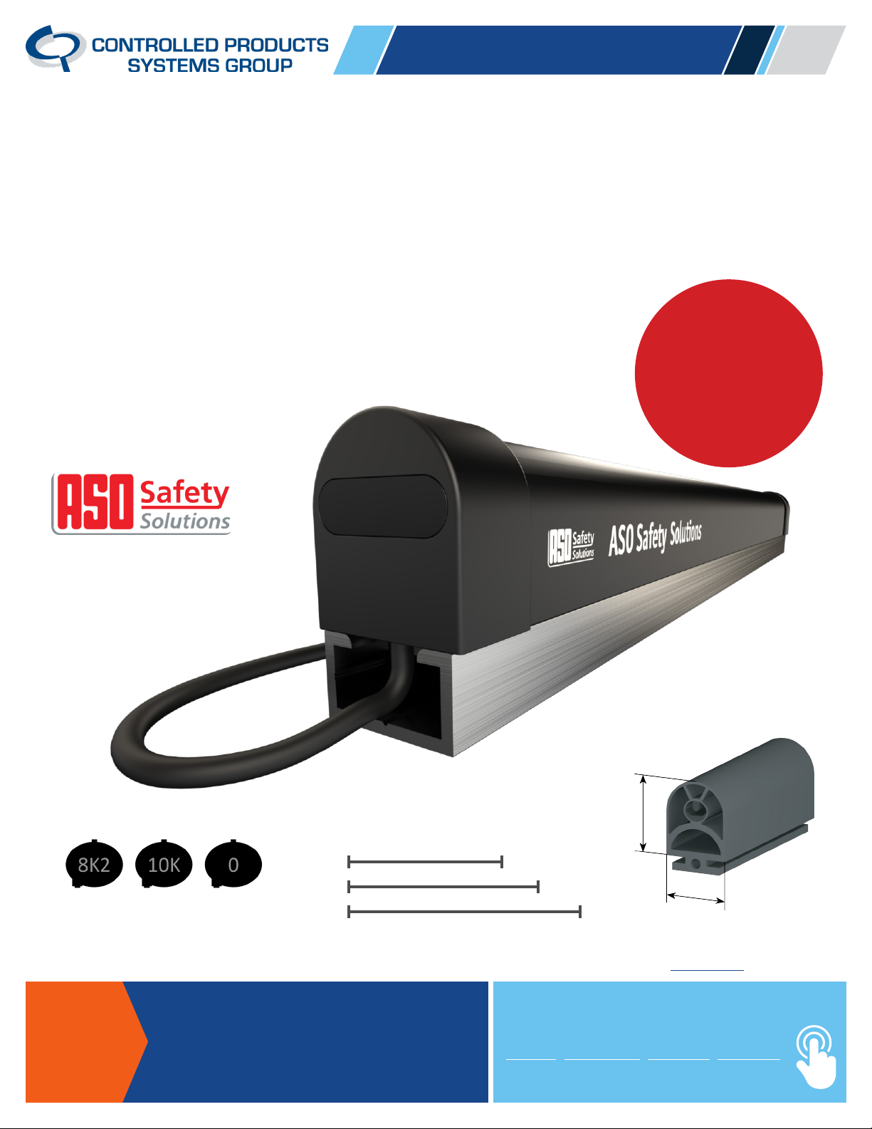
SENTIR KS4 UNIVERSAL EDGE
The KS4 Universal Edge comes with 8.2K, 10K and Normally Open
(non-monitored) termination resistors to enable it to work with a
variety of equipment to meet UL325 standards, plus all legacy
non-monitored applications.
An
The One Edge Solution!
Kit includes: contact edge,
aluminum channel, and all
components to assemble a
complete edge.
Industry
First!
Included Termination Plugs
8.2K 10K
Normally Open
(non-monitored installs)
Available at a CPSG branch near you or buy online.
ASK
The Access
Experts!
National Sales 877-531-6122
Technical Support 877-531-6123
ControlledProducts.com
Available Lengths
4ft
1.2”
5ft
6ft
Stay connected at MyCPSG.com
EVENTS PRODUCTS SUPPORT CAREERS
1”
Assembly Instructions
The KS4 Universal Edge comes with 8.2K, 10K and Normally Open (non-monitored) termination
resistors to enable it to work with a variety of equipment to meet UL325 standards, plus all legacy
non-monitored applications.
This edge is easily assembled and comes in pre-cut lengths of 4ft, 5ft and 6ft.
Safety contact edges may only be assembled and installed by authorized personnel!
ASO GmbH excludes all liability for damage caused of an incorrect assembly and installation of the contact edges!
Click to watch the assembly instruction video or scan the QR code.
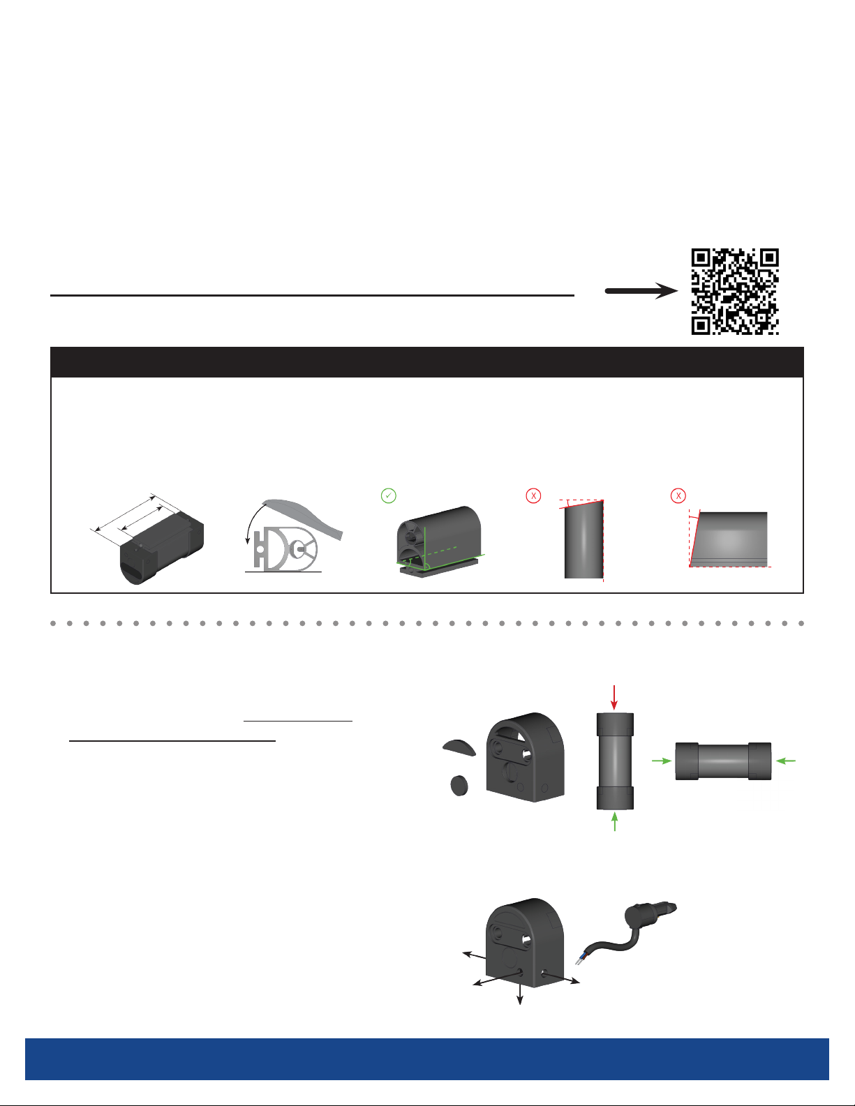
THIS STEP IS ONLY NECESSARY IF TRIMMING IS REQUIRED
Cutting the safety-contact-edge
The safety-contact-edge is cut 1 inch shorter than the nal length dimension to allow for the length of the end caps
on each end. The aluminum channel should be cut to the nal length dimension. Make sure that the cut surfaces are
rectangular and clean, so the cut should be made starting at the chamber side of the safety edge. The scissors or
table lever blade offered by ASO should be used for this purpose.
(L)ength
L - 1”
1) Preparing end caps
A) Water drain plugs - It is necessary
to remove water drain plugs. For vertical
mounting, remove the two marked areas
in the lower end cap, for horizontal
mounting, remove the two marked areas
in both end caps.
B) Connection cable - Choose desired
cable exit of end cap. If necessary, stitch
through the marks.
DO NOT remove drain plugs from
!
the top of a vertically mounted edge.
MyCPSG.com
2

Assembly Instructions
2) Insert lock cap
Press the clamp straight into the hollow chambers around the
internal switching chamber until it is tightly against the surface
of the prole. Then check whether the outer wall of the switching
chamber abuts the clamp. Slight rotational movements of the clamp
can cause misalignment.
3) Insert the contact plugs
(Wired plug at one end and termination plug at the other.)
Choose the termination plug that ts your application
(8.2K, 10K, or NO). For the required sealing, press
both the termination plug and wired plug straight
and rmly into the switching chambers on each end.
The stop point on the plug should be as close as
possible to the end face of the clamp. Then press
the plug a second time to ensure a proper t.
4) Put on end caps
Push the end cap onto the safety edge and x
it with the clip until it rests in the predetermined
position of the end cap and noticeably locks in the
clamp. Then press the xation clip a second time.
Termination Plugs
8.2K 10K
Normally Open
(non-monitored
installs)
5) Electrical testing of the safety contact edge
Measure the contact edge with a multimeter. In
rest position, the resistance value has to be 8.2kΩ,
or 10kΩ ± 500 Ω. When edge is activated, the
resistance should not exceed 500 Ω.
MyCPSG.com
3
 Loading...