

mycom V- Handling Manual

V SERIES
REFRIGERATION DIVISION
SCREW COMPRESSOR HANDLING MANUAL
New V-Series
Screw Refrigeration Compressor
Handling Manual
Supersedes all previous version. This information is for reference use only and subject to change without notice
Revision 2 (June 05,2000) Page 1 of 61

V SERIES
REFRIGERATION DIVISION
SCREW COMPRESSOR HANDLING MANUAL
1. General Description of Mycom V-Series Compressor
Introduction
1.1 Refrigerant Compression Mechanism
1.2 Explanation of Vi (Internal Volumetric Ration)
1.3 Reasons for Adjusting Vi
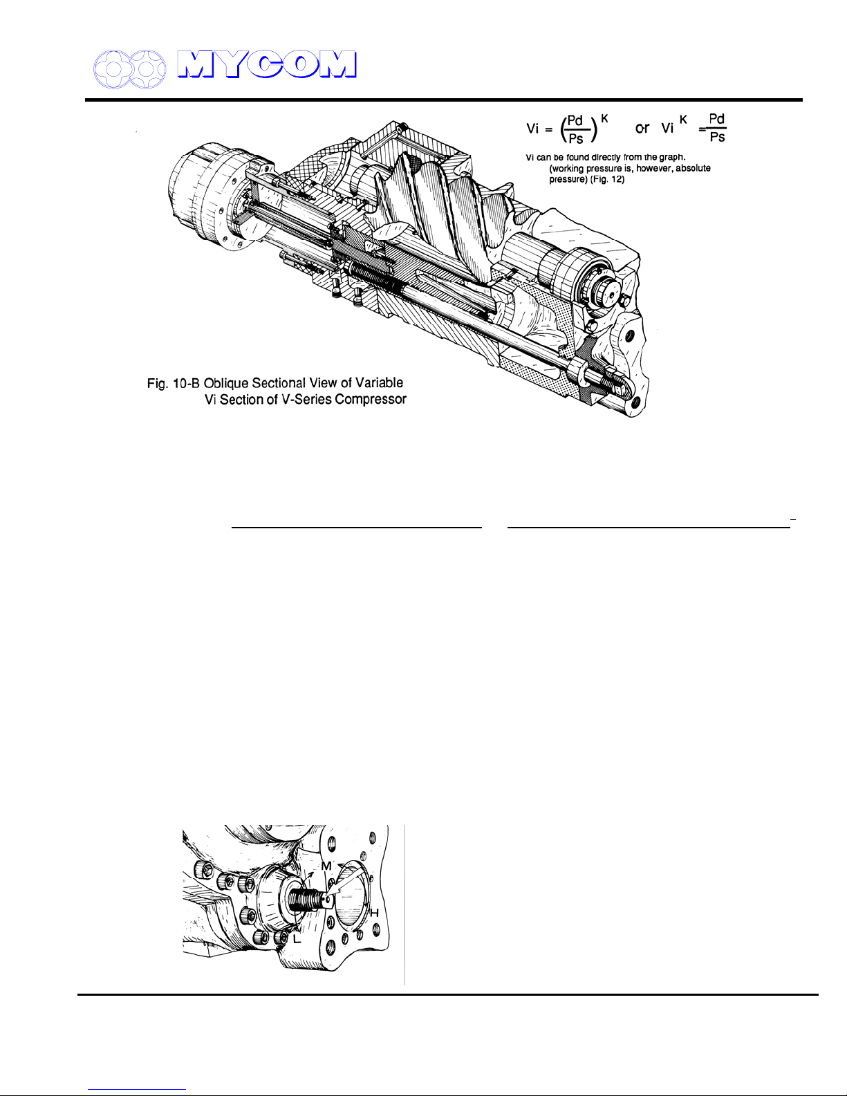
1.4 Variable Vi Mechanism
1.5 External Adjustment of Vi
1.6 Other Component Mechanisms
2. Exploded View of V-Series Screw Compressor
2.1 Parts List
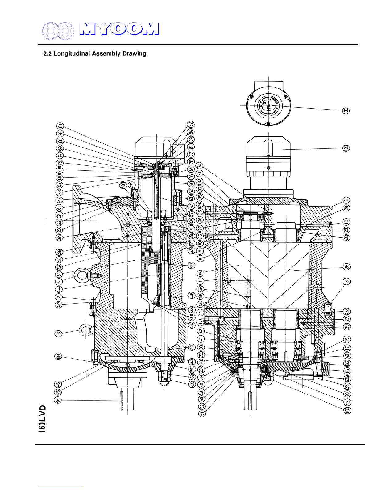
2.2 Longitudinal Assembly Drawing
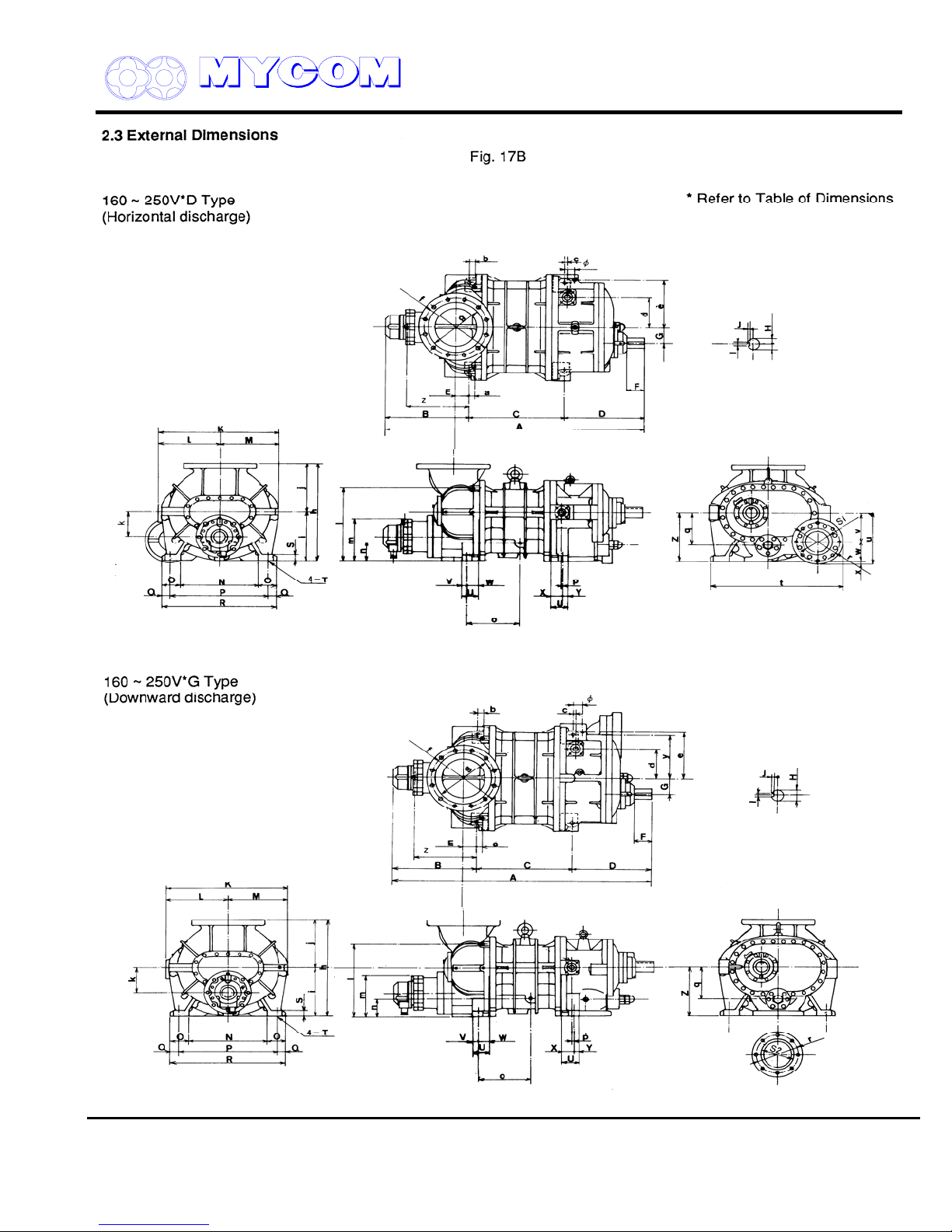
2.3 External Dimensions
3. Disassembly of V-Series
3.1 Preparations for Disassembly
3.2 Hand Tool Kit
3.3 Removing Compressor
3.4 Disassembly Sequence
3.4.1 Mechanical Seal
3.4.2 Unloader Indicator
3.4.3 Unloader Cover
3.4.4 Unloader Piston and Unloader Cylinder
3.4.5 Blind Cover
3.4.6 Balance Piston and Balance Piston Sleeve Portion
3.4.7 Bearing Cover
3.4.8 Thrust Bearing
3.4.9 Suction Cover and Side Bearing
3.4.10 Rotor, Rotor Casing and Variable Vi Slide Valve
3.4.11 Bearing Head and Main Bearing
4. Reassembly
4.1 Bearing Head and Main Bearing
4.2 Rotor Casing, Unloader Slide Bearing, Variable Vi Slide Valve and Bearing Head
4.3 Rotor Casing and Rotors
4.4 Suction Cover
4.5 Thrust Bearing
4.6 Bearing Cover
4.7 Blind Cover, Unloader Cylinder and Unloader Piston
4.8 Unloader Cover
4.9 Mechanical Shaft Seal
5. Disassembly and Adjustment of Unloader Indicator
5.1 Disassembly of Unloader Indicator
5.2 Inspection
5.3 Assembly and Adjustment
6. Standards of Components
Supersedes all previous version. This information is for reference use only and subject to change without notice
Revision 2 (June 05,2000) Page 2 of 61
V SERIES
REFRIGERATION DIVISION
SCREW COMPRESSOR HANDLING MANUAL
1. General Description of MYCOM V-Series Screw Compressor
Introduction
The MYCOM V-Series Screw Compressor (referred to hereafter as the “V Series”) incorporates
numerous improvements. A variable Vi mechanism allows these compressors to be adjusted readily
for most operating conditions and a new tooth profile (0 profile) has been introduced to further
improve performance.
The basic construction of the V Series is the same as standard MYCOM compressors except for the
addition of the variable Vi mechanism.
The operator should have a thorough knowledge of the compressor and the system it is incorporated
into before attempting to disassemble the unit for inspection. Read this instruction manual carefully
before undertaking any work on the system.
This screw compressor is classified as a positive displacement rotary type. It compresses the
refrigerant gas continuously using the volume change between two rotating screw profile rotors.
Refrigerant gas is trapped in the clearance between the two mated rotors and pressure increased by
decreasing the volume. The refrigerant is then discharged as a high-pressure gas
Supersedes all previous version. This information is for reference use only and subject to change without notice
Revision 2 (June 05,2000) Page 3 of 61
V SERIES
REFRIGERATION DIVISION
1.1 Refrigerant Compression Mechanism
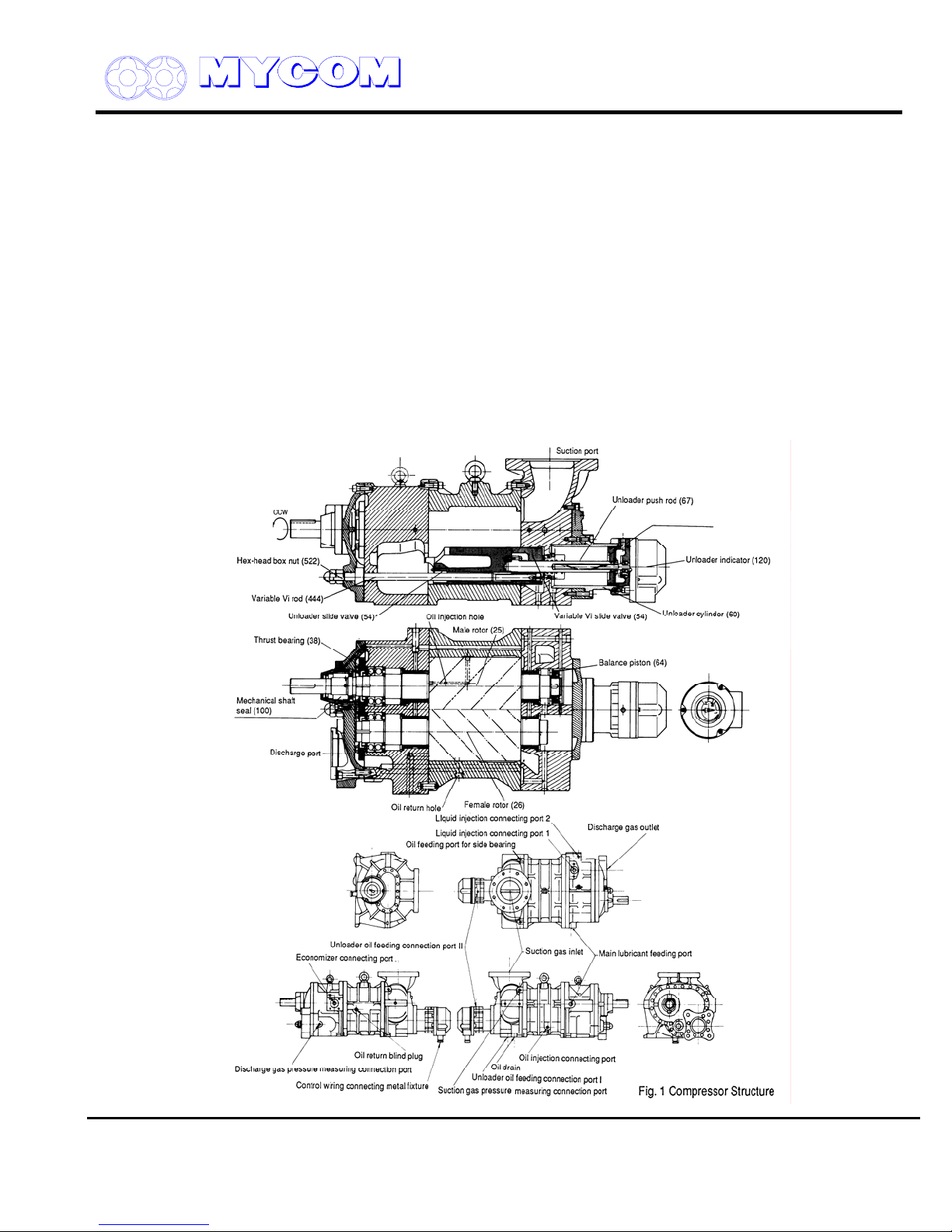
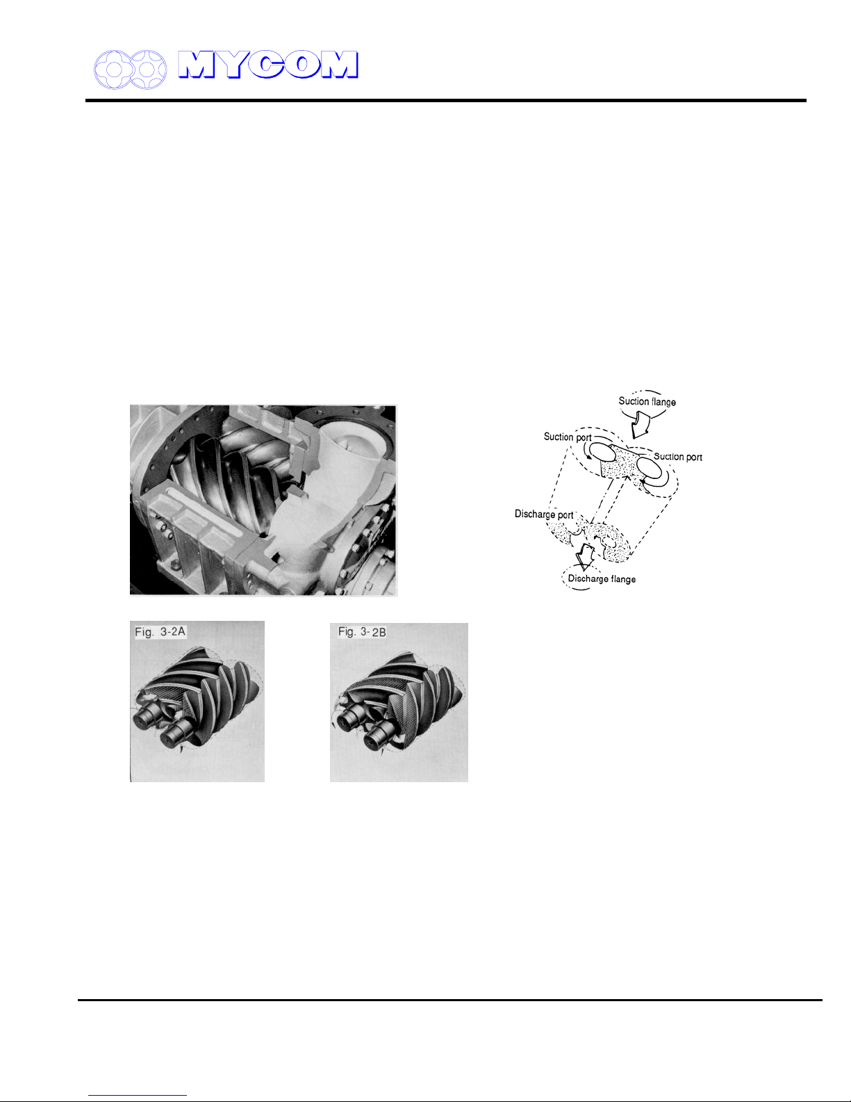
As shown in Figs. 1 and 2, a pair of mated helical gears, or rotors, are mounted in the compressor
casing. The rotor having the four-lobe section is called the male (M) rotor while the one with the sixlobe section is called the female (F) rotor.
A two-pole motor connected directly to the M rotor drives the compressor at speeds of 2,950 rpm or
3,550 rpm (50 Hz or 60 Hz)
Compressor efficiency is directly related to the shape of the rotor lobes. In the case of the V-Series,
the rotors have unsymmetrical profiles in contrast to conventional screw compressor rotor lobes. This
unsymmetrical design reduces the triangular blow off hole between the casing and the rotors to 60%,
minimizing leakage due to the pressure difference.
Normally, an oil film seals the clearance between the leading edges of the rotor lobes and the casing.
With the V-Series, however, a change has been incorporated to raise the pressure of the oil film and
the clearance between the casing and the lobe leading edges is wedge shaped.
SCREW COMPRESSOR HANDLING MANUAL
Fig. 2 Screw Compressor cross sectional view Fig. 3 Rotor Rotation & the Compression Cycle
Supersedes all previous version. This information is for reference use only and subject to change without notice
Revision 2 (June 05,2000) Page 4 of 61
V SERIES
REFRIGERATION DIVISION
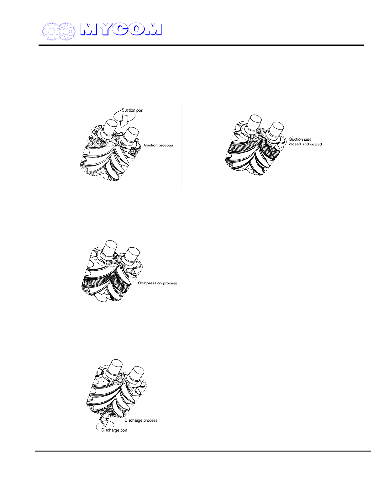
1.1.1 Suction Phase (refer to Figs. 4 and 5)
As shown in Fig. 4, the rotors of different lobe shape mate and the clearance between the M and F
rotors and the casing expands gradually from the suction side as the rotors rotate.
When the clearance reaches maximum as the rotors rotate further, it is sealed by the walls at both
ends of the rotor and becomes independent.
Fig. 4 Suction Phase Fig. 5 Suction Side Sealing
1.1.2 Compression Phase (refer to Fig. 6)
As the rotors further rotate, the suction side of the clearance is sealed by the mating of the lobes and
the volume between the lobes decreases while the sealing line moves toward the discharge side.
SCREW COMPRESSOR HANDLING MANUAL
Fig. 6 Compression Phase
1.1.3 Discharge Phase (refer to Fig. 7)
When the volume is decreased to the designated Vi, the clearance between the discharge port and
the rotors is linked and the refrigerant is pushed to the discharge side.
Fig. 7 Discharge Phase
Supersedes all previous version. This information is for reference use only and subject to change without notice
Revision 2 (June 05,2000) Page 5 of 61

V SERIES
REFRIGERATION DIVISION
SCREW COMPRESSOR HANDLING MANUAL
1.2 Explanation of Vi (Internal Volumetric Ratio)
In the case of a reciprocating compressor, the volume of the refrigerant sucked into the cylinder
decreases and the refrigerant pressure increases as the piston ascends. When the pressure exceeds
the discharge side pressure plus the force of the spring on the discharge plate valve, the refrigerant in
the cylinder pushes open the valve and passes to the discharge side.
In the case of the screw compressor, a volume of refrigerant is sucked into the groove between the
rotors and the volume decreases while pressure increases as the rotors rotate. The process up to this
point is the same as for a reciprocating compressor. When the volume is decreased to the designed
Vi, the groove is linked to the discharge port and the refrigerant is pushed out. The groove is linked to
the discharge port according to the volume of the groove and is not dependent on internal pressure.
Vi (internal volumetric ratio) is used to represent the value of the decreased volume of suction
refrigerant when the groove aligns with the discharge port (or is discharged).
This can be expressed as follows:
Vi =
Volume of suction refrigerant when compression begins
Volume of same quantity of refrigerant at discharge port
In other words, Vi is the ratio of the groove volume after competition of suction to the volume when the
discharge port opens.
Conventional screw compressors have three fixed Vi values, that is 2.63, 3.65 and 5.80, termed “L
port,” “M port” and “H port,” respectively.
The relationships are:
Vi = (P
d/Ps
1/k
)
or Vik = Pd/P
Consequently, the Vi corresponding to the compression ratio changes according to the refrigerant
used.
For approximate values, refer to the graph given in Fig. 12. The new V-Series, Maximizer Series
Screw Compressors, are designed so that the Vi can be adjusted on site according to operating
conditions.
1.3 Reasons for Adjusting Vi
Operating conditions of refrigeration systems are not always constant. As well, the same model of
compressor may be operated under a variety of pressure conditions, e.g., air conditioning, cold
storage and freezing applications. In the case of air conditioning and cold storage, the conditions will
vary depending on the need for cooling, heating, low and high temperature.
Needless to say, compressors must be operated at maximum efficiency under various conditions. The
drawback of the conventional compressor is that a fixed Vi is established for the compressor during
production. This Vi can later be changed by machining the compressor but is limited to change from a
higher to a lower value only. Variable Vi screw compressors in the Maximizer Series were developed
as an answer to this drawback. Many compressors of this type are used in special reefer carrier
applications, but because of the sophisticated structure and relatively high cost, they have not been
popular for general applications.
The V-Series, which incorporates a variable Vi, has consequently been developed for these general
applications.
s
The Vi of the V-Series can be readily changed between L, M and H at the installation plant according
to operating conditions.
Supersedes all previous version. This information is for reference use only and subject to change without notice
Revision 2 (June 05,2000) Page 6 of 61

V SERIES
REFRIGERATION DIVISION
SCREW COMPRESSOR HANDLING MANUAL
With the fixed Vi of a conventional compressor, maximum efficiency can only be obtained when the
system is operating at a pressure equivalent to the designed Vi. Unnecessary power is consumed,
however, when pressure conditions diverge from the designed value. For example, if low compression
ratio (high compression pressure or low discharge pressure) operation is carried out using a
conventional M port compressor (designed for a medium compression ratio), compression will exceed
discharge pressure and power will be wasted.
Fig. 8 Internal Volume Ratio Fig. 9 Relationship between design and
operating conditions
Conversely, if the same M port compressor is used under high compression conditions (high suction
pressure or high discharge pressure), the discharge port opens before internal pressure has
increased sufficiently, allowing refrigerant to flow back from the discharge port. Power is also wasted.
Obviously, if a compressor is to be operated for an extended period under varying conditions, a
variable Vi design is preferable to a fixed Vi type. For a conventional compressor with a high Vi, the
discharge port can be machined to lower the Vi but a unit with a low Vi cannot be changed to a high
Vi type. If a higher Vi is needed, the compressor must be replaced with a new one.
1.4 Variable Vi Mechanism
The Vi of a conventional screw compressor is determined by the combination of the axial discharge
port of the rotors on the bearing head and the radial discharge port of the shaft (radial discharge port
on the unloader slide valve). In the case of a conventional model, the axial and radial elements are
combined to exhibit particular characteristics at partial load. In the case of V-Series compressors, the
Vi can be changed by altering the size of the radial port while maintaining the axial port at Vi 5.10.
Supersedes all previous version. This information is for reference use only and subject to change without notice
Revision 2 (June 05,2000) Page 7 of 61
V SERIES
REFRIGERATION DIVISION
SCREW COMPRESSOR HANDLING MANUAL
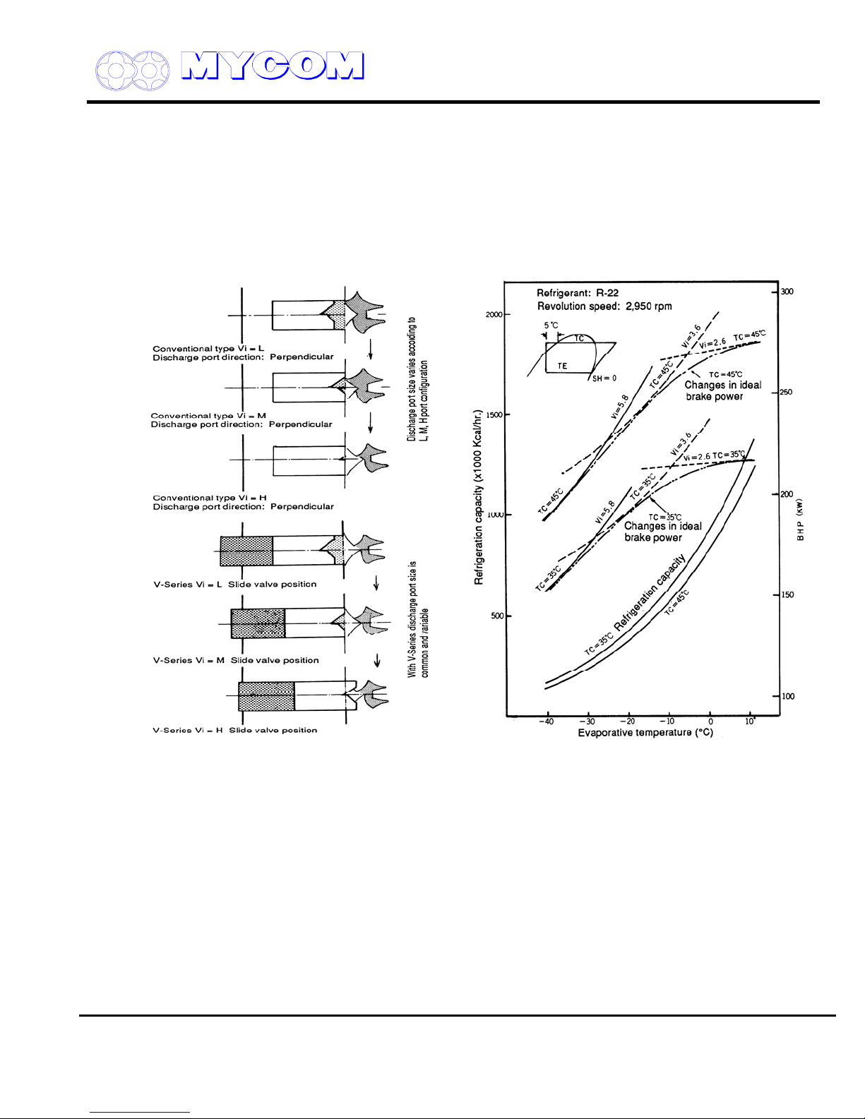
As shown in Fig. 10A, the radial port of a conventional model becomes larger as Vi becomes smaller.
In the case of V-Series compressors, the stop position of the variable Vi unloader slide valve moves to
the discharge side and changes Vi by reducing the size of the radial port at full load operation.
As Fig. 11 shows, the refrigeration capacity changes only slightly under various Vi and other
conditions. Refrigeration capacity is influenced considerably by shaft power but changes little in
response to slight changes in operating conditions, as the diagram shows, consequently, once Vi is
adjusted to the operating conditions, it is not necessary to alter it in response to slight changes in
operating conditions.
Fig. 10-A Difference between Conventional Fig. 11 Conventional Screw Capacity Curve
Discharge Port and V-Series Discharge Port
The Vi must be adjusted only when there are major changes in operating conditions such as a change
in the application of the compressor. For instance, when the operating conditions of the compressor
are changed from cooling at approx. 0qC evaporative temperature to refrigeration at -40q C
evaporative temperatures with the compressor Vi set to the L port configuration, shaft power must be
double. In such a case it is advisable to change the Vi to the H port configuration. Similarly, if the
compressor is to be used for refrigeration at an evaporative temperature of 0qCa-30qC, it is advisable
to set the Vi to the M port configuration.
Temperature drops and the compression ratio “Vi” increases as refrigeration progresses but Vi should
not be changed according to the varying conditions. The Vi should be fixed during operation (when Vi
must be changed according to operating conditions, a Maximizer Screw Compressor, namely a new
V-Series unit, should be used).
Supersedes all previous version. This information is for reference use only and subject to change without notice
Revision 2 (June 05,2000) Page 8 of 61
V SERIES
REFRIGERATION DIVISION
1.5 External Adjustment of Vi
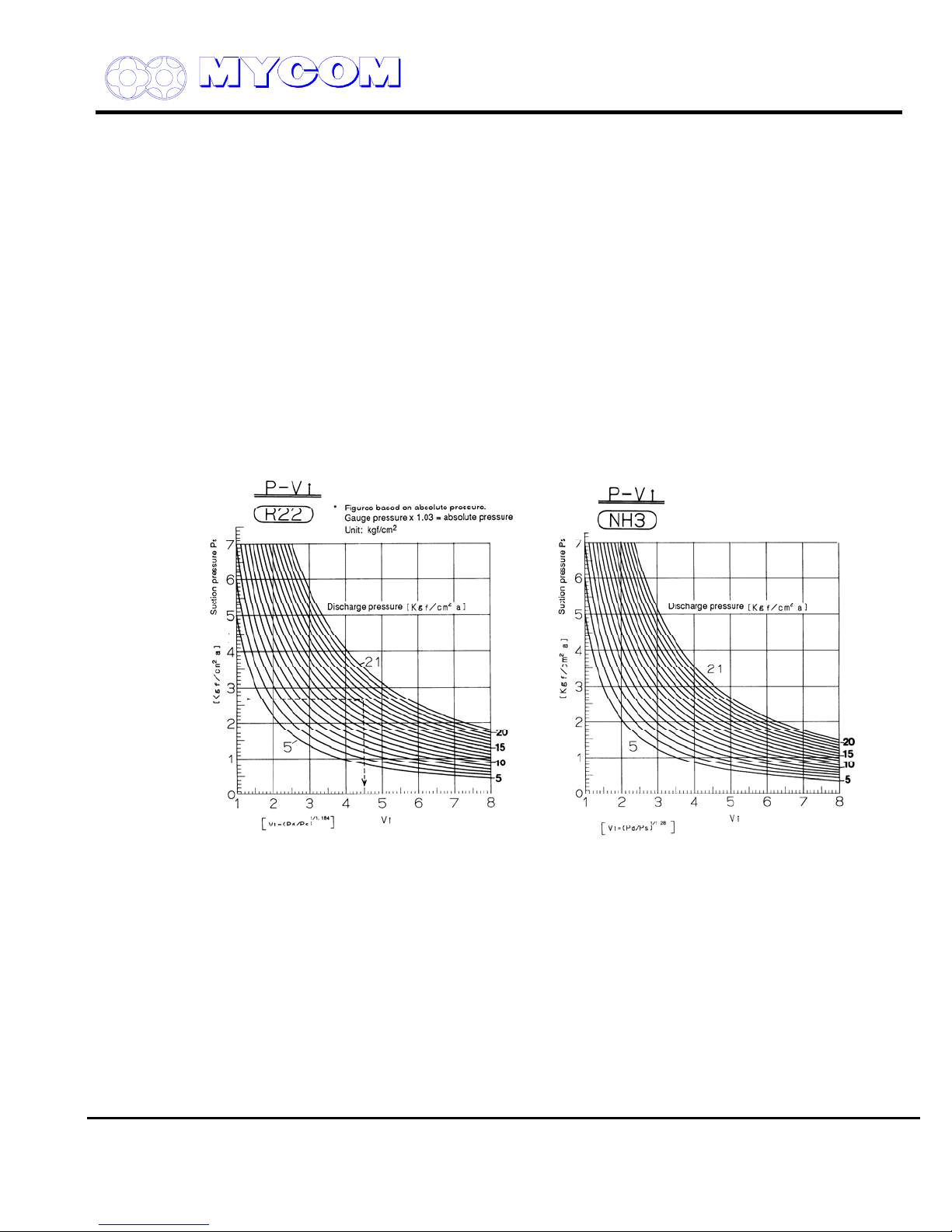
SCREW COMPRESSOR HANDLING MANUAL
a) Determine P
P
= Absolute value of discharge pressure = Discharge gauge pressure + 1.033 kgf/cm
d/Ps
Absolute value of suction pressure Suction gauge pressure + 1.033 kgf/cm
during operation based on the anticipated operating conditions of the system.
d/Ps
2
2
b) Find Vi from the compression ratio
1/k
)
Vi = (P
Vi can be found directly from the graph. (Working pressure is, however, absolute pressure)(Fig. 12)
d/Ps
or Vik = Pd/P
s
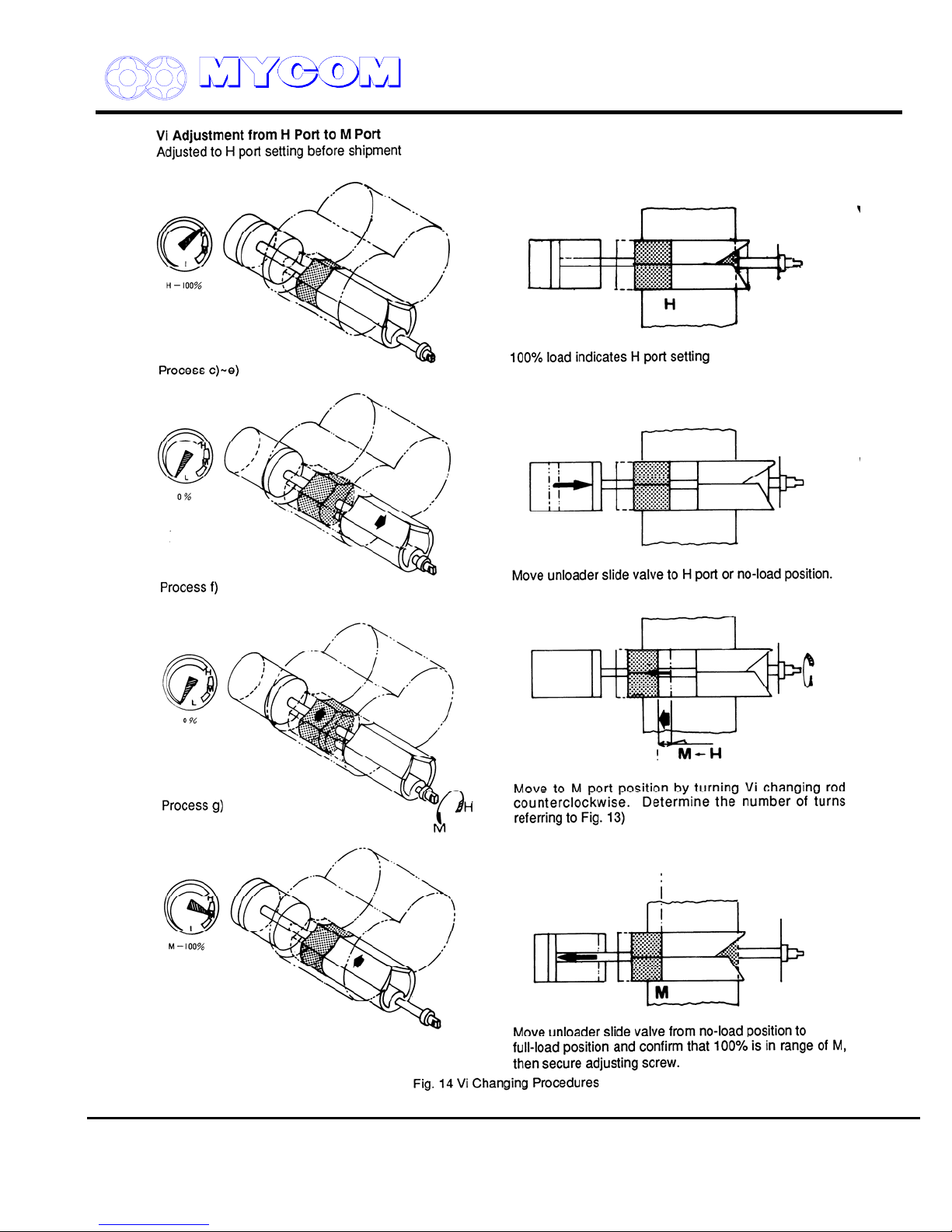
c) After determining the port, set the capacity control mechanism to the unload position.
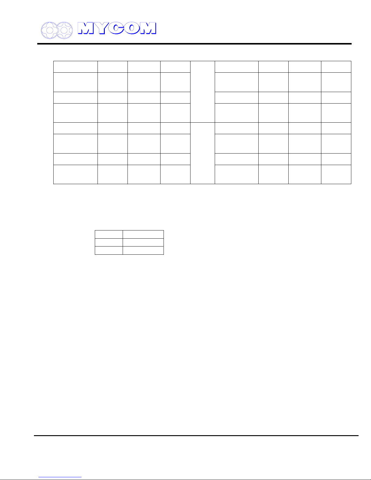
d) Determine the number of turns needed on the Vi changing rod for the particular compressor as
given in Fig. 13.
e) Remove the cap seal on the Vi changing rod and loosen the lock nut.
Turn the Vi changing rod clockwise (CW) and confirm that the variable Vi slide valve is at the
maximum Vi position and that the Vi changing rod does not rotate (unreasonable force should
be avoided when turning the Vi changing rod). (Adjusted to H port configuration before
shipment). In case of medium port (M port), turn the Vi changing rod clockwise (CW) until it
stops and set the variable Vi slide valve to the H port position.
Supersedes all previous version. This information is for reference use only and subject to change without notice
Revision 2 (June 05,2000) Page 9 of 61
V SERIES
REFRIGERATION DIVISION
SCREW COMPRESSOR HANDLING MANUAL
f) Next, record the position of operation start (confirm the position of the stamp on the screw
head).
Turn the Vi changing rod counterclockwise the number of rotations indicated for the particular
compressor as given in Fig. 13.
After adjusting, secure the lock nut (approx. 1/12 of a turn after contact with the casing). When
securing the lock nut, be sure that the Vi changing rod does not rotate out of position.
g) Set the capacity control mechanism to the full load position.
If the needle pointer of the capacity control indicator indicates the specified porti range on the
dial, proper adjustment is confirmed.
An amplitude is provided between the M and H graduations on the indicator dial because the
M and H positions shift depending on whether the compressor is a 160SML, 200 SML or 250
SML model as well as on the rotor length, of which there are nine. Since the graduations on
the dial are common to all models, an amplitude is provided. When the Vi changing rod is
adjusted the correct number of turns and the needle pointer position is within the specified
range, adjustment can be considered correct.
Fig. 12 Graphs for determining Vi from Operating Suction and Discharge Pressure (R22, NH3)
h) Secure the hex head cap nut (453) for the Vi changing rod securely (rotate approx. 1/12 turn
after contacting casing).
Supersedes all previous version. This information is for reference use only and subject to change without notice
Revision 2 (June 05,2000) Page 10 of 61
V SERIES
REFRIGERATION DIVISION
SCREW COMPRESSOR HANDLING MANUAL
H port ĺ M port H port ĺ L port
H ĺ M 160VS* 160VM* 160VL* H ĺ L 160VS* 160VM* 160VL*
Distance
No. of Turns
18mm
7.2
23mm
9.9
27mm
10.8
Distance
No. of Turns
37mm
14.0
45mm
18.0
55mm
22.0
H ĺ M 200VS* 200VM* 200VL* H ĺ L 200VS* 200VM* 200VL*
Distance
No. of Turns
23mm
6.6
28mm
8.0
34mm
9.7
Distance
No. of Turns
46mm
13.0
57mm
16.0
69mm
19.0
H ĺ M 250VS* 250VM* 250VL* H ĺ L 250VS* 250VM* 250VL*
Distance
No. of Turns
29mm
7.3
36.5mm
9.1
43mm
10.8
Distance
No. of Turns
58mm1472.5mm1887mm
21
H ĺ M 320VS* 320VM* 320VL* H ĺ L 320VS* 320VM* 320VL*
Distance
No. of Turns
Fig. 13 Vi Changing Rod Adjustment By Model
Reference:
Dimensions of screw used to change Vi.
Accordingly:
Number of turns x pitch = Variable Vi slide valve distance change
59mm1350mm
11
47mm
10
Distance
No. of Turns
98mm
21.5
98mm
21.5
105mm
23
160v**
200v**
250v**
M20 x P2.5
M30 x P3.5
M36 x P4
Precautions when changing Vi.
1. The Vi should be changed only when the compressor is stopped and the capacity control
mechanism is set to the no-load position.
2. Unreasonable force should not be applied to the mechanism provided on L port and M port
compressors.
3. If the Vi needs to be positioned midway between two different ports, select the best port
referring to the capacity chart. Do not use variable Vi except for L, M and H ports.
4. The Vi should not be changed frequently in an attempt to adjust to small changes in the
compression ratio, which may arise during normal operations. If no substantial change in
operating conditions (e.g., a change in evaporative temperature) is required, the Vi should be
changed only in the autumn and spring following the respective summer and winter seasons.
Supersedes all previous version. This information is for reference use only and subject to change without notice
Revision 2 (June 05,2000) Page 11 of 61
V SERIES
REFRIGERATION DIVISION
SCREW COMPRESSOR HANDLING MANUAL
Supersedes all previous version. This information is for reference use only and subject to change without notice
Revision 2 (June 05,2000) Page 12 of 61

V SERIES
REFRIGERATION DIVISION
1.6 Other Component Mechanisms
a) The radial load of the compressor is absorbed by white meal-lined bearings while the axial
thrust load on the rotors is absorbed by an angular contact ball bearing.
The balance piston of the V-Series compressor M rotor is somewhat larger in diameter than
that of a conventional screw compressor in order to allow for a decrease in the oil pressure
load which is used for pressure difference lubrication.
b) A new, single balance type mechanical shaft seal is used on the drive shaft to protect the shaft
from refrigerant leakage.
The mechanical seal utilizes O-ring packing to allow service with various different refrigerants.
A combination of carbon and metal is used to assure the durability of the frictional parts and
the sealing effect.
c) A cam is provided to indicate the position of the variable Vi slide valve and unloader slide
valve. The capacity control ratio is shown on the dial indicator. Capacity control indication can
be output to a remote indicator using the electric circuit provided.
d) Compressor oil flow
Oil for lubrication and for injection is supplied from a high pressure side oil tank by the
pressure difference with the low pressure side or by an additional pump. Regarding oil
injection, conventional compressors have oil injected into the triangular blow hole in the mating
portion of the unloader slide valve but V-Series compressors utilize a system whereby oil is
supplied from a fixed position on the M rotor side rotor casing.
SCREW COMPRESSOR HANDLING MANUAL
e) Unlike with conventional screw compressors, oil is also supplied to the F rotor side bearing
directly from the suction cover.
Supersedes all previous version. This information is for reference use only and subject to change without notice
Revision 2 (June 05,2000) Page 13 of 61

V SERIES
Oil Flow
REFRIGERATION DIVISION
SCREW COMPRESSOR HANDLING MANUAL
Fig. 15 Schematic Diagram of Lubrication System
Supersedes all previous version. This information is for reference use only and subject to change without notice
Revision 2 (June 05,2000) Page 14 of 61
V SERIES
REFRIGERATION DIVISION
SCREW COMPRESSOR HANDLING MANUAL
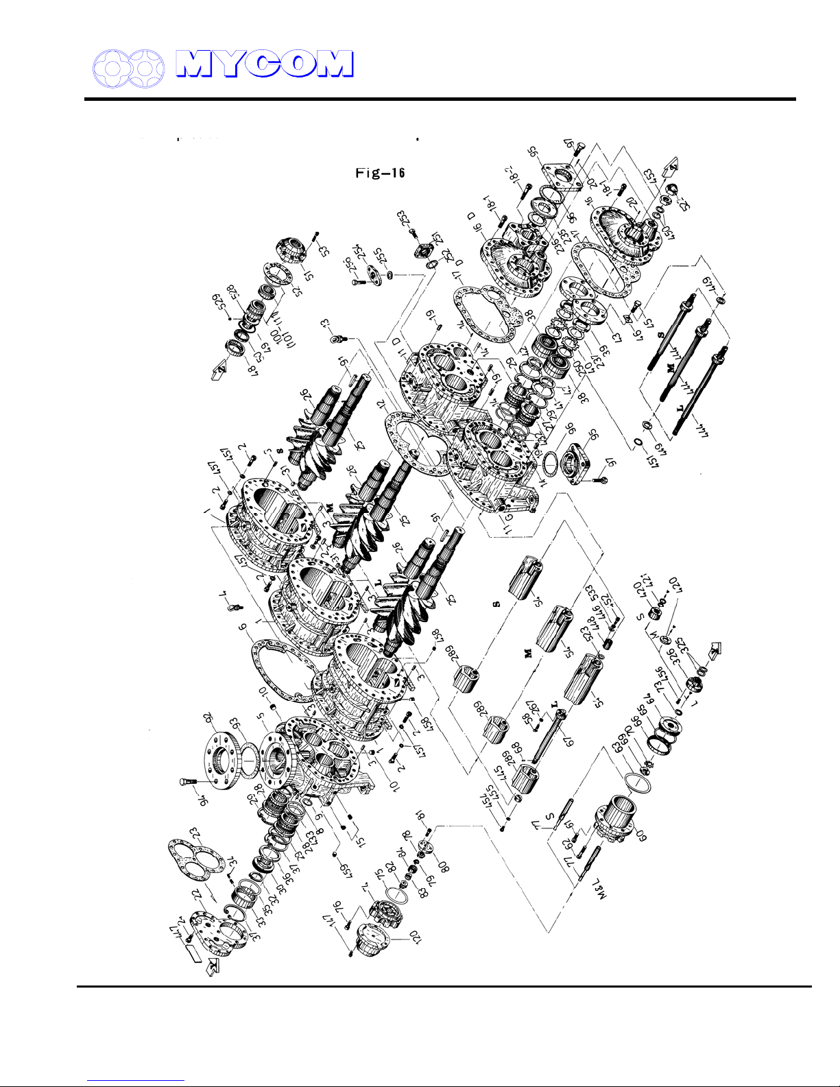
2. Exploded View of V-Series Screw Compressor
Supersedes all previous version. This information is for reference use only and subject to change without notice
Revision 2 (June 05,2000) Page 15 of 61
V SERIES
REFRIGERATION DIVISION
2.1 Parts List
No. Parts Name
1 Main Rotor Casing
2 Hexagon Socket Head Cap Screw
3 Alignment Pin
4 Hanger Bolt
5 Suction Cover
6 Gasket, Suction Cover
8 Spring Pin
9 "O"Ring
10-A Plug
10-B Plug
10-C Plug
10-D Plug
11 Bearing Head
12 Gasket, Bearing Head
13 Hanger Bolt
14 Spring Pin
16 Bearing Cover
17 Gasket, Bearing Cover
18-1 Hexagon Socket Head Cap Screw
18-2 Hexagon Socket Head Cap Screw
19 Alignment Pin
20 Spring Pin
21 Plug
22 Balance Piston Cover
23 Gasket, Balance Piston Cover
24 Hexagon Socket Head Cap Screw
25 Male Rotor
26 Female Rotor
27 Main Bearing
28 Side Bearing
29 Stop Ring
30 Balance Piston
31 Key, Balance Piston
32 Stop Ring
33 Sleeve, Balance Piston
34 Set Screw
35 "O"Ring
36 Spacer
37 Stop Ring
38 Thrust Bearing Assembly
No. Parts Name
39 Lock Nut
40 Lock Washer
41 Spacer, Thrust Bearing Outer Race
42 Spacer, Thrust Bearing Alignment
SCREW COMPRESSOR HANDLING MANUAL
43 Thrust Bearing Gland
45 Hexagon Head Bolt
46 Lock Washer
48 Retainer, Oil Seal
49 "O"Ring
50 Oil Seal
51 Seal Cover
52 Gasket, Seal Cover
53 Hexagon Socket Head Cap Screw
54 Unloader Slide Valve
58 Hexagon Socket Head Cap Screw
60 Unloader Cylinder
61 Hexagon Socket Head Cap Screw
62 Hexagon Socket Head Cap Screw
63 "O"Ring
64 Unloader Piston
65 "O"Ring
66 Cap Seal
67 Push Rod, Unloader Slide Valve
68 Guide Pin
69 Lock Nut
70 Lock Washer
73 "O"Ring
74 Unloader Cover
75 "O"Ring
76 Hexagon Socket Head Cap Screw
77 Unloader Indicator Cam
78 Ball Bearing
81 Hexagon Socket Head Cap Screw
82 "V"Ring
83 Spring
84 Retainer
91 Shaft Key
100 Assembly, Mechanical Seal
120 Assembly, Unloader Indicator
137 Unloader Indicator
237 Torsional Slip Washer
No. Parts Name
250 Washer, Thrust Bearing
267 Spring Washer
289 Vi Slide Stop
325 "O"Ring
326 Gland, "O"Ring
420 Unloader Spacer
421 "O"Ring
432 "O"Ring
Supersedes all previous version. This information is for reference use only and subject to change without notice
Revision 2 (June 05,2000) Page 16 of 61
V SERIES
REFRIGERATION DIVISION
433 "O"Ring
444 Vi Adjusting Rod
445 Washer
446 Vi Square Washer
447 Name Plate
448 Bushing
449 Thrust Washer
450 "O"Ring
451 "O"Ring
452 Hexagon Socket Head Cap Screw
453 Hexagon Nut
454 Hexagon Socket Head Cap Screw
455 Spring Washer
SCREW COMPRESSOR HANDLING MANUAL
456 Hexagon Socket Head Cap Screw
457 Spring Washer
458 Plug
459 Plug
522 Domed Cap Nut
523 "O"Ring
528 Sleeve, Oil Seal
529 Set Screw
533 Spring Washer
605 Plug
No Parts Name
607 Plug
Supersedes all previous version. This information is for reference use only and subject to change without notice
Revision 2 (June 05,2000) Page 17 of 61
V SERIES
REFRIGERATION DIVISION
SCREW COMPRESSOR HANDLING MANUAL
Supersedes all previous version. This information is for reference use only and subject to change without notice
Revision 2 (June 05,2000) Page 18 of 61
V SERIES
REFRIGERATION DIVISION
SCREW COMPRESSOR HANDLING MANUAL
Supersedes all previous version. This information is for reference use only and subject to change without notice
Revision 2 (June 05,2000) Page 19 of 61
 Loading...