

2203M4JE-MY-iS2-N_2017.04.
i-Series Screw Compressor
Instruction Manual
i125S / i125L
i160S / i160M / i160L
CAUTION
Before operating, servicing, or inspecting this product, read this manual thoroughly to
fully understand the cont ents.
Keep this instruction manual in a safe, designated place for future reference whenever
the manual is needed.
Specifications of this product and contents of this manual are subject to change without
prior notice due to technical im pr ovements, and the like.
This manual is applied to each compressor after the serial number
shown below.
i125S: 8750303 i125L: 8770301
i160S: 8710055 i160M: 8720018 i160L: 8730030
2203M4JE-MY-iS2-N_2017.04.
Preface
Screw Compressor i-series
i
Preface
Thank you for purchasing our
i-series screw compressor (hereinafter referred to as "this
product").
This instruction manual (hereinafter referred to as "this manual") provides safety information and
operation and maintenanc e procedures , so that users correct ly understand how t o handle this pr oduct
and, as a result, can use it safely and efficiently.
Before installing or using this product, make sure you read this manual.
Keep this manual in a safe place near this product for quick reference.
Revision History
Title Document No. First edition issue date
i-Series Screw Compressor
Instruction manual
2203M4JE-MY-iS2-N_2017.04.
April 28, 2014
Revision
No.
Issue Date Major contents of revisions
Created
/ approved by:
00 April 28, 2014
Newly is
sued as applicable to the product after May
2014, due to modification of the i-series specifications.
Muta
/ Ikeda, Hirao
01 Sep. 24, 2014 Added models for IEC motor flange specifications.
Amanuma, Kato /
Ikeda, Hirao
02
June 01, 2015
Modified the constitution of Chapter 4 and Chapter 5.
Added the basic multi-packaging points using plural
i-sereis compressors.
Kitahara,
Fujimoto / Ikeda
03
April 30, 2017
Corrected 2.3.1 Standard Specifications, 2.4.3 Parts
Configuration Table . Deleted Contact Information.
Takenouchi,
Ito / Kato

2203M4JE-MY-iS2-N_2017.04.
Warranty and Disclaimer
Screw Compressor i-series
ii
Warranty and Disclaimer
Warranty Clauses
MAYEKAWA shall repair or replace parts of this product for no charge if any failure resulting from
defects in design or m anufacture occurs, und er normal use with th e purpose and method t hat are in
accordance with the specifications of this product and this manual, within the warranty period.
The warranty period is "12 months from factory shipment of this product". If there is a separate
agreement, that agreement shall prevail in principle.
MAYEKAWA is not liable for production or m an-made disaster compensation due to malfunction or
damage of this product.
Disclaimer of Warranty
Although MAYEKAWA warrants the clauses mentioned above, the following clauses are exempted.
Malfunction or damage of this product caused b y natural disaster, or other accidental forces
(such as fire, thunderbolt, windstorm, intense rainfall, flood, tidal wave, earthquake, land
subsidence, etc.).
Malfunction or damage caused by misusage described below.
• Malfunctions, damage, or deteri oration of this product due to abn ormal or improper use
(including improperly storing this product outdoors or under too hot/humid conditions,
unexpected inspections , tests, operations, too frequent liquid flow-back operation*, and
too frequent start-stop cycles, etc.).
• Malfunction or damage c aused by devices or equipm ents not provided by MAYEKAWA
including operation control methods of those devices.
• Malfunction or damage c aused by refrigerants, gases, or refr igerant oils, and operating
conditions (design conditions) not approved for this product.
• Malfunction or damage caused by maintenance or inspection not recommended by
MAYEKAWA.
• Malfunction or damage caused by parts that are not
genuine.
• Malfunction or damage caused by remodeling the product without approval of
MAYEKAWA.
• Malfunction or damage caused by unexpected misusage
"Liquid flow-back operation" is ・・・
Normally, while the compressor suc ks in the refrigerant liquid only after vaporizing it in th e
evaporator, it may directly sucks it in because of the faulty adjustment or failure of the
expansion valve. We call this state of compressor operation "liquid flow-back operation".
No compressor can compress a liquid. The compressor may be damaged should the liquid be
sucked in.

2203M4JE-MY-iS2-N_2017.04.
Important Information
Screw Compressor i-series
iii
Important Information
Intended Use of this Product
This product is a general-p ur pose s c rew compressor for refrigeratio n and c o ld sto r age. Do not use this
product for any other purpos es that are not intended for or which depart f rom the specifications. For
specifications of this product, refer to "2.3 Compressor Specifications".
Please perform the maintenance items described in this manual by using safe and assured procedures.
Important Information for Safe Use of this Product
Although MAYEKAWA has paid a lot of attention to safety measures for this product, all hazards
including potential ha zards caused by human errors, or due to environmental cond itions can not be
anticipated.
As there are too many items to be strictly observed or prohibited when using this product, it is
impossible to inform all of them through t his m anual or war ning lab els. Theref ore, when operat ing this
product, pay extreme caution on personnel safety as well as on items described in this manual.
Important rules for safety work with this product that apply to all workers including managers and
supervisors are listed below.
Please read this manual b efore using this product. Fully understand the instructions provided there,
and be sure to perform the safety procedures described in this manual.
Operation, maintenance, and inspection of this product should be performed by qualified
personnel educated about the fundamentals of this product and trained about hazards
involved and measures to avoid danger.
Do not allow any person other than those educated on the fundamental expertise of this
product and trained about hazards invol ved and m eas ures to avoid dangers to ap proach this
product while it is operating or during maintenance.
Observe all related federal/national and local codes and regulations.
To prevent accidents, do not carry out any operation or maintenance other than those
described in this manual. Do not use this product for any purpose other than intended.
Replace the parts with the
genuine parts.
Not only workers but also m anagers should acti vely participate saf ety and health activities in
the workplace to prevent accidents.
When closing or opening a valve during work , make sure to apply lock out/tagout to prevent
the valve from being accidentally closed or opened during the work.
[Lockout] To lock with a key in order to keep people, except the workers involved, from
operating the product.
“Lockout” m eans disc onnec ting or k eepi ng disc onnec ted m ac hines and d evices b y lock ing their
energy (po wer) sources. Lockout is not just simpl y turning off the power switches to stop the
supply of power, but includes immobilizing them with a key or similar device to keep any blocked
switches from being operated.
Lockout devices are devices such as keys, covers, and latches, to immobilize switches, valves,
opening and closing levers, etc., with a state of being locked.

2203M4JE-MY-iS2-N_2017.04.
Important Information
Screw Compressor i-series
iv
[Tagout] To prevent any inappropriate work by hanging tag plates indicating "work in
progress".
“Tagout” means to clearly indicate, by hanging tag plates, that a device is in lockout and that
operation of the device is prohibited. Tag plates forbidding operation, starting, opening, etc. are
warnings clearl y stating to not operate energ y (power) sources, and ar e not for stopping block ing
devices.
Observe the following precautions when performing maintenance work on electrical control.
Electrical maintenanc e of the pr oduct m ust be perform ed by certif ied/qual ified p ersonnel a nd
only those educated about the electrical control of the product.
Before servicing or insp ecti ng the el ectrical equipm ent or devices , turn "OFF" th e m otor main
power and control power, and perform lock out/tagout to prev ent the power from bein g turned
on during work.
Even when the motor main power and control power are turned "OFF", this product may be turned on if
the power is supplied from outside the package unit in which this product is used. Make sure the power
supply on the power source sid e is shut off, and perform lock out/tagout to prevent the product from
being turned on during work.
About This Manual
This product may be modified without prior notice. Therefore, the appearance of actual
machine may differ fr om the descriptions in th is manual. If you have any questions, contact
our sales offices or service centers. F or each sight of MAYEKAWA, refer to following URL.
http://www.mayekawa.com/about/network/
This manual is in English. I f an y other lan guage is requ ired, it is th e customers’ responsibility
to prepare a manual for safety education and operation instructions.
This manual is copyrighted. Drawings and technical references including this manual shall not,
in whole or part, be copied, photocopied, or reproduced into any electronic medium or
machine-readable form without prior permission from MAYEKAWA.
Photographs or drawings i ncluded in this manual may differ from the appear ance of actual
product.
If this manual is lost or dam aged, immediately request to one of our local sales offices or
service centers for a new m anual. Us ing this pr oduct without the m anual m ay res ult in saf ety
issues.
When you resell this product, be sure to transfer this manual to the next owner.

2203M4JE-MY-iS2-N_2017.04.
Important Information
Screw Compressor i-series
v
Structure of This Manual
Chapter/Section Title Description
Preface Describes the outline of this manual and how to read this manual.
Warranty and Disclaimer
Describes what MAYEKAWA warrants and what
are covered by the
warranties.
Warranty exemption is stated as disclaimer.
Important Information Describes important information related to this product and this manual.
1. Safety
Describes safety information for the worker, safety rules for this product,
and management details regar ding the work safety that is r equired for
handling this product.
2. Compressor
Specifications and
Configuration
Describes the main com ponents of this product, func tional
information,
specification, operating limits, drawings, and parts list.
3. Installation Describes the installation procedure of this product.
4. Compressor and Package
Unit Operation
Describes the precautions for operating this product
and the package
unit..
5. Maintenance and
Inspection
Describes sections and period for inspecting, and assembly and
disassembly of this product.
6. Troubleshooting
Describes troubl
eshooting methods for this product in case problems
occur during operation of this product.
7. Related Documents List of disassembly tools for i-series compressor, and other information
Appendix 1 :
Packaging Points 1
Describes basic points for the design and manufacture of a i-
series
compressor package unit.
Appendix 2:
Packaging Points 2
Describes basic multi-packaging points using plural i-sereis
compressors.

2203M4JE-MY-iS2-N_2017.04.
Table of Contents
Screw Compressor i-series
vi
Table of Contents
Preface .................................................................................................................. ⅰ
Revision History ................................................................................................... ⅰ
Warranty and Disclaimer ...................................................................................... ⅱ
Important Information .......................................................................................... ⅲ
Intended Use of This Product ........................................................................................... ⅲ
Important Information for Safe Use of This Product .......................................................... ⅲ
About This Manual ............................................................................................................. ⅳ
Structure of This Manual .................................................................................................... ⅴ
Table of Contents ................................................................................................. ⅵ
1 Safety
1.1 Strict Requirements and Prohibitions ....................................................... 1-1
1.1.1 Strict Requirements (Do's) ................................................................................... 1-1
1.1.1.1 Do's on Operation ........................................................................................ 1-1
1.1.1.2 Do's on Maintenance ................................................................................... 1-1
1.1.1.3 Do's on Lockout/Tagout after Shutting Off the Power ................................. 1-2
1.1.1.4 Do's about Personal Protective Gear .......................................................... 1-2
1.1.1.5 Do's about the Handling of Hazardous and Toxic Substances.................... 1-2
1.1.1.6 Do's about Handling Emergency Situations ................................................ 1-2
1.1.1.7 Do's about Waste Oil, Fluid, and Materials ................................................. 1-2
1.1.1.8 Other Do's .................................................................................................... 1-2
1.1.2 Prohibitions (Don'ts) ............................................................................................ 1-3
1.2 Warnings ..................................................................................................... 1-3
1.3 Residual Risks ............................................................................................ 1-4
1.4 Safety Devices ............................................................................................ 1-6
1.4.1 Emergency Stop Button ....................................................................................... 1-6
1.4.2 Circuit Breakers of Motor Main Power and Control Power
(with Lockout/Tagout Mechanism) ....................................................................... 1-6
1.4.3 Compressor Protective Devices ................................................................ 1-7
Chapter 2 Compressor Specifications and Configuration
2.1 Features of
i-Series Compressor ........................................ 2-1
2.2 Model Designation of the Compressor ..................................................... 2-1
2.3 Compressor Specifications ....................................................................... 2-2
2.3.1 Standard Specifications ....................................................................................... 2-2
2.3.2 Operation limits .................................................................................................... 2-3

2203M4JE-MY-iS2-N_2017.04.
Table of Contents
Screw Compressor i-series
vii
2.3.3 Alarm Set Values ................................................................................................. 2-4
2.3.4 Outer Dimensions ................................................................................................ 2-5
2.4 Configuration of Compressor .................................................................. 2-18
2.4.1 Secti ona l Vie ws ................................................................................................. 2-18
2.4.2 Exploded Views ................................................................................................. 2-24
2.4.3 Parts Configuration Table .................................................................................. 2-26
2.5 Mechanisms .............................................................................................. 2-33
2.5.1 Basics of the Screw Compressor ...................................................................... 2-33
2.5.2 Sucti on Pr oces s ................................................................................................. 2-33
2.5.3 Compression Process ........................................................................................ 2-34
2.5.4 Disc har ge Proc es s ............................................................................................. 2-34
2.5.5 About Volume Ratio (Vi) .................................................................................... 2-34
2.5.6 Capac ity Control Mechanism ............................................................................. 2-36
Chapter 3 Installation
3.1 General Precautions for Installation ......................................................... 3-1
3.2 Installation Works....................................................................................... 3-1
3.2.1 Unpacking ............................................................................................................ 3-1
3.2.2 Storage ................................................................................................................ 3-1
3.2.3 Transportation ...................................................................................................... 3-1
3.2.4 Preparation for Installation ................................................................................... 3-3
3.2.5 Installation ............................................................................................................ 3-3
3.2.5.1 Piping Connection ....................................................................................... 3-3
3.2.5.2 Equipment and Devices for Protection of the Compressor ......................... 3-4
3.2.6 Airtightness Test .................................................................................................. 3-4
3.2.7 Lubricating Oil Charge ......................................................................................... 3-4
3.2.7.1 Initial Charge of Lubricating OIL .................................................................. 3-5
3.2.7.2 Additional Charge of Lubricating Oil ............................................................ 3-5
3.2.8 Charge of Refrigerant .......................................................................................... 3-5
3.2.9 Check after Installation ........................................................................................ 3-5
Chapter 4 Compressor and Package Unit Operation
4.1 Lubricating Oil (Refrigerant Oil) ................................................................ 4-1
4.1.1 Precautions for Selecting the Lubricating Oil....................................................... 4-1
4.1.2 Recommended Lubricating O ils .......................................................................... 4-2
4.1.2.1 Recommended Lubricating Oils for Ammonia Refrigerant .......................... 4-2
4.1.2.2 Oils for Systems Using Hydrofluorocarbon (HFC) Refrigerants .................. 4-3
4.1.3 Change of Lubricating Oil Brand ......................................................................... 4-3
4.1.4 Precautions for Handling Lubricating Oil ............................................................. 4-4
4.1.5 Lubricating Oil Management Criteria ................................................................... 4-4
4.1.6 Lubricating Oil Replacement Timing .................................................................... 4-5

2203M4JE-MY-iS2-N_2017.04.
Table of Contents
Screw Compressor i-series
viii
4.1.6.1 After Starting the Initial Operation .............................................................. 4-5
4.1.6.2 During Normal Operation ........................................................................... 4-5
4.2 Precautions for Operation ......................................................................... 4-6
4.2.1 Prevention of Liquid Flow-back ........................................................................... 4-6
4.2.2 Purging of Non-Condensable Gases ................................................................... 4-6
4.3 When Stopping the Compressor for a Long Time .................................... 4-7
Chapter 5 Maintenance and Inspection
5.1 Precautions for Maintenance and Inspection ........................................... 5-1
5.2 Maintenance and Inspection List .............................................................. 5-3
5.2.1 Dai l y Management ............................................................................................... 5-3
5.2.2 Periodic Inspection .............................................................................................. 5-5
5.2.3 Guidelines for Compressor Overhaul Interval ..................................................... 5-6
5.3 Compressor Disassembly Preparation ..................................................... 5-7
5.3.1 Disassembly Tools and Work Place .................................................................... 5-7
5.3.2 Replacement Parts .............................................................................................. 5-8
5.3.3 Refrigerant Gas Treatment ................................................................................ 5-10
5.3.3.1 Valves Used ............................................................................................... 5-10
5.3.3.2 Refrigerant Gas Recovery ......................................................................... 5-10
5.3.4 Removing Parts Connected to the Unit ............................................................. 5-11
5.3.5 Removing and Lifting the Compressor .............................................................. 5-11
5.3.6 Removing Oil from Compressor ........................................................................ 5-11
5.4 Disassembly and Inspection ................................................................... 5-12
5.4.1 Shaft Seal Block ................................................................................................ 5-12
5.4.1.1 Disassembly .............................................................................................. 5-12
5.4.1.2 Inspection .................................................................................................. 5-13
5.4.2 Bear ing Co ver .................................................................................................... 5-14
5.4.2.1 Disassembly .............................................................................................. 5-14
5.4.2.2 Inspection ................................................................................................... 5-14
5.4.3 Balanc e Pist on ................................................................................................... 5-15
5.4.3.1 Disassembly .............................................................................................. 5-15
5.4.3.2 Inspection .................................................................................................. 5-15
5.4.4 End Cover .......................................................................................................... 5-15
5.4.5 Thrust Bearing Block ......................................................................................... 5-16
5.4.5.1 Disassembly .............................................................................................. 5-16
5.4.5.2 Inspection .................................................................................................. 5-16
5.4.6 Bear ing Hea d ..................................................................................................... 5-17
5.4.6.1 Disassembly .............................................................................................. 5-17
5.4.6.2 Inspection .................................................................................................. 5-17
5.4.7 Rotors ................................................................................................................ 5-17
5.4.7.1 Disassembly .............................................................................................. 5-17
5.4.7.2 Inspection .................................................................................................. 5-17
5.4.8 Radial Be ar ings ................................................................................................. 5-18
5.4.8.1 Disassembly .............................................................................................. 5-18

2203M4JE-MY-iS2-N_2017.04.
Table of Contents
Screw Compressor i-series
ix
5.4.8.2 Inspection .................................................................................................. 5-18
5.4.9 Sucti on Str ai ner and Check Valve ..................................................................... 5-18
5.4.9.1a Disassembly (i125*) ................................................................................... 5-18
5.4.9.1b Disassembly (i160*) ................................................................................... 5-18
5.4.9.2 Inspection .................................................................................................. 5-19
5.4.10 Unloader ............................................................................................................ 5-19
5.4.10.1 Disassembly .............................................................................................. 5-19
5.4.10.2 Inspection .................................................................................................. 5-19
5.5 Reassembly .............................................................................................. 5-20
5.5.1 Unloader ............................................................................................................ 5-21
5.5.2 Rotor and Inner Race of Radial Bearing ............................................................ 5-21
5.5.3 Bear ing Hea d ..................................................................................................... 5-22
5.5.4 Outer Race of Radial Bearing ............................................................................ 5-22
5.5.5 Suction Strainer and Check Valve ..................................................................... 5-23
5.5.5.1 i125*........................................................................................................... 5-23
5.5.5.2 i160*........................................................................................................... 5-23
5.5.6 Adjustment of Thrust Bearing and End Clearance ............................................ 5-24
5.5.6.1 End Clearance Measurement .................................................................... 5-26
5.5.6.2 End Clearance Adjustment ........................................................................ 5-27
5.5.6.3 Tightening after End Clearance Adjustment .............................................. 5-27
5.5.7 Balanc e Pist on ................................................................................................... 5-28
5.5.8 Bear ing Co ver .................................................................................................... 5-28
5.5.9 Shaft Seal Block ................................................................................................ 5-29
5.5.10 End Cover .......................................................................................................... 5-31
Chapter 6 Troubleshooting
01: Compressor does not start up ................................................................................ 6-1
02: Compressor stops immediately after startup .......................................................... 6-1
03: Abnormally low pressure (decrease of suction pressure) ...................................... 6-2
04: Low oil pressure (low oil supply pressure) ............................................................. 6-2
05: Abnormally high pressure (abnormal discharge pressure) .................................... 6-3
06: Discharge temperature is abnormally high ............................................................. 6-4
07: Leak from mechanical seal part ............................................................................. 6-6
08: Squeaking sound from mechanical seal ................................................................ 6-6
09: Capacity control malfunction .................................................................................. 6-6
10: Compressor generates abnormal vibration and/or sound ...................................... 6-6

2203M4JE-MY-iS2-N_2017.04.
Table of Contents
Screw Compressor i-series
x
Chapter 7 Related Documents
7.1 Tightening Angles for Lock Nuts .............................................................. 7-1
7.2 Disassembly Tools ..................................................................................... 7-2
7.3 Flange Motor and Connection Flange Size ............................................. 7-3
Appendix 1: Basic Points for Design and Manufacturing for the
Compressor Package
1-1 Basic Flow of the Package Unit ........................................................... Appendix 1-1
1-2 Basic Flow of the Oil Cooler ................................................................ Appendix 1-2
1-3 Oil Temperature Control ...................................................................... Appendix 1-3
1-4 Economizer .......................................................................................... Appendix 1-3
1-5 Oil Separator ....................................................................................... Appendix 1-4
1-6 Protection Devices ............................................................................... Appendix 1-4
1-7 Power Supply and Control Devices ..................................................... Appendix 1-5
Appendix 2: Basic Points for Design and Manufacturing for the
Compressors Multi-package
2-1 Preface ................................................................................................ Appendix 2-1
2-2 Reference Flow and Configuration Components for Multi-package ... Appendix 2-1
2-2-1 Package Flow Representative Example ......................................... Appendix 2-1
2-2-2 Oil Separator ................................................................................... Appendix 2-2
2-2-3 Pressure Regulator for Differential Oil Supply Press ure ............... Appendix 2-2
2-2-4 Oil Cooler ........................................................................................ Appendix 2-2
2-2-5 Oil Filter and Oil Line ....................................................................... Appendix 2-2
2-2-6 Stop Valves and Safety Valves ....................................................... Appendix 2-2
2-3 Economizer .......................................................................................... Appendix 2-3
2-4 Protection Devices and Control Devicess ........................................... Appendix 2-3

2203M4JE-MY-iS2-N_2017.04.
Chapter 1 Safety
Screw Compressor i-series 1.1 Strict Requirements and Prohibitions
1-1
Chapter 1 Safety
1.1 Strict Requirements and Prohibitions
1.1.1 Strict Requirements (Do’s)
1.1.1.1 Do’s on Operation
Make sure to attach safety and protective devices to the package unit.
The safety devices and protection systems must be regularly checked for their normal
operation.
If any safety device or protection system does not function normally or this product operates in
an abnormal manner, immediately stop the work and contact your supervisor. When the
system is to be restarted, you must observe the decision and instruction of the supervisor.
If this product has stopped operation due to an unknown cause, immediately contact your
supervisor. Before restarting the system , you must seek the decision and instruction of the
supervisor.
Depending on the type of refrigerant used, its leakage may generate a bad smell or poisonous
gas. Be sure to sufficiently ventilate the room while the machine is operated.
Regarding the characteristics of the refrigerant and lubricating oil, e.g., corrosiveness,
degradability, and toxicity, be sure to obtain the Safety Data Sheet (SDS) of the m and follow
the instructions given.
When this produc t is not to be used for some peri od of time, close the suction (side) and
discharge (side) stop valves and shut off the m otor power source, heat er power, and control
power.
1.1.1.2 Do’s on Maintenance
Prepare work procedures based on a work plan. Be sure to perform danger forecasting before
starting the work.
If two or more peo ple are to work together, be sure to mutuall y check the work details and
procedures before the work. During the work, always keep track of the other workers’ actions.
Before working on any troubleshooting during operation, before setting up this product, before
cleaning work, and before conducting maintenance or inspec ti on wor k, be sure to shut off the
motor power source, control power, and power to other equipment, perform lock-out and
tag-out procedur es, and take effective measures to p revent any accidental power -on during
the work.
Before working on any troubleshooting during operation, before setting up this product, before
cleaning work, and bef ore conducting m aintenance or inspection work, be sure t o check that
the internal pressure of this product and the refrigeration/cold storage unit is at the
atmospheric pressure.
Depending on the t ype of refrigerant used, it ma y generate a bad smell or poiso nous gas or
could cause an oxygen deficient atmosphere. Before starting the work , measure the ox ygen
content in the work area, as appropriate, and provide sufficient ventilation. The ventilation
must be continued steadily until the work is completed.
For the properties of refrigerant and lubricating oil (corrosiveness, decomposability or toxicity),
be sure to obtain the Safety Data Sheet (SDS) and follow the relevant information.
After work, the tools us ed must be returned to the predefined locat ion. Be sure not to leave
them inside the package unit.

2203M4JE-MY-iS2-N_2017.04.
Chapter 1 Safety
Screw Compressor i-series 1.1 Strict Requirements and Prohibitions
1-2
1.1.1.3 Do’s on Lockout/Tagout afte r Shutting Off the Power
A lock-out/tag-out mechanism must be installed for the main circuit breakers that supply power
to the motor and po wer to the control system . T he lock-out/tag-out after power do w n is a v er y
effective means to ensur e t he s af et y wh en two or more work ers ar e work ing on t he system at
the same time, as it can prevent p ossible i njury of workers t hat ma y be caused b y accidenta l
power-on of the driving source by one of the workers.
If there is a risk of danger, especially during cleaning, maintenance/inspection, or
troubleshooting work , be sure to l et the work ers per form the lock -out/tag-out pr ocedures after
the motor main power and control power has been shut off.
Because the workers m ay neglect to perform the lock-out/tag-out proced ures or cut-off the
power in the following situations, be sure to instruct them to strictly follow the correct
procedure by clearly identifying the work that require lock-out/tag-out and the reasons why it is
needed.
• As it is a cumbers ome task for the workers to cut off the motor m ain power and control
power and use lock -out/tag-out devices before starting the w ork , they m ight negl ec t to do
it.
• The workers m ight determ ine by th em selves th at it sh ould b e OK j ust to c ut off th e m otor
main power and control power, and not use any lock-out/tag-out devices.
1.1.1.4 Do’s about Personal Protective Gear
Prepare and use protective gear com pl ying wit h the safety standards of the regulations.
Check the function of each protective gear before using.
Wear designated clothes such as work outfits, with their cuffs tightly closed.
Do not wear an y neck ties or jewelry as there is a ris k of being entangled by a movable part or
rotating part. Put on a helmet as your hair may get entangled.
Do not have anything in your pocket to prevent objects from falling into the machine.
1.1.1.5 Do’s about Handling of Hazardous and Toxic Substances
Obtain Safety Data Sheet (SDS) from manufacturers of hazardous and toxic substances.
Check the MSDS and fol low the han dling instr uctions recomm ended b y the manuf acturers to
handle and store those substances.
1.1.1.6 Do’s about Handling Emergency Situations
Formulate an emer gency action plan complying with the regulatio ns, and post it on a safe
place.
1.1.1.7 Do’s about Waste Oil, Fluid, and Materials
Disposing of refrigerant and oil used for this product are subject to a number of regulations for
the environmental protecti on purposes. Follow the local, state, federal acts and regula tions
and your company's rules when disposing of such waste oil, fluid and materials.
1.1.1.8 Other Do’s
Keep clean the floor around the entire package unit. Provide a safety passage.
Walk only on the areas set up as a work f loor. Also, do not lea ve too ls and c lea ning sol utions
in that area.
If water or oil is spi lled on this pr oduct or the f loor, immediately wipe it off to pr event work ers
from slipping and getting injured.
2203M4JE-MY-iS2-N_2017.04.
Chapter 1 Safety
Screw Compressor i-series 1.2 Warnings
1-3
1.1.2 Prohibitions (Don’ts)
Do not remove or relocate any safety device, including electrical interfaces.
Do not disable any safety device by short-c irc ui tin g or bypassing with out any permission.
Do not leave this pro duct unsafe and unattended, b y removing a safet y cover or some other
measures.
Do not touch, clean or lubricate any part of this product which is moving.
Do not touch rela ys or electr ic systems such as terminal b lock with bare hands when t urning
on the power.
1.2 Warnings
The warning messages described in this manual warn dangerous situations that may arise during work
by using the following four categories.
Neglecting such warnings may cause accidents, resulting in personal injury or even death.
Also, this product or its auxili ary equipment may be heavily damaged. T herefore, be sure to always
observe the instructions of the warnings.
Table 1-1
Types and Meanings of Warnings
Symbol Meaning
Indicates that there is a high risk of death or severe injury if it is not avoided.
Indicates that there is a potential risk of death or severe injury if it is not avoided.
Indicates that there is a risk of light or medium injury if it is not avoided.
Indicates that there is a potential risk of property damage if it is not avoided.

2203M4JE-MY-iS2-N_2017.04.
Chapter 1 Safety
Screw Compressor i-series 1.3 Residual Risks
1-4
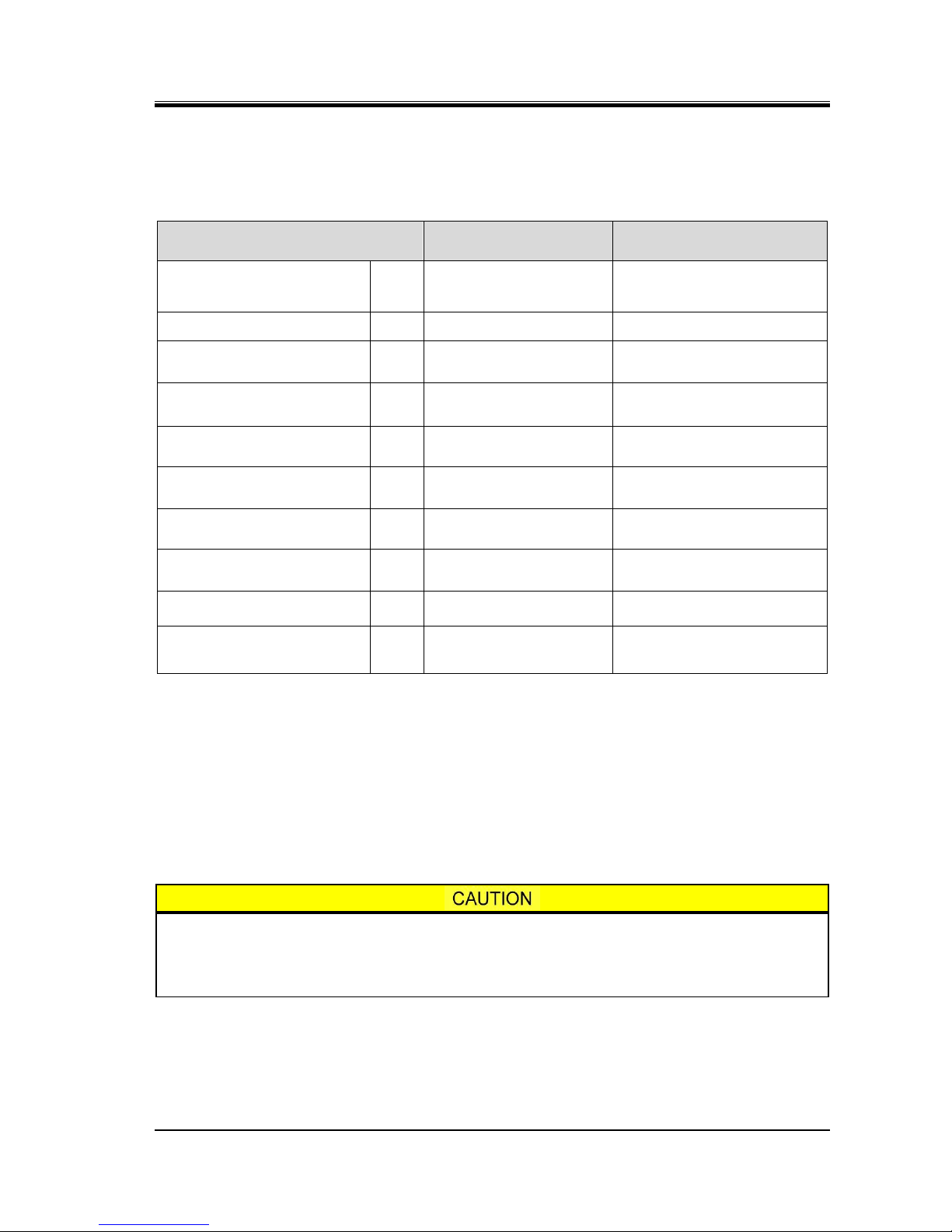
1.3 Residual Risks
The following inform ation assumes that this pr oduct is operated or i nspected/maintained as part of a
general package unit for refrigeration/cold storage. It is impossible to predict all the risk sources
involved in actual use of the package unit.
Devise appropriate countermeasures for hazardous sources in your systems.
Table 1-2
Hazardous Sources
Hazardous
sources
Predicted hazard
Measures to be taken
in operation
Countermeasures in
cleaning, inspection,
and parts replacement
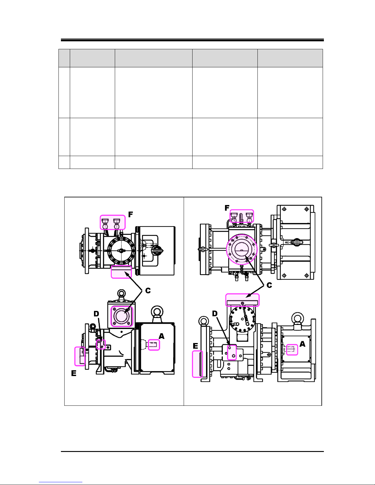
A
Motor and
compressor
coupling
Caught in or entangled in
due to contact
Install cover on the
opening of coupling,
or prohibit opening.
Keep away.
Turn off motor main
power and control
power, and conduct
lockout/tagout.
B
Motor
terminals
Electric shock caused by
contact with live wires or
electrical leakage
Keep away.
Do not open terminal
boxes.
Do not touch
terminal boxes.
Turn off motor main
power and control
power, and conduct
lockout/tagout.
C
Compressor
suction casing
Frostbite due to contact
Contact with or inhalation
of hazardous substances
generated by leakage of
refrigerant or the like
Keep away and do
not touch.
Wear protective
gear.
Detect gas leakage.
Wear protective
gear.
Work under room
temperature.
D
Compressor
economizer
and/or liquid
injection port
around and
piping
Burn injury due to contact
Contact with or inhalation
of hazardous substances
generated by leakage or
spout of refrigerant or the
like
Keep away and do
not touch.
Wear protective
gear.
Detect gas leakage.
Wear protective
gear.
Work at a
temperature of not
higher than 40°C.
E
Compressor
discharge
casing and
discharge
piping
Burn injury due to contact
Contact with or inhalation
of hazardous substances
generated by leakage or
spout of refrigerant or the
like
Keep away and do
not touch.
Wear protective
gear.
Detect gas leakage.
Wear protective
gear.
Work at a
temperature of not
higher than 40°C.
F
Solenoid valve
for controlling
compressor
capacity
Electric shock caused by
contact with live wires or
electrical leakage
Install protective
cover on terminals,
and prohibit
opening.
Keep away and do
not touch.
Wear protective
gear.
Turn off each
breaker and the
control power, and
conduct
lockout/tagout.
Wear protective
gear.
G
Package Unit
Check valve,
service valve
and joint in
each section
Contact with or inhalation
of hazardous substances
generated by mishandling
or leakage
Frostbite or burn due to
contact
Sufficient ventilation
Indicate valve
open/close state.
Keep away and do
not touch.
Wear protective
gear.
Sufficient ventilation
Wear protective
gear.
Tagout for controlled
valve
H
Package Unit
Solenoid valve
or motor
operated
valve
Electric shock caused by
contact with live wires or
electrical leakage
Pinched due to contact
with driving part
Install protective
cover on terminals,
and prohibit
opening.
Keep away and do
not touch.
Wear protective
gear.
Turn off each
breaker and the
control power, and
conduct
lockout/tagout.
Wear protective
gear.
2203M4JE-MY-iS2-N_2017.04.
Chapter 1 Safety
Screw Compressor i-series 1.3 Residual Risks
1-5
Hazardous
sources
Predicted hazard
Measures to be taken
in operation
Countermeasures in
cleaning, inspection,
and parts replacement
I
Package Unit
Electric
components in
each part (oil
heater,
protective
device, etc.)
Electric shock caused by
contact with live wires or
electrical leakage
Pinched due to contact
with driving part
Install protective
cover on terminals,
and prohibit
opening.
Keep away and do
not touch.
Wear protective
gear.
Turn off each
breaker and the
control power, and
conduct
lockout/tagout.
Wear protective
gear.
J
Package Unit
Oil drain
Contact with hazardous
substances generated by
leakage or spout
Burn caused by contact
with high-temperature
fluid
Sufficient ventilation
Keep away and do
not touch.
Wear protective
gear.
Sufficient ventilation
Wear protective
gear.
Work at a
temperature of not
higher than 40°C.
K
Noises
Damage caused by noise
Wear protective
gear.
—
i125L with Spacer for NEMA i160L with Spacer for NEMA
(example) (example)
Figure 1-1 Locations of Hazardous sources (Compressor)
2203M4JE-MY-iS2-N_2017.04.
Chapter 1 Safety
Screw Compressor i-series 1.4 Safety Devices
1-6
1.4 Safety Devices
For safe use and protection of this produc t, make sure to attach safet y devices to this produc t in
accordance with the regulations and the following instructions.
Safety devices cannot be kept in normal condition unless inspected and maintained at regular
intervals. Their maintenance and inspection need to be performed as an important part of the
maintenance/inspectio n work project. Provide users of this product with necessary information on
the safety devices, for example, types of the safety devices, installation position, function, and
inspection method of safety related devices.
Check the safety devices after turning on the power and before operation of this
product. If they do not operat e normally, immediately take countermeasures.
1.4.1 Emergency Stop Button
Overview/Function/Purpose
The emergency stop buttons are used for emergency shutdown of this product when an emergency
situation arises.
Installation Positions
On the control board and in the operation control room
Stop/Restoration Methods
The operating procedures for the emergency stop button, i.e., how to stop the operation and
restore the normal operatin g c ondit io n, must be clearly defined and the inf ormation provided to the
user of this product.
Inspection Method/Interval
The emergency stop buttons mus t be tested befor e commissioning a nd must also be periodicall y
re-tested after that.
The inspection procedures and the inspection interval for the emergency stop button must be
clearly defined and the information provided to the user of this product
1.4.2 Circuit Breakers of Motor Main Power and Control Power
(with Lockout/Tagout Mechanism)
Overview/Function/Purpose
Turn off the main motor and control power, and if there is an y possibility of danger during work
(especially during cle aning, maintenance, inspection, or tr oubleshooting), lockout/tagout devices
must be used on the br eak ers of the m ain m otor and cont rol po wers t o prevent injuries to work ers
in case the power is turned on accidentally during work .
Methods of Performing and Releasing Lockout/Tagout
Make sure to clearly notify methods of performing and releasing lockout/tagout referring to the
regulations created by Occupational Safet y & Health Administration (OSHA) or local governing
body.
Inspection Method/Interval
The inspection procedures and the inspection interval for the lockout/tagout devices must be clearly
defined and the information provided to the user of this product.

2203M4JE-MY-iS2-N_2017.04.
Chapter 1 Safety
Screw Compressor i-series 1.4 Safety Devices
1-7
1.4.3 Compressor Protective Devices
Be sure to adjust the set values and check operation of the protective devices before
the commissioning.
Install necessary protection devices shown in section 2.3.3 "Alarm Set Values" in this manual chapter 2.
Also, install the following protection devices that are not indicate in section 2.3.3, as occasion
demands.
• Protection from motor over current (OCR)
This device activates an d applies appropr iate contro l when the c urrent e qual to or higher t han
the set level flows. In some cases, this device stops the compressor operation.
For more information about setting and installation of this device, please refer to the instruction
manual of the motor.
• Protection from oil level decrease
In case of the oi l supp ly by different ial pr essure, install a prot ection device to the oil separator
for protect form oil level decrease. Since there is a possibility that alarm for protection from
lubricating differential press ure decr ease do es not act ivat e even if the amount of lubricat ing oil
is insufficient.
• No Water Alarm
If you use water cooling oil cooler and/or water cooling condenser, a suspension of water
supply protection is necessary.
For more inform ation about setting and install ation of this protectio n d ev ice, pl eas e r ef er to the
instruction manual of the motor or the like used in the cooling water system.
Connection Positions and Settings
Specify the connection position and set ting f or e ach co m pressor protecti ve de vice, an d m ake s ure
to provide users of this product with them.
Inspection Method/Interval
Compressor protect ive devices require operat ion tests and co nfirmation of the settings c alibration
before commissioning as well as at regular intervals.
Specify the inspect ion methods/inter vals of the com pressor protect ion devices, and m ake sure to
provide users of this product with such information.
In the operation test, check that alarms and switches operate normally by using
devices such as pressure tester. Do not operate the compressor with all the valves
closed, or in any other dangerous conditions.
If the protection from oil pressure (OP) or high pressure (HP) activates, do not restar t
operation until the cause of activation is remove d.
2203M4-JE-MY-iS2-N_2017.04.
Chapter 2 Compressor Specifications and Configuration
Screw Compressor i-series 2.1 Features of i-Series Compressor
2-1
Chapter 2 Compressor Specif i c a t ions and Configuration
2.1 Features of
i-series Compressor
i-series compressor enables designers to design highly reliable and most compact
refrigerating unit. It has a lot of features.
Centering is made unnecessary by mounting the motor using a flange.
By mounting the motor using a flange eliminates the need of the troublesome motor centering before
starting the equipment.
Suction strainer and check valve built-in compressor
This compressor has built-in suction strainer and check valve which enable easy maintenance.
No oil pump required in differential pressure oil supply system
This compressor em ploys roller bearings which let lubrication oil res erved in part even when the
machine is stopped. Ac cordingly, no lubrication failure will occur ev en with differential press ure oil
supply system which has no oil pump installed.
3-step (100%, 75%, 50%) unloader
As it has a 3-step (100%, 75%, 50%) unloader built-in, flow adjustment can be done easily.
In addition, inverter-controlled speed control is available.
High efficiency, and low vibration and noise
Use of original screw rotor profile attains high efficiency, and low vibration and noise.
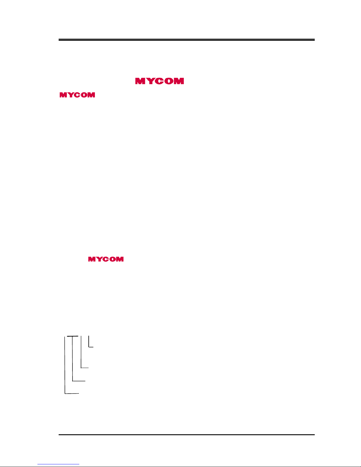
2.2 Model Designation of the Compressor
This manual describes i125*-* and i160*-* models.
The meaning of the type designation, which is engraved on the MODEL column of the compressor
nameplate, is as follows.
i 1 2 5 * - *
Specifications of Vi (volume ratio) of the discharge port, which is L (Vi=2.63), M (Vi=3.65)
or H (Vi=5.80)
Specifications of rotor length, which is S or L (i125) and S, M or L (i160)
Rotor diameter, which is 125 or 160
Indicates i-series.
2203M4-JE-MY-iS2-N_2017.04.
Chapter 2 Compressor Specifications and Configuration
Screw Compressor i-series 2.3 Compressor Specifications
2-2
2.3 Compressor Specifications
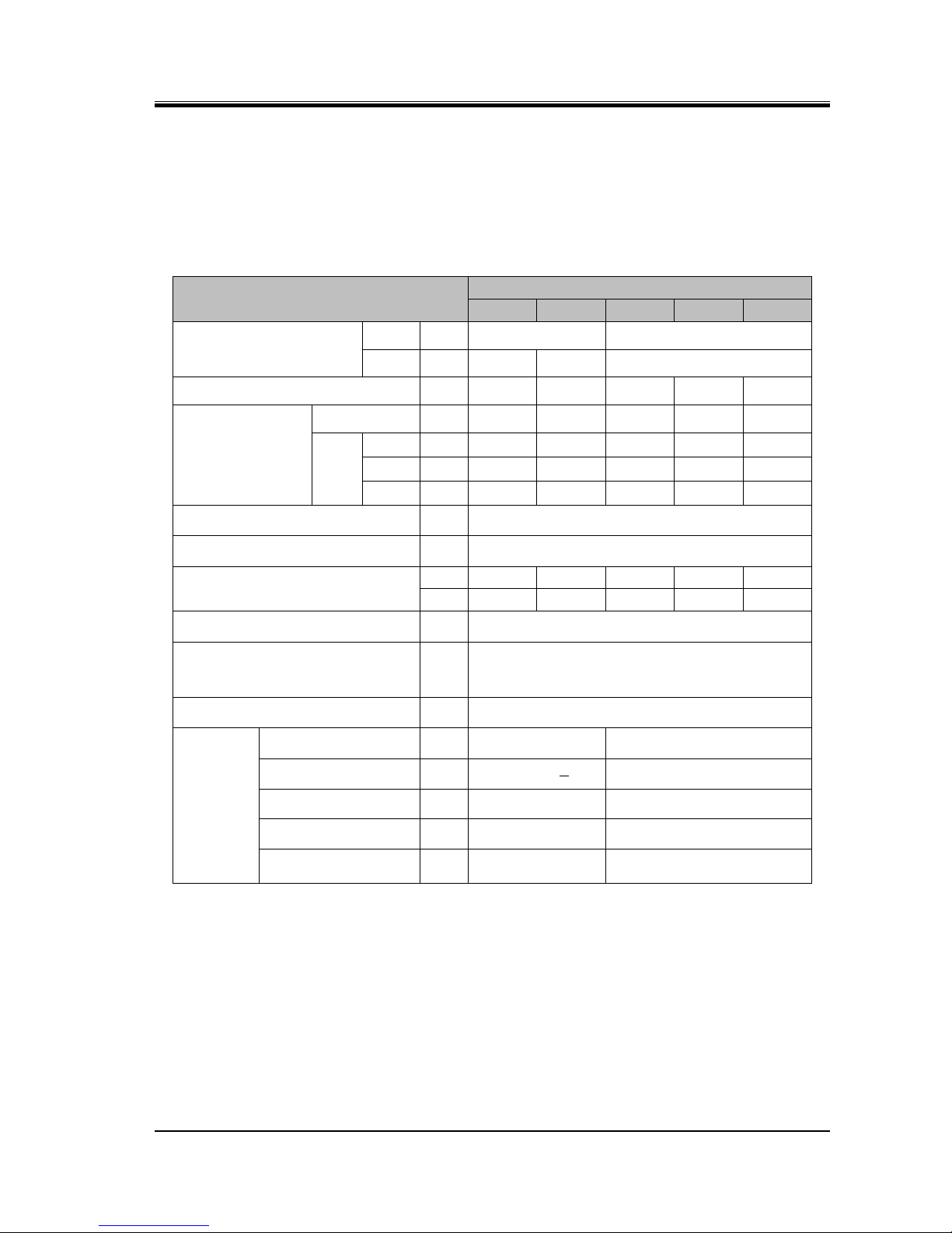
2.3.1 Standard Specifications
Table 2-1 Specifications of i-series Compressor
Items
Model
i125S
i125L
i160S
i160M
i160L
Flange motor connection
NEMA — 3**C, 40*C 3**D, 4**D
IEC — FF400 FF500 FF500 / FF600
Product mass (Compressor only)
kg
330 350 520 560 600
Mass of
compressor with
motor spacer
for NEMA
kg
490 510 670 710 750
for
IEC
FF400
kg
440 — — — —
FF500
kg — 480
630
670
710
FF600
kg — —
660
700
740
Standard speed 50Hz/60Hz min-1 2950/3550
Rotation direction — Clockwise as viewed from motor
Swept volume 50Hz/60Hz
m3/h
197/237
296/356
415/499
519/624
622/749
CFM 116/139 174/210 244/294 305/367 366/441
Refrigerant
—
R717 / R404A / R507A / R134a
Design pressure *Note MPa
2.6
(Applies to i-series compressors manufactured
and shipped in May 2014 or after.)
Capacity control — 3-step (100%, 75%, 50%) unloader
Connected
pipe size
Suction flange —
MYCOM 100A (4")
ANSI #300 5"
Discharge flange
—
MYCOM 65ACD ANSI #300 3"
Oil inlet port
— Rc1/2 MYCOM 65A
Economizer — Rc3/8 Rc3/4
Aquamizer
(Liquid injection)
— Rc1/4 Rc1/2
Unless otherwise noted, the pressure unit MPa represents the gauge pressure in this manual.
For limits of working temperature and pressure, see Section 2.3.2 "Operation Limits" in this
Chapter.
*Note: The design pressure varies according to each area, laws and ordinances of the country.
The design pressure of this list is the maximum value of the compressor. Therefore, the
real design pressure may become less than this value according to the law.
Please confirm real pressure on a name plate and individual specifications.
2203M4-JE-MY-iS2-N_2017.04.
Chapter 2 Compressor Specifications and Configuration
Screw Compressor i-series 2.3 Compressor Specifications
2-3
2.3.2 Operation Limits
Table 2-2 Operation Limits of i-series Compressor
Item
Normal operation range
*Note 1
Permissible limit
Speed
min-1
2950 @50 Hz
3550 @60 Hz
125S, 160S: Max. 4500 *Note 2
125L, 160M, 160L : Max. 3550
Discharge pressure
MPa
1.0 to 1.9 Max. 1.9
Suction pressure
MPa
0.02 to 0.35
Max. 0.6
Min. -0.05
Differential pressure for
lubrication (Po - Ps)
*Note3
MPa
≥ 0.5 Min. 0.5 *Note 4
Discharge gas temperature
°C
Condensing temperature +
15 to 90
Max. 90
Superheating degree of
suction gas
°C
5 to 20 —
Oil supply temperature
°C
30 to 60
Max. 80 BBSE
*Note 2
Min. 30
Supply oil viscosity
(kinematic viscosity)
mm2/s
13 to 40
Min. 13
Max. 300 (At start-up time)
Vibrat ion standar d value at
shipment
μm
(Half amplitude) 20 —
Noise standard value at
shipment
dB (A)
125S, L, 160S, M: 84
160L: 85
—
Unless otherwise noted, the pressure unit MPa represents the gauge pressure in this manual.
*Note 1: For operations outside the normal operation ranges, consult our compressor manufacturing
division.
*Note 2: When performing a speed-increasing operation by inverter at 70 °C or a bove oil temperature,
contact our compressor manufacturing division to confirm the temperature on the mechanical
seal sliding surface.
*Note 3: Po = Oil supply pressure, Ps = Suction pressure
*Note 4: This value excludes the start-up of the compressor. Refer to Note 2 in the next section.
Repeated startup and stop in a short period is harmful not for the startup devices and
electric machinery but also for the compressor itself. For information on the start/stop
limitations, refer to each instruction manual.
Wait at least 15 mi nutes after sto pping the compressor before restarting i t .
2203M4-JE-MY-iS2-N_2017.04.
Chapter 2 Compressor Specifications and Configuration
Screw Compressor i-series 2.3 Compressor Specifications
2-4
2.3.3 Alarm Set Values
To protect the compressor, please set the alarm shown in the table below.
Table 2-3 Application Limits of i-series Compressor *
Note 1
Item
Unit Alarm
Stop
Rotation speed min-1
High
—
i125S, i160S: 4550 (0 sec.)
i125L, i160M, i160L: 3650 (0 sec.)
Low — 1450 (0 sec.)
Discharge pressure MPa
High
1.9 (0 sec.)
2.0 (0 sec.)
Low — —
Suction pressure MPa
High
0.6 (30 sec.)
0.6 (60 sec.)
Low -0.05 (30 sec.) -0.05 (60 sec.)
Differential pressure for
lubrication
(Po - Ps) *Note 2
MPa
High — —
Low 0.6 (30 sec.) 0.5 (30 sec.) *Note 3
Discharge temperature °C
High
90 (5 sec.)
95 (0 sec.)
Low — —
Suction temperature °C
High
60 (60 sec.)
—
Low -58 (30 sec.) -60 (30 sec.)
Discharge superheat °C
High — —
Low 15 (60 sec.) 10 (60 sec.)
Suction superheat °C
High —
—
Low 0 (30 sec.) 0 (60 sec.)
Lubrication temperature °C
High
80 (60 sec.)
85 (60 sec.)
Low 30 (60 sec.) 25 (60 sec.)
Unless otherwise noted, the pressure unit MPa represents the gauge pressure in this manual.
*Note 1: The values in the parentheses are the maximum operation delay times.
The values have been set to protect the compressor.
*Note 2: Po = Oil supply pressure, Ps = Suction pressure
*Note 3: This alarm stop is set for normal operation. At the time of the start-up of the compressor,
it is not necessary to perform this alarm monitoring after start until 300 seconds.
2203M4-JE-MY-iS2-N_2017.04.
Chapter 2 Compressor Specifications and Configuration
Screw Compressor i-series 2.3 Compressor Specifications
2-5
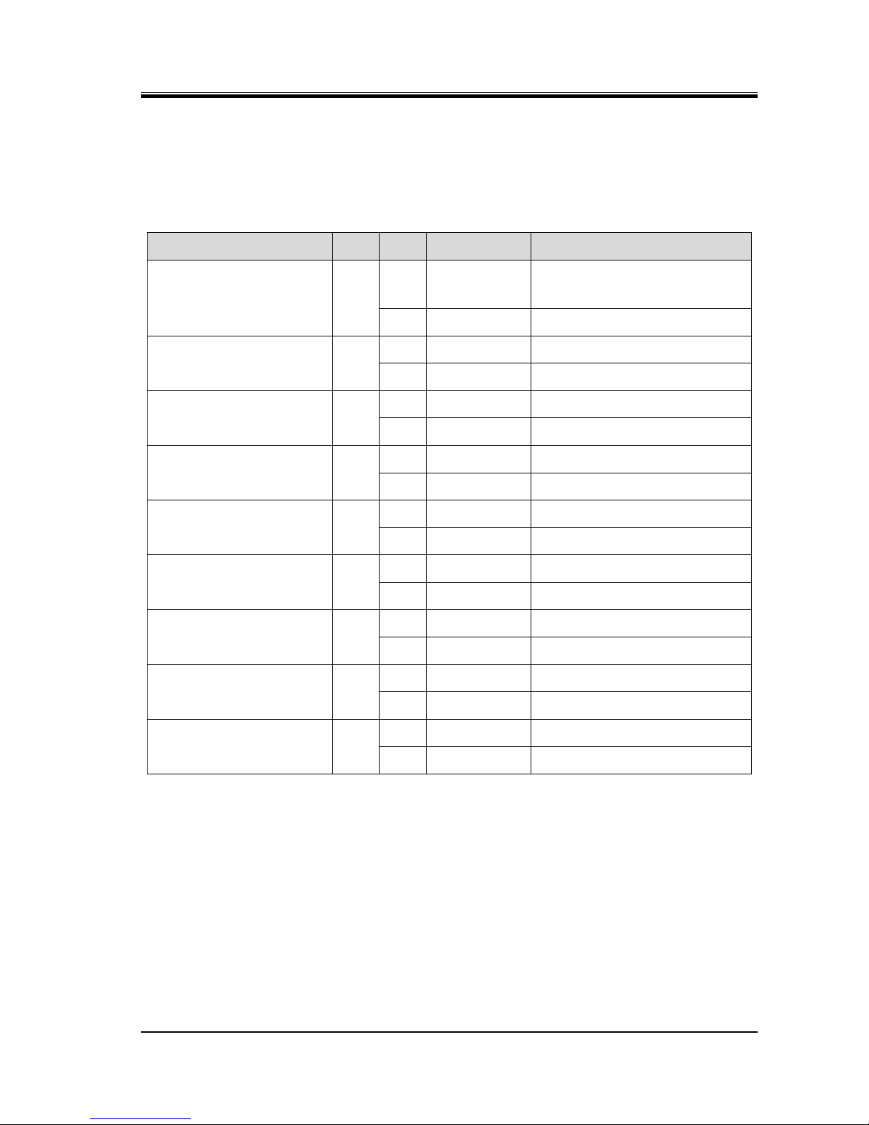
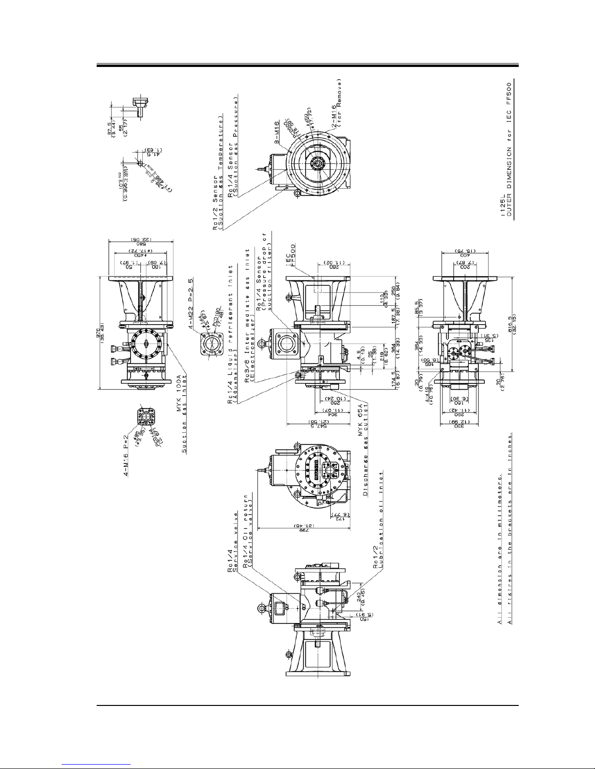
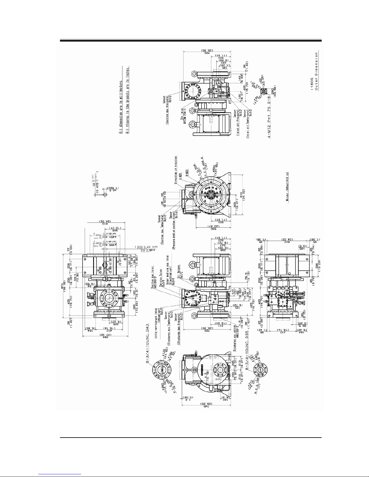
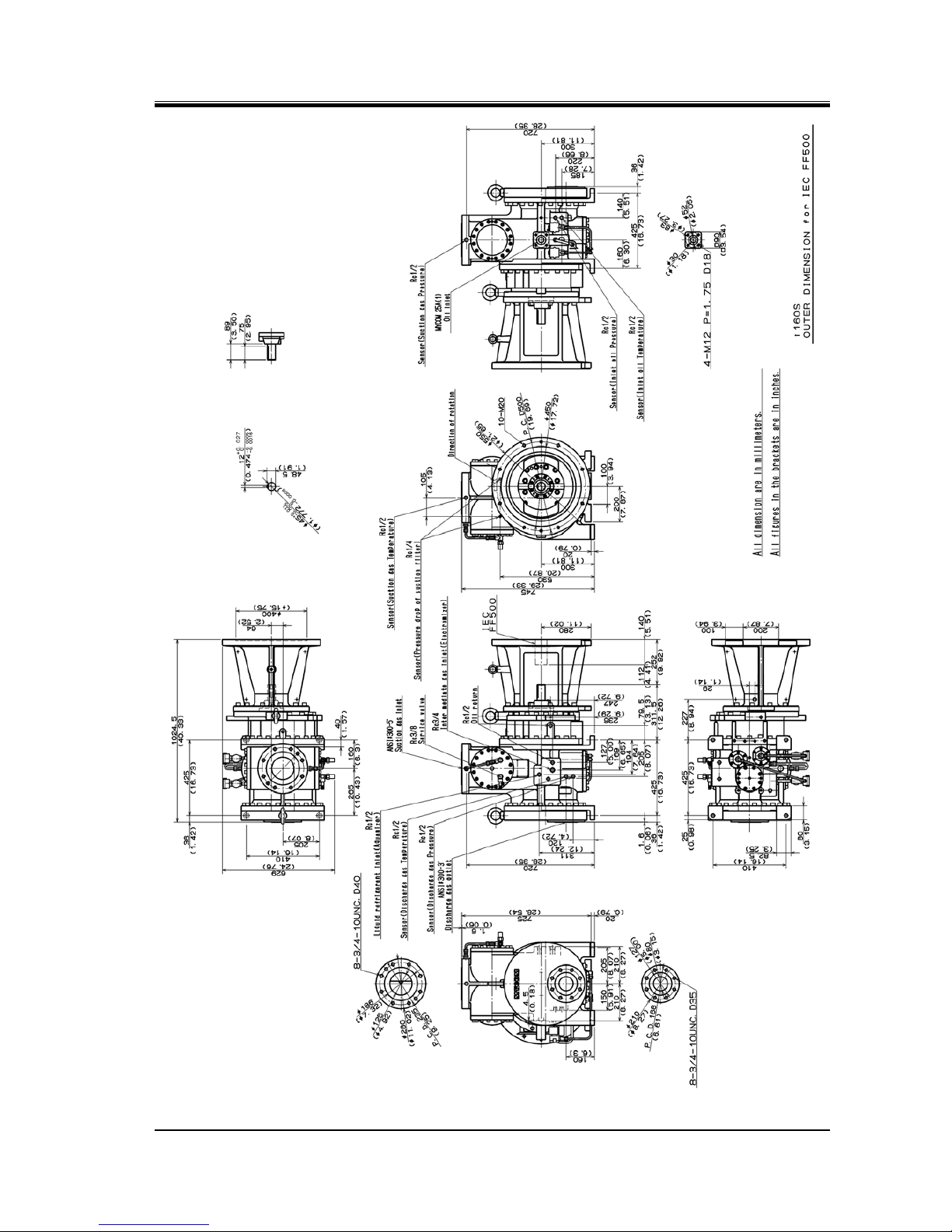
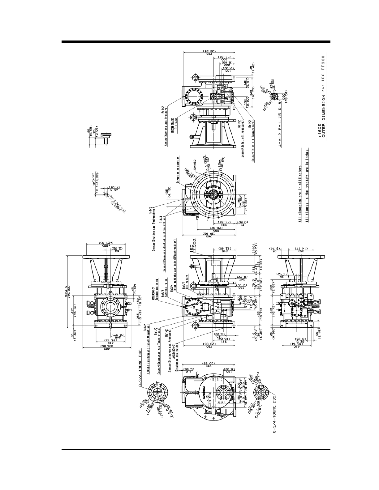
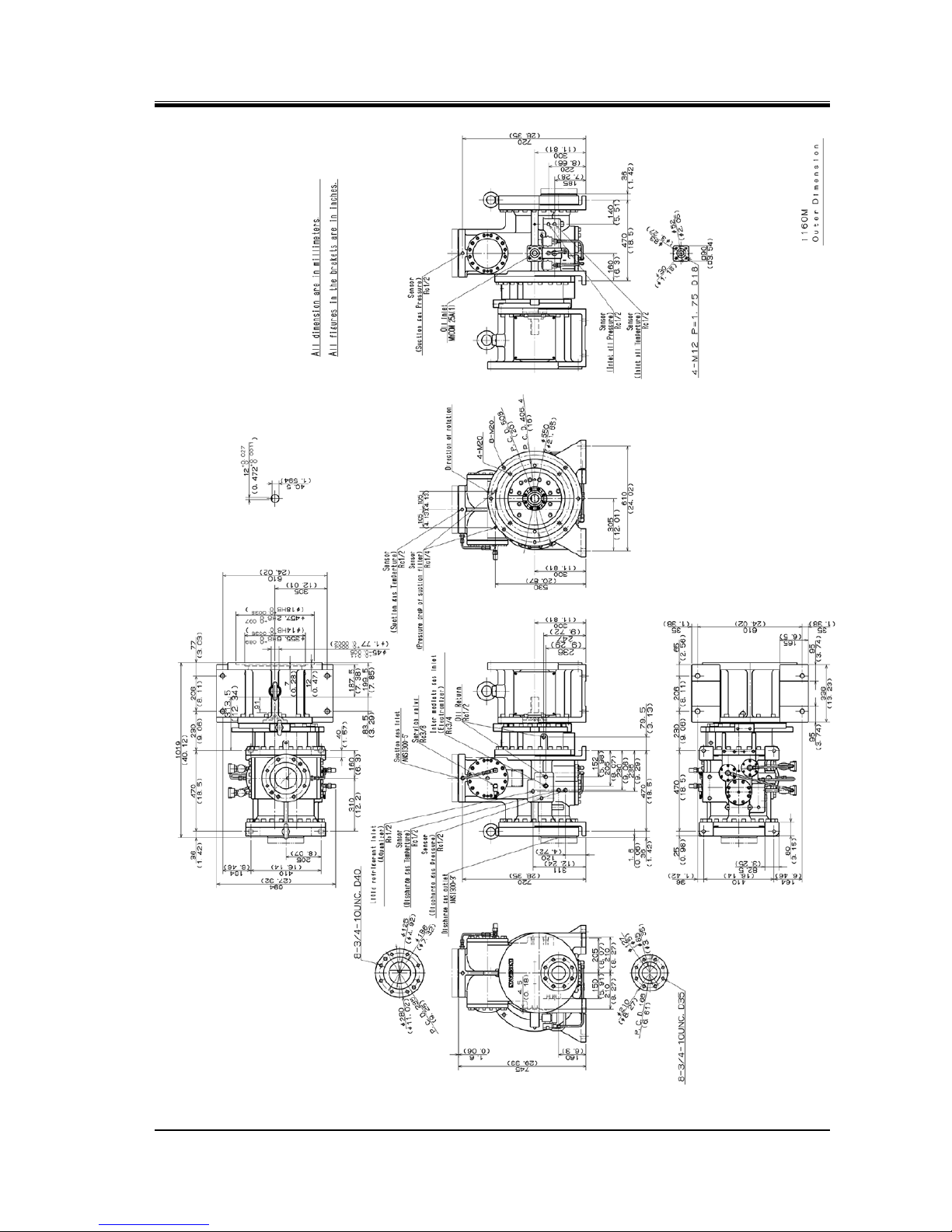
2.3.4 Outer Dimensions
Figure
2-1 i125S Outer Dimensions with a Spacer for Flange Motor (NEMA)
2203M4-JE-MY-iS2-N_2017.04.
Chapter 2 Compressor Specifications and Configuration
Screw Compressor i-series 2.3 Compressor Specifications
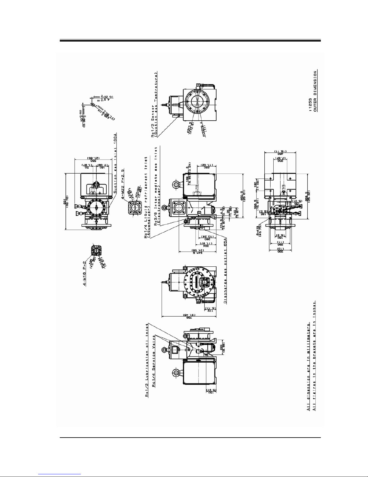
2-6
Figure
2-2 i125S Outer Dimensions with a Spacer for Flange Motor (IEC FF400)
2203M4-JE-MY-iS2-N_2017.04.
Chapter 2 Compressor Specifications and Configuration
Screw Compressor i-series 2.3 Compressor Specifications
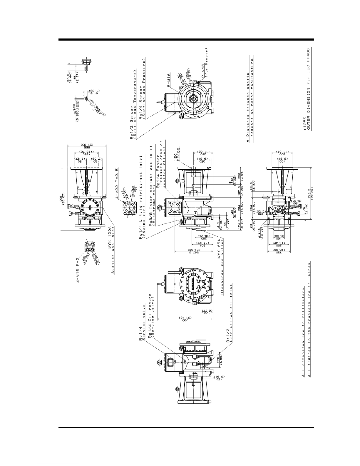
2-7
Figure
2-3 i125L Outer Dimensions with a Spacer for Flange Motor (NEMA)
2203M4-JE-MY-iS2-N_2017.04.
Chapter 2 Compressor Specifications and Configuration
Screw Compressor i-series 2.3 Compressor Specifications
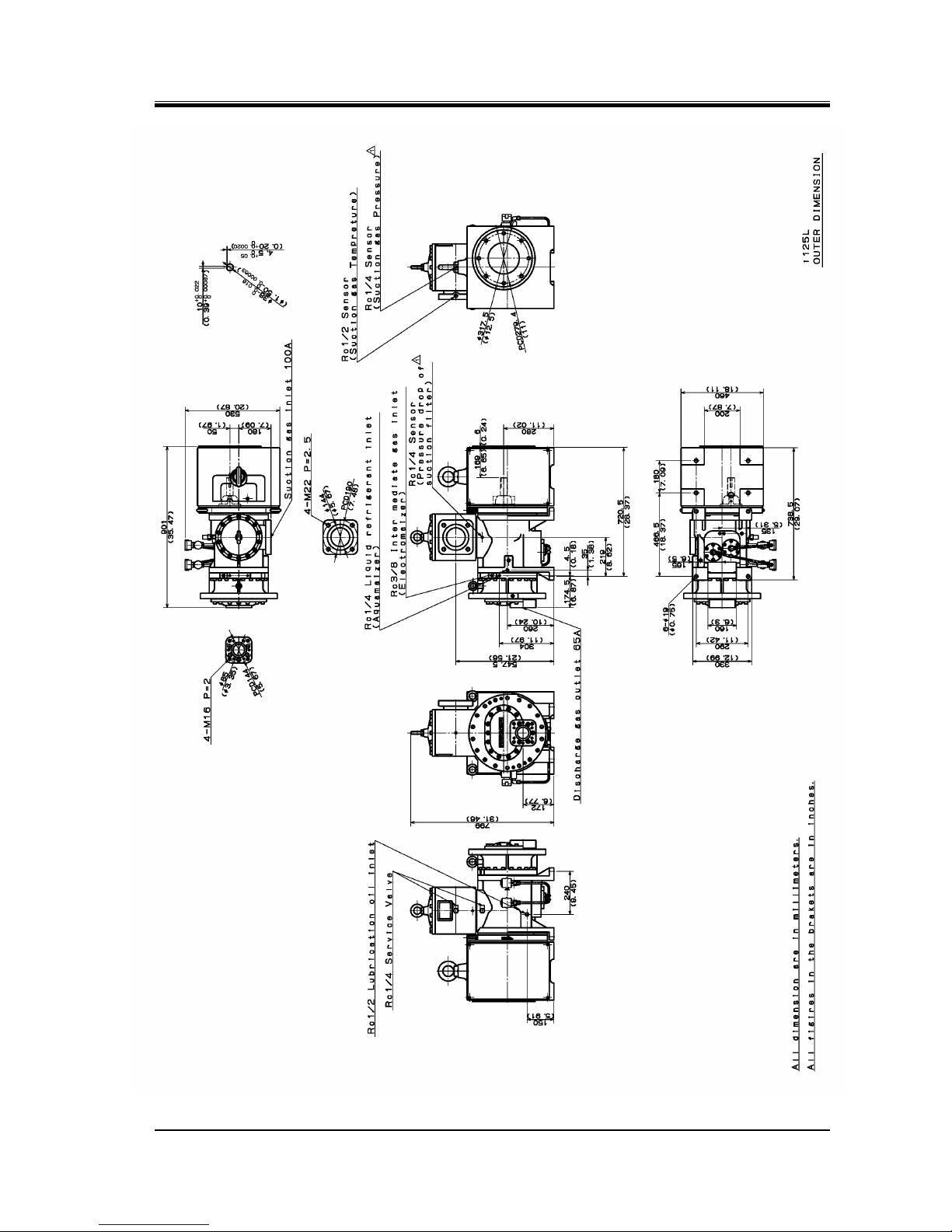
2-8
Figure
2-4 i125L Outer Dimensions with a Spacer for Flange Motor (IEC FF500)
2203M4-JE-MY-iS2-N_2017.04.
Chapter 2 Compressor Specifications and Configuration
Screw Compressor i-series 2.3 Compressor Specifications
2-9
Figure
2-5 i160S Outer Dimensions with a Spacer for Flange Motor (NEMA)
2203M4-JE-MY-iS2-N_2017.04.
Chapter 2 Compressor Specifications and Configuration
Screw Compressor i-series 2.3 Compressor Specifications
2-10
Figure
2-6 i160S Outer Dimensions with a Spacer for Motor Flange (IEC FF500)
2203M4-JE-MY-iS2-N_2017.04.
Chapter 2 Compressor Specifications and Configuration
Screw Compressor i-series 2.3 Compressor Specifications
2-11
Figure
2-7 i160S Outer Dimensions with a Spacer for Flange Motor (IEC FF600)
2203M4-JE-MY-iS2-N_2017.04.
Chapter 2 Compressor Specifications and Configuration
Screw Compressor i-series 2.3 Compressor Specifications
2-12
Figure
2-8 i160M Outer Dimensions with a Spacer for Flange Motor (NEMA)

2203M4-JE-MY-iS2-N_2017.04.
Chapter 2 Compressor Specifications and Configuration
Screw Compressor i-series 2.3 Compressor Specifications
2-13
Figure
2-9 i160M Outer Dimensions with a Spacer for Motor Flange (IEC FF500)

2203M4-JE-MY-iS2-N_2017.04.
Chapter 2 Compressor Specifications and Configuration
Screw Compressor i-series 2.3 Compressor Specifications
2-14
Figure
2-10 i160M Outer Dimensions with a Spacer for Flange Motor (IEC FF600)

2203M4-JE-MY-iS2-N_2017.04.
Chapter 2 Compressor Specifications and Configuration
Screw Compressor i-series 2.3 Compressor Specifications
2-15
Figure
2-11 i160L Outer Dimensions with a Spacer for Flange Motor (NEMA)

2203M4-JE-MY-iS2-N_2017.04.
Chapter 2 Compressor Specifications and Configuration
Screw Compressor i-series 2.3 Compressor Specifications
2-16
Figure
2-12 i160L Outer Dimensions with a Spacer for Flange Motor (IEC FF500)

2203M4-JE-MY-iS2-N_2017.04.
Chapter 2 Compressor Specifications and Configuration
Screw Compressor i-series 2.3 Compressor Specifications
2-17
Figure
2-13 i160L Outer Dimensions with a Spacer for Flange Motor (IEC FF600)

2203M4-JE-MY-iS2-N_2017.04.
Chapter 2 Compressor Specifications and Configuration
Screw Compressor i-series 2.4 Configuration of Compressor
2-18
2.4 Configuration of Compressor
2.4.1 Sectional Views
Figure
2-14 i125L Longitudinal Sectional View

2203M4-JE-MY-iS2-N_2017.04.
Chapter 2 Compressor Specifications and Configuration
Screw Compressor i-series 2.4 Configuration of Compressor
2-19
Figure
2-15 i125L Cross-Sectional View

2203M4-JE-MY-iS2-N_2017.04.
Chapter 2 Compressor Specifications and Configuration
Screw Compressor i-series 2.4 Configuration of Compressor
2-20
Figure 2-16
i125* Longitudinal Sectional View of Suction/Capacity Control Section

2203M4-JE-MY-iS2-N_2017.04.
Chapter 2 Compressor Specifications and Configuration
Screw Compressor i-series 2.4 Configuration of Compressor
2-21
Figure
2-17 i160S Longitudinal Sectional View

2203M4-JE-MY-iS2-N_2017.04.
Chapter 2 Compressor Specifications and Configuration
Screw Compressor i-series 2.4 Configuration of Compressor
2-22
Figure
2-18 i160S Cross-Sectional View

2203M4-JE-MY-iS2-N_2017.04.
Chapter 2 Compressor Specifications and Configuration
Screw Compressor i-series 2.4 Configuration of Compressor
2-23
Figure 2-19
i160* Longitudinal Sectional View of Suction/Capacity Control Section

2203M4-JE-MY-iS2-N_2017.04.
Chapter 2 Compressor Specifications and Configuration
Screw Compressor i-series 2.4 Configuration of Compressor
2-24
2.4.2 Exploded Views
Figure 2-20
Exploded View of i125S/L Parts with Motor Spacer

2203M4-JE-MY-iS2-N_2017.04.
Chapter 2 Compressor Specifications and Configuration
Screw Compressor i-series 2.4 Configuration of Compressor
2-25
Figure 2-21
Exploded View of i160S/L Parts with Motor Spacer

2203M4-JE-MY-iS2-N_2017.04.
Chapter 2 Compressor Specifications and Configuration
Screw Compressor i-series 2.4 Configuration of Compressor
2-26
2.4.3 Parts Configuration Table
Table 2-4 i125S/L Parts Configuration Table
P/N Part name Code No. Remarks Qty
1
Main Rotor Casing
-
i125S-* port
S:1
1
Main Rotor Casing
-
i125L-* port
L:1
2-1 Hexagon Socket Head Cap Screw NB35412-050 M12×50 SCM435 45
2-2
Hexagon Socket Head Cap Screw
NB35412-035
M12×35 SCM435
39
3
Alignment Pin NE242A13-050A
Φ13×50 with internal thread
and slot
4
3
Alignment Pin NE242A13-050A
Φ13×50 with internal
thread and slot for Motor
Spacer
2
4-1
Eye Bolt
NB600-16
M16 3 4-2
Eye Bolt
NB600-20
M20 1 4-3
Eye Bolt
NB600-30
M30 1 5-1
Suction Adapter -
i125
1
5-2
Strainer Cover
CS00510-I125
i125 1 6-1
Gasket, Suction Adapter
CS00600-I125
i125 t=0.5
1
6-2
Gasket, Strainer Cover
CS00900-I125
i125 t=0.5
1 7 O-ring
PA12-140
JIS B 2401 G140
1
10-1
Hexagon Socket Head Cap Plug
NF06-004
R1/8 S45C
5
10-2
Hexagon Socket Head Cap Plug
NF06-008
R1/4 S45C
10
10-3
Hexagon Socket Head Cap Plug
NF06-010
R3/8 S45C
S:6 L:5
10-4
Hexagon Socket Head Cap Plug
NF06-015
R1/2 S45C
1
11
Bearing Head
CS01100-I125
i125 1 12
Gasket, Bearing Head
CS01200-I125
i125 t=0.5
1
16
Bearing Cover -
i125 1 17
Gasket, Bearing Cover
CS01700-I125
i125 t=0.5
1
18-1
Hexagon Socket Head Cap Screw
NB35416-055
M16×55 SCM435
7
20
Spring Pin
NE3203-008
Φ3×8
1
22
End Cover
CS02200-I125
i125 1 23
Gasket, End Cover
CS02300-I125
i125 t=1.0
1
25
Male Rotor -
i125SM/SF FCD S:1set
26
Female Rotor
-
25
Male Rotor
CS02500-I125L
(M,F ASSY)
i125LM/LF FCD L:1set
26
Female Rotor
27-1
Radial Bearing
CS02800-FM125M
NU2308ET7
2
27-2
Radial Bearing
CS02800-FM125F
NU2309ET7
2
29-1
Snap Ring
NG11-090
H90 C type-Internal
1
29-2
Snap Ring
NG11-100
H100 C type-Internal
1
29-3
Snap Ring
NG12-040
S40 C type-External
1
30
Balance Piston
CS03000-I125
i125
1
31
Slotted Set Screw
NA14708-016
FM160 (M8×16)
1
32
Snap Ring
NG12-045
S45 C type-External
1

2203M4-JE-MY-iS2-N_2017.04.
Chapter 2 Compressor Specifications and Configuration
Screw Compressor i-series 2.4 Configuration of Compressor
2-27
P/N Part name Code No. Remarks Qty
33
Sleeve, Balance Piston
CS03300-I125
i125
1
34
Spring pin
NE3206-015
FM160 (Φ6×15)
1
35
O-ring
PA11-016
JIS B 2401 P16
1
38-1
Thrust Bearing M
CS03800-I125MP
Shared with i125M,FM11S
1
38-2
Thrust Bearing F
CS03800-125FP
Shared with i125F,125
1
39-1
Lock Nut
NG31-008
AN8 1 39-2
Lock Nut
NG31-009
AN9
1
40-1
Lock Washer
NG32-008
AW8 1 40-2
Lock Washer
NG32-009
AW9 1 41-1
Spacer, Thrust Bearing Outer Race M
CS25000-FM11S
FM11S Thrust Washer
1
41-2
Spacer, Thrust Bearing Outer Race F
CS04100-I125F
i125F
1
42-1
Spacer, Thrust Bearing Alignment M
CS04200-I125M
i125M
1
42-2
Spacer, Thrust Bearing Alignment F
CS04200-125
125***
1
43-1
Thrust Bearing Gland M
CS04300-I125M
i125M
1
43-2
Thrust Bearing Gland F
CS04300-I125F
i125F 1 45
Hexagon Head Bolt
NB111008-035
M8X35-10.9 SCM435
8
46
Spring Was her
ND320-008
M8
8
48
Retainer, Oil Seal
CS04800-125
125*** 1 49
O-ring
PA12-085
JIS B 2401 G85
1
50
Oil Seal
CS05000-125D
125*** Rareflon
1
51 Seal Cover CS05100-125BBS
Shared with 125*** seal pot
specifications
1
52
Gasket, Seal Cover
CS05200-125N
125*** 1 53
Hexagon Socket Head Cap Screw
NB35406-020
M6×20 SCM435
8
58
Hexagon Socket Head Cap Screw
NB35408-030
M8X30 SCM435
12
91
Coupling Key
CS09100-125
125L** 1 92
Suction Flange with hole
CS74000-100
MYK 100A (Male)
1
92
Suction Cover Flange
CS71400-P100
MYK 100A(Male)
1
93
Gasket, Suction Flange
CR72000-100N
MYK 100A
1
94
Hexagon Head Bolt, Suction Flange
NB12022-060
M22×60 SCM435
S:4 L:8
95
Discharge Flange with hole
CS71400-065CDMK
MYK 65CD (Male)
1
235
Discharge Flange Spacer
FX101-125
65CD for 125
1
236
Gasket, Suction Flange Spacer
CS23600-125N
65CD for 125
1
96
Gasket, Discharge Flange
CS23600-125N
MYK 65CD
1
97
Hexagon Head Bolt, Discharge Flange
NB12016-045
M16×45 SCM435
S:4 L:8
100
Mechanical Seal Assembly
CS10002-125EBS
BBSE 125***
1set
235-1
Motor Spacer
-
for NEMA Motor Flange
1
CS23500-I125IEC40
for IEC FF400
CS23500-I125IEC50
for IEC FF500
235-2
Plate, Motor Spacer
CS23510-I125
i125
2
-
for IEC FF400 (1), (2)
2
-
for IEC FF500 (1), (2)
2
235-3
Hexagon Socket Head Cap Screw
NB35406-010
M6×10 SCM435
8
237-1
Torsional Slip Washer M
CS23700-FM125M
FM125 M
1

2203M4-JE-MY-iS2-N_2017.04.
Chapter 2 Compressor Specifications and Configuration
Screw Compressor i-series 2.4 Configuration of Compressor
2-28
P/N Part name Code No. Remarks Qty
237-2
Torsional Slip Washer F
CS23700-125
125L**
1
250-1
Thrust Washer M CS04200-I125M
i125M Spacer, thrust
bearing alignment
1
250-2
Thrust Washer F
CS25000-125
125***
1
391 Unloader Piston CS39100-I160 i160* 2
392
Spring
CS39200-F125
FM125
2
393
Unloader Cover
CS39300-I160
i160* 2 395
Gasket, Unloader Cover
CS39500-I160
i160*
2
480
Strainer Element
CS48000-I160
i160* 1 481
Retainer, Strainer Element
CS48100-I125
i125
1
482
Hexagon Socket Head Cap Screw
NB35406-015
M6×15 SCM3
2
485
Check Valve Spring
CS48500-F125
FM125
1
486
Hexagon Nut
NC622-10
U-NUT M10
1
487
Plain Washer ND193-10
JISB1256 small-sized,
round-shaped 10-22H
1
488-1
Seat Stopper (1)
CS48800-F125
FM125
1
488-2
Seat Stopper (2)
CS48800-F1252
FM125
1
489
Valve Seat
CS48900-I125
i125 1 490
Valve Plate
CS49000-I125
i125
1
491
Check Valve Shaft
CS49100-I125
i125 1 495
O-ring
PA11-007
JIS B 2401 P7
1
533 Solenoid Valve
KF711-XOF1
SPOLAN XOF-120V
2
KF711-XOF2
SPOLAN XOF-240V
534
Nipple (High Pressure)
NN410-080
R3/8 Sch40 80L
2
535
Connection (L-type)
NJ3-0803NE
L-Φ8-R3/8 JO4060
2
536
Connection (L-type)
NJ3-0802KNNT
L-Φ8-R1/4 JO4050
2
538
Piping
QA11-08
Φ8 STS
2
546
Wave Washer
ND91-016
FM125 BW16
1
555
Angle Valve
NF042-0302N
R1/4×Rc1/4
2
795
Cover Plate, Discharge Flange
CS71500-I1251
i125 4.5x84D
1
795
Cover Plate, Suction Flange
CS71500-I1252
i125 4.5x123D
1
The part code of the O-ring is the one assigned to NBR-70-1 which is standard
material. When the material of the O-ring is other than NBR, a different part code is
used for each material.
If you are using O-rings made from other than the standard material, please
contact MAYEKAWA when pl acing an order.

2203M4-JE-MY-iS2-N_2017.04.
Chapter 2 Compressor Specifications and Configuration
Screw Compressor i-series 2.4 Configuration of Compressor
2-29
Table 2-5 i160* Parts Configuration Table
P/N
Part name Code No. Remarks
Qty
1
Main Rotor Casing
-
i160S-* port (L, M, H)
S:1
1
Main Rotor Casing
-
i160M-* port (L, M, H)
M:1
1
Main Rotor Casing
-
i160L-* port (L, M, H)
L:1
2
Hexagon Socket Head Cap Screw
NB35416-055
M16×55 SCM435
71
3 Alignment Pin NE242A13-050A
13×50L With internal thread
and slot
4
3 Alignment Pin NE242A13-050A
13×50L With internal thread
and slot for Motor Spacer
2
4-1
Eye Bolt
NB600-12
M12 3 4-2
Eye Bolt
NB600-24
M24 1 4-3
Eye Bolt
NB600-24
M24 1 5
Strainer Cover
CS00500-I160
i160
1
6
Gasket, Strainer Cover
CS00900-I160
i160 t=0.5
2
7-1
O-ring
PA12-150
JIS B 2401 G150
1
7-2
O-ring
PA12-140
JIS B 2401 G140
1
8
Check Valve Cover
CS00800-I160
i160 1 10-1
Hexagon Socket Head Cap Plug
NF06-004
R1/8 S45C
5
10-2
Hexagon Socket Head Cap Plug
NF06-008
R1/4 S45C
9
10-3 Hexagon Socket Head Cap Plug NF06-010 R3/8 S45C
S,L:3
M:4
10-4 Hexagon Socket Head Cap Plug NF06-015 R1/2 S45C
S, L:15
M:14
10-5
Hexagon Socket Head Cap Plug
NF06-020
R3/4 S45C
1
10-6
Hexagon Socket Head Cap Plug
NF06-025
R1 S25C
2
11
Bearing Head
CS01100-I160
i160 1 12
Gasket, Bearing Head
CS01200-I160
i160 t=0.5
1
16
Bearing Cover
CS01600-I160
i160 1 17
Gasket, Bearing Cover
CS01700-I160
i160 t=0.5
1
18-1
Hexagon Socket Head Cap Screw
NB35412-040
M12×40 SCM435
40
20
Spring Pin
NE3203-010
3×10L
1
22
End Cover
CS02200-I160N
i160 1 23
Gasket, End Cover
CS02300-I160N
i160 t=1.0
1
25 Male Rotor
-
i160SM/SF FCD S:1set
26 Female Rotor -
25
Male Rotor
-
i160MM/MF FCD M:1set
26 Female Rotor
-
25 Male Rotor -
i160LM/LF FCD L:1set
26
Female Rotor
-
27-1
Radial Bearing M
CS02800-FM160M
NU2311ET7
2
27-2
Radial Bearing F
CS02800-FM160FCT
NU2312ET7
2
29-1
Snap Ring
NG11-120
H120 C type-Internal
1
29-2
Snap Ring
NG11-130
H130 C-type-Internal
1
29-3
Snap Ring
NG12-060
S60 C type-External
1
30 Balance Piston CS03000-I160 i160 1

2203M4-JE-MY-iS2-N_2017.04.
Chapter 2 Compressor Specifications and Configuration
Screw Compressor i-series 2.4 Configuration of Compressor
2-30
P/N
Part name Code No. Remarks
Qty
30
Balance Piston (LT) CS03300-FM160LT
Special part for FM160
For H-port
1
31
Slotted Set Screw
NA14708-016
FM160 (M8×16)
1
32
Snap Ring
NG12-055
S55 C type-External
1
33
Sleeve, Balance Piston
CS03300-I160
i160
1
33 Sleeve, Balance Piston (LT)
CS03300-FM160LT
Special part for FM160
For H-port
1
34
Spring pin
NE3206-015
FM160 (6×15L)
1
35
O-ring
PA11-024
JIS B2401 P24
2
38-1
Thrust Bearing M
CS03800-FM160P
7311B Shared with FM160
1
38-2
Thrust Bearing F
CS03800-160P
7312B Shared with 160
1
39-1
Lock Nut
NG31-011
AN11
1
39-2
Lock Nut
NG31-012
AN12
1
40-1
Lock Washer
NG32-011
AW11
1
40-2
Lock Washer
NG32-012
AW12
1
41-1
Spacer, Thrust Bearing Outer Race M
CS04100-I160M
i160 M
1
41-2
Spacer, Thrust Bearing Outer Race F
CS04100-I160F
i160 F
1
42-1
Spacer, Thrust Bearing Alignment M
CS04200-I160M
i160 M
1
42-2
Spacer, Thrust Bearing Alignment F
CS04200-I160F
i160 F
1
43-1
Thrust Bearing Gland M
CS04300-I160M
i160 M
1
43-2
Thrust Bearing Gland F
CS04300-I160F
i160 F 1 45
Hexagon Socket Head Cap Screw
NB35410-050
M10×50 SCM435
8
46-1 Conical S pri ng Was her ND150-10
8
46-2 Plain Washer
ND193-10
JIS B 1256 Small-sized,
round-type 10-22H
8
48
Retainer, Oil Seal
CS04800-160
160***
1
49
O-ring
PA12-090
JIS B 2401 G90
1
50
Oil Seal Rareflon
CS05000-160VD
160*** (S55×70×9)
1
51
Seal cover
CS05100-160
160***
1
52
Gasket, Seal Cover
CS05200-160N
160*** t=0.5
1
58
Hexagon Socket Head Cap Screw
NB35408-030
M8×30 SCM435
8
91
Coupling Key
CS09100-160
160*** single round12×8×75
1
92
Suction Flange with hole
NX2381-125MK
ANSI #300 5"
1
92
Suction Cover Flange
CZA01-300C05B
ANSI #300 5"
1
93
Gasket, Suction Flange
PL300-125
ANSI #300 5"
1
94-1
Stud Bolt (Suction Side)
NBU703/4-103
3/4-10UNC 103L
8
94-2
Hex Nut (Suction / Discharge)
NCU1503/4-10UNC
3/4-10UNC
8
95
Discharge Flange with hole
NX2381-080MK
ANSI #300 3"
1
95
Discharge Cover Flange
CZA01-300C03B
ANSI #300 3"
1
96
Gasket, Discharge Flange
PL300-080
ANSI #300 3"
1
97
Stud Bolt (Discharge Side)
NBU603/4-10UNC
3/4-10UNC
8
100
Mechanical Seal Assembly
CS10002-160EBS
160V BBSE
1set
150-1
O-ring, Thrust Bearing Gland M
PA12-110
JIS B 2401 G110
1
150-2
O-ring, Thrust Bearing Gland F
PA12-115
JIS B 2401 G115
1

2203M4-JE-MY-iS2-N_2017.04.
Chapter 2 Compressor Specifications and Configuration
Screw Compressor i-series 2.4 Configuration of Compressor
2-31
P/N
Part name Code No. Remarks
Qty
216-1
Flange with hole , Oil Inlet Port
CR74000-025
MYCOM 25A (Male)
1
216-2
Flange Gasket, Oil Inlet Port
CR72000-025N
MYCOM 25A
1
216-3
Hexagon Head Bolt
NB35412-035
M12×35 SCM435
4
216-4 Cover Plate (for Airtight/Pressure Test) CS71500-025
MYCOM 25A
Attached at shipment.
1
235-1 Motor Spacer
CS23500-I160N for NEMA Motor Flange
1
CS23500-I160IEC50
for IEC FF500
CS23500-I160IEC60
for IEC FF600
235-2 Plate, Motor Spacer
CS23510-FM160
NEMA Motor Flange Spacer
2
FF500 Motor Flange Spacer
FF600 Motor Flange Spacer
235-3
Hexagon Socket Head Cap Screw
NB35406-010
M6×10 SCM435
8
235-4
Hexagon Socket Head Cap Screw
NB35416-055
M16×55 SCM435
12
237-1
Torsional Slip Washer M
CS23700-FM160M
FM160
1
237-2
Torsional Slip Washer F
CS23700-160
160***
1
250-1
Thrust Washer M
CS25000-FM160M
FM160
1
250-2
Thrust Washer F
CS25000-160
160*** Thrust washer
1
391
Unloader Piston
CS39100-I160
i160 2 392
Spring
CS39200-F125
FM125
2
393
Unloader Cover
CS39300-I160
i160
2
395
Gasket, Unloader Cover
CS39500-I160
i160 t=1.0
2
-
Hexagon Socket Head Cap Screw
(common to No.58)
NB35408-030 M8×30 SCM435 12
480
Strainer Element
CS48000-I160
i160 #150 Φ160×200
1
481
Retainer, Strainer Element
CS48100-I160
i160
1
485
Check Valve Spring
CS48500-I160
i160 1 486
Hexagon Nut
NC622-10
FM160(U-NUT M10)
1
487
Plain Washer
ND193-10
Small-sized SPCC1 M10
1
488
Seat Stopper
CS48800-I160
i160 1 489
Valve Seat
CS48900-I160
i160 1 490
Valve Plate
CS49000-I160
i160
1
491
Check Valve Shaft
CS49100-I160
i160 1 495
O-ring
PA11-007
JIS B 2401 P7
1
533 Solenoid Valve
KF711-XOF1
SPORLAN XOF-120V
2
KF711-XOF2
SPORLAN XOF-240V
534
Nipple (High Pressure)
NN410-100
Rc3/8×100L Sch40
2
535
Connection (L-type)
NJ3-0803NE
L-Φ8-R3/8 JO4060
2
536
Connection (L-type)
NJ3-0802KNNT
L-Φ8-R1/4 JO4050
2
538
Piping
QA1802-08
Φ8 STS
2
550 Check Union KD122-12E I-Φ12-R3/8
L: 2
S, M: 1
551 Connection (I-type) NJ2-1203NE I-Φ12-R3/8 JO4570
L: 2
S, M: 1
552
Piping
QA1802-12
Φ12 STS
1

2203M4-JE-MY-iS2-N_2017.04.
Chapter 2 Compressor Specifications and Configuration
Screw Compressor i-series 2.4 Configuration of Compressor
2-32
P/N
Part name Code No. Remarks
Qty
553
Chuck Union
KD122-10E
I-Φ10-R1/4 KZC10-050E
1
554
Angle Valve
NF067-02
TC-1 R1/4×Rc1/4
1
555
Angle Valve
NF067-03
TC-1 R3/8×Rc1/4
1
556
Connection (I-type)
NJ2-1003NE
I-Φ10-R3/8
1
557
Piping
QA1802-10
Φ10 STS
1
558
Hexagon Bushing
NF031-0403
JO5007 R1/2×Rc3/8
1
559
Hose Nipple
NN5102-050
8A×50
1
795
Cover Plate, Discharge Flange
CS71500-I1601 i160 4.5x146D 1
794 Cover Plate, Suction Flange
CS71500-I1602 i160 4.5x213D 1
The part code of the O-ring is the one assigned to NBR-70-1 which is standard
material. When the material of the O-ring is other than NBR, a different part code is
used for each material.
If you are using O-rings made from other than the standard material, please
contact MAYEKAWA when pl acing an order.

2203M4-JE-MY-iS2-N_2017.04.
Chapter 2 Compressor Specifications and Configuration
Screw Compressor i-series 2.5 Mechanisms
2-33
2.5 Mechanisms
2.5.1 Basics of the Screw Compressor
The screw compressor is categorized as a positive displacement rotary compressor.
As shown in Figure 2-22, the ref rigerant (g as) is contin uousl y com press ed by the 3-dim ens ional space s
that are formed by a pair of male and female screw rotors (with different sectional profiles) and the
casing, as the spaces change continuously.
The rotor having 4 protr uding lobe profiles is called a male or M rotor, and the rotor having 6 c oncave
profiles is called a female or F rotor. In this manual, they are referred to as M rotor and F rotor.
The compressor is driven by the motor connected to the shaft of the M rotor.
Figure 2-22
Compressor Mechan ism
2.5.2 Suction Process
As shown in Figure 2-23, the rotors with different lobe profiles are engaged. As the rotors turn, the
volume between the M and F rotor lobe profiles and the com press or cas ing graduall y increas es starting
from the suction side.
As the rotation continues, at a certain point when the volume reaches its maximum, the rotors isolate the
gas (volume), which is enclosed by the rotors and the compressor casing, from the suction port and then
continues rotation.
Figure
2-23 Suction Process

2203M4-JE-MY-iS2-N_2017.04.
Chapter 2 Compressor Specifications and Configuration
Screw Compressor i-series 2.5 Mechanisms
2-34
2.5.3 Compression Process
As the rotors rotate further, the volume between t he rotor lobes decreases while t he sealing l ine moves
toward the discharge side, which compresses the trapped refrigerant gas.
2.5.4 Discharge Process
The volume between the r o tor lobes decreases t o a le ve l pre det er mined by the dischar ge p ort. With the
rotations of the rotors, the compressed refrigerant gas is pushed out to the discharge port.
2.5.5 About Volume Ratio (Vi)
Volume ratios (Vi) are indicated in property tables or
catalogs by using port symbols L, M and H.
The volume ratio represented by each symbol
( screw compressor) is as follows:
L=2.63, M=3.65, H=5.80.
Volume of suctioned refrigerant gas
immediately before the start of compression
Vi =
Volume of refrigerant gas just before pushed
out to discharge port
Decide which volume ratio (L, M or H ) should be used
according to operating conditions. If the compressor is
used with a volume ratio that does not match operating
conditions, operation will go inefficiently wasting the power.
The relationship between volume ratios and generally
used compression ratios is as follows:
(Vi)κ= πi = Pd/Ps κ = Cp/Cv of refrigerant gas
Vi = Design volume ratio πi = Design compression ratio
Vi is related to the specific heat ratio (κ) and therefore its value relative to the compression ratio varies
depending on the type of refrigerant gas.
Figure 2-24 Compression Process
Figure 2-25 Discharge Process
Figure 2-26 Volume Ratio

2203M4-JE-MY-iS2-N_2017.04.
Chapter 2 Compressor Specifications and Configuration
Screw Compressor i-series 2.5 Mechanisms
2-35
(A) Properly adapted Vi to load condition
Both the required compr es sion ratio and Vi are low. Both the required compression ratio and Vi are high.
(B) Improperly adapted Vi to load c on dition
Too low Vi compare d with necessary compr es sion ra t io. Too high Vi compared with necessary compr es sion ra tio
Figure 2-27 Relationship between Volume ratio (Vi) and Operation Conditions

2203M4-JE-MY-iS2-N_2017.04.
Chapter 2 Compressor Specifications and Configuration
Screw Compressor i-series 2.5 Mechanisms
2-36
2.5.6 Capacity Control Mechanism
The capacity control of i-series com pr essor can be co ntrol led in t hree steps of 50%, 75% and 100% via
the unloader piston installed at each male rotor side and female rotor side in the main rotor casing.
Each unloader piston controlled by solenoid valve.
Figure 2-28 Capacity Control Mechanism
Table 2-6 Control of Solenoid V alves for Capacity Control
A B
100% ON (Opened) ON (Opened)
75% OFF (Closed) ON (Closed)
50% OFF (Closed) OFF (Closed)
Standstill
(50%)
OFF (Closed) OFF (Closed)
No. Description
①
Female Rotor
②
Male Rotor
③
Unloader Piston
④
Piping
A
Solenoid Valve
B
Solenoid Valve

2203M4-JE-MY-iS2-N_2017.04.
Chapter 2 Compressor Specifications and Configuration
Screw Compressor i-series 2.5 Mechanisms
2-37
Solenoid Valve for Capacity Control
Table 2-7 Specifications of the Solenoid Valves
Item
Solenoid Valve
SX07-03GN
(Japan domestic)
SPORLAN XOF
(Foreign)
Coil ratings Volts
AC V
100, 200
120, 208 to 240
DC V — 24
Watts W 11/10
10
Cycles
Hz
50/60
50/60
Piping joint
—
Rc3/8
3/8 NPT Female
Port size
mm 3 2.8
Maximum Operating
pressure differential required
Mpa 2 1.7
Note: The pressure value represents the gauge pressure.
●
Solenoid valves for capacity control are indoor specifications. Make sure not to drop
dew condensation water onto the solenoid valves by installing appropriate thermal
protection on the s uction piping to t he compressor.

2203M4JE-MY-iS2-N_2017.04.
Chapter 3 Installation
Screw Compressor i-series 3.1 General Precautions for Installation
3-1
Chapter 3 Installation
3.1 General Precautions for Installation
The description in Chapter 3 “Installation” assumes that the compressor is installed to a package
unit intended for standard type refrigeration/cold storage.
If the package unit you are actually using is not the one for standard type refrigeration/cold
storage, prepare a proper installation m anual by referr ing to the desc ription in thi s chapter and
paying due consideration to safety, before installing the compressor.
If there are any questions, please contact one of our local sales offices or service centers.
In some cases, it may be required that install ation is performed b y qualified personnel. Mak e
sure that the work is performed by qualified personnel in compliance with local laws,
ordinances and other regulations/requirements.
Read this chapter and related documents, and fully understand their contents before
performing installation.
Electrical works should be performed only by electrical engineers.
3.2 Installation Works
3.2.1 Unpacking
Check that there are no abnormalities such as damage on the compressor.
If there are abnorm alities or deficient parts on t he compressor, please contact one of our local
sales offices or service centers immediately.
Unnecessary packing mater ials should be discarded according to th e laws and ordinances, or
your company's rules.
3.2.2 Storage
Perform the followings to store the compressor before installation.
Store it indoors.
Infuse nitrogen gas into the compressor and seal it. (Pressure: approximately 0.15 MPa)
3.2.3 Transportation
Dropping of the lifted compressor may cause death or serious injury to the worker.
Do not allow any one t o be under the lifted compres sor.
1. For lifting the compressor within the safety limit, use lifting equipment and tools appropriate for the
mass of the compressor.
2. Secure sufficient space for safe lifting.
3. Always chec k the wire ropes bef ore using them. T horoughly check the wire ropes for problem s
such as kinks, k nots and brok en s trands. D o no t perf orm lifting work bef ore c onfirm ing the s afet y
of the wire ropes. If you cannot make a correct evaluation or judgment, entrust an expert to check.

2203M4JE-MY-iS2-N_2017.04.
Chapter 3 Installation
Screw Compressor i-series 3.2 Installation Works
3-2
4. To lift the compressor, attach the wire ropes to the appended eye bolts by using appropriate
shackles and hooks. Use the eye bolts only for lifting the compressor.
Figure 3-1 Eye bolts for lifting the compressor (Arrows)
The compressor eye bolts must not be used for lifting the package unit. To lift the
package unit, use the lifting chains provided around the base or other lifting means
provided on the base.
5. Check path of compres sor installation to m ake sure it is free of o bstacles in cons ideration of the
compressor size.
6. Before lifting, check that the hook is located above the gravity center of the compressor.
7. Before starting to lift up the compressor, instruct all the work ers to be sufficiently awa y from the
lifting area.
8. Just before s tarting to lift up, provide the c owork ers with a sign (s uch as a call, hand s ignal, etc.)
of starting the lifting action. Do not start to lift up unl es s the sign ( suc h as a call, hand signal, etc.)
has been fully acknowledged.
9. Slowly reel up the wire ropes until immediately before the compressor leaves the ground.
10. Then, reel up the wire ropes a little further until the compressor is slightly up away from the ground.
Check that the com pressor is not ti lted. If the compr essor is tilted, retur n the com pressor to the
ground and correct the tilt by adjusting the wire ropes. After that, restart the lifting operation.
11. Be sure to lift up the compressor slowly. If it is lifted rapidly, it may damage the lifting tools such as
wire ropes or a part of the compressor.
12. When the lifting work s tarts, obser ve to see if wire rop es an d liftin g t ools are normal. Be sure that
the compressor is not tilted.
13. When moving the lifted compressor, always use guiding ropes.
14. When moving the compressor, turn away workers from the movement direction and check safety.
15. Do not lift the compressor above the safety passage unless absolutely necessary.
16. Do n ot lower the compressor on the s afety passage. Always keep the safet y passage free of
obstacles.
17. Rem ove an y obs tacles bef ore lo wering the c om pressor ont o th e groun d. T he co m pressor s hould
not be tilted or unstable.
18. Before lowering the compressor, announce to the workers around the working area in advance.
19. W hen lowering the compressor onto two or more blocks, align the tops of blocks so that the
compressor becomes stable horizontally on them.
20. Slowly lower the lifted compressor so that it is not damaged by shock.

2203M4JE-MY-iS2-N_2017.04.
Chapter 3 Installation
Screw Compressor i-series 3.2 Installation Works
3-3
3.2.4 Preparation for Installation
Installation Space
Secure sufficient working space for easy operation, cleaning, maintenance, and inspection.
Lighting
Provide sufficient lighting to allow easy operation, cleaning, maintenance, and inspection.
Ventilation
If natural ventilation is insufficient, install venti lat ion fans according to the relevant regulations.
3.2.5 Installation
Check that the surface of the package unit, where the compressor is to be installed, is even and
horizontal. If it is uneven a nd non-horizontal, tightening the b olts m ay lead to com pr essor deform ation,
which may prevent normal operation.
3.2.5.1 Piping Connection
Refrigerant Piping
The size of the connection piping, refer to Section 2.3.4 "Outer Dimensions" in this manual.
Observe the following when connecting the refrigerant piping.
The compressor is one of the few devices installed within the refrigerating/cold storage unit that
have moving components. These moving components are adversely affected by foreign
substances within the system (scale, dust, spatter, etc.). Therefore, when connecting the piping,
do not allow any of such foreign substances to enter inside.
Some compressors (mainly thos e f or ex por t) ar e c h arged with nitrogen gas to pr e ven t rus t. B e
sure to release the pressure before starting piping work.
Be sure not to allow moisture to enter the p iping. There is a high probabi lity that it will cause
trouble after the start of operation. Be sure to assemble piping when it is dry.
Improper piping may cause oper ating prob lems such as oil not returni ng to the co mpress or or
liquid flow-backs.
When connecting the piping to the compressor, use piping that is the same size as the
compressor connection port. If the pipe size of the piping is smaller than the compressor
connection port, the flow of lubricating oil or refrigerant will be obstructed leading to problems.
Do not let the mass of the piping conn ected to the com pressor applied onto f langes or joints.
Be sure to prepare proper supports for piping.
Oil Supply Piping
When constructing t he multi-package unit w ith i-series c ompressors , in order to prevent back flow
from the compress or, we recommend the installatio n of a solenoid valve of PARKER or an electric
motor ball valve in the lubricating oil supply system.
Also, make sure to provide a check valve between the compressor and the valve described above.

2203M4JE-MY-iS2-N_2017.04.
Chapter 3 Installation
Screw Compressor i-series 3.2 Installation Works
3-4
3.2.5.2 Equipment and Devices for Protection of the Compressor
Oil Filter
According to the requirem ents of the use of the pack age unit or the s tandard to a ppl y, install an oil
filter of appropriate filtration precision in the lubrication system of the compressor.
In the case of general app lications such as closed-cyc le refrigeration s ystems, we recomm end to
use an oil filter with beta ratio in the range of β
20
≥ 150 that conforms to requirements of NAS 1638
class 8 or ISO 4406 17/15/13.
The oil filter may be clogged just after the commissioning. We recommend installing two oil filters in
parallel. This will enable replacement of either filter during operation.
Oil Heater for Oil Separator
To preserve the temperature of the lubricating oil before starting the compressor operation, install
an oil heater on the oil separator. In cold districts, install a band heater to the oil supply piping.
Make sure to install a protection function (thermostat, etc.) to the heater to prevent overheating.
Suction Strainer
The i-series compressor has built-in suction strainer. The same strainer elements are used for both
models of the i125* and i160*. The mesh size of strainer element is 150 meshes.
During commissioning, small particles and scale may com e from the system. We recommend to
install a finer filter temporarily.
Line Filter for Economizer/Aquamizer (Liquid injection)
When using an economizer or/and aquamizer (liquid injection), install a filter with filtration accuracy
of not higher than 100μm within the line.
Compressor Protective Devices (Safety Devices)
Install the necessary protective devices, referring to Section 1.4.3 "Compressor Protective
Devices" and Section 2.3.3 "Alarm Setting Values", in this manual.
3.2.6 Airtightness Test
Before commissioning, perform an airtightness test on the refrigerating/cold storage package unit.
Use the design pressure of the refrigerating unit as the test pressure. Keep that pressure for at least 30
minutes, and perform a leak test on the connecting/jointing parts like flanges by using leakage
detection liquid (soapy water, etc.).
3.2.7 Lubricating Oil Charge
In the packaging of the refrigerating unit, install two valves at the front and the rear of
an oil filter. Install an oil charge port between the oil filter and th e upstream side valve.
When refilling lubricating oil
, ensure that it is clean and does not contain foreign
matters.
Be careful that air and water are not mixed in wh en ref i lling.
To ensure that the lubricating oil does not absorb air moisture, keep it indoors in an
airtight container until use.

2203M4JE-MY-iS2-N_2017.04.
Chapter 3 Installation
Screw Compressor i-series 3.2 Installation Works
3-5
3.2.7.1 Initial Charge of Lubricating oil
At initial commissioning or after periodica l ins pection, the com pr essor 's moving parts suc h as bearings
and mechanical sea ls may not be sufficiently lubricate d. So, c har g e t he c ompressor with lubric ati ng oi l
according to the following procedure.
1. Thoroughly evacuate the compressor and oil separator (approximately 40 Torr).
2. Open the do wnstream side valve of the o il filter, and charge 10 liters of lu bric at ing o il from the oil
supply port.
3. Turn the compressor's rotor shaft.
4. Close the downstream side valve of the oil filter.
5. Open the upstream s ide valve of the oil filter, and charge lubr ica tin g o il to the oil separator unt il it
reaches the specified level.
Be sure to conduct the initial charge of lubricating oil in such a way that the oil cooler and oil filter
are filled with lubricating oil.
For details about lubric ati n g oi l to be used, refer to Section 4.1 "Lubricating Oil (Refrigerant O i l)"
in this manual.
Depending on the equipment configuration of your package unit, define the amount of initial
charge of lubricating oil, and make sure to provide users of this product with the information.
3.2.7.2 Additional Charge of Lubricating Oil
Define the procedure of the additional filling of lubricating oil based on the configuration of the package
unit, and make sure to provide users of this product with the information.
3.2.8 Charge of Refrigerant
Depending on the use working fluid and equipment configuration of your package unit, specify the work
procedure that considered safety enough, and conduct the refrigerant filling work accordingly.
In addition, specify the pro cedure of the additional filling of ref rigerant, mak e sure to provide users of
this product with the information.
3.2.9 Check after Insta llation
Depending on the package unit to which this product is
installed, formulate the necessary confirmation items and
methods for package unit after installation and conduct them
accordingly before the commissioning. Also, make sure to
record and keep the results of your confirmation.
In addition, in case of i160*, make sure to confirm the following
point. Do not forget it.
The angle valve (P/N: 554) shown in Figure 3-2
should be always closed during oper a t ion.
Confirm that the valve is closed at the check work
after installation before the com m i ssi oning.
Note that i125* models don’t hav e thi s valve.
Figure 3-2 Location of P/N 554
Valve (i160*)

2203M4JE-MY-iS2-N_2017.04.
Chapter 4
Compressor and Package Unit Operation
Screw Compressor i-series 4.1 Lubricating Oil (Refrigerant Oil)
4-1
Chapter 4 Compressor and Package Unit Operation
4.1 Lubricating Oil (Refrigerant Oil)
Lubrication management is very significant to keep the compressor in a good operating condition.
Take the following notes when managing lubricating oil.
4.1.1 Precautions for Selecting the Lubricating Oil
Selection of the lubricating oil should depend on the type of the refrigerant, the type of the
evaporator used with the compressor, and the conditions under which the compressor is
operated. Also to be co nsidered when s electing lubric ating oil are the pro perties of the oi l that
include not only the viscosity but also such characteristics as compatibility in refrigerant,
separability from refrigerant, low temperature fluidity, high temperature thermal stability, etc.
We therefore recommend contacting our sales offices or service centers for choice of a
specified brand for your system.
Lubricating oil used for compressors must have a viscosity appropriate for lubricating the
bearings and other com ponents in the compressors. The viscos it y to b e c onsid er ed in th is c as e
should be the visc osity the oil shows at the oil i nlet of the com pressor. The viscosity of the
lubricating oil significantly changes depending on the type of the refrigerant used in combination
with the lubricating oil. If the ref rigerant dis solves in th e lubricati ng oil (or th e lubricating oil and
refrigerant are compatible), the viscosit y of th e lubr icat ing o il drops t o a lev el rem ark abl y below
the level required for operation of the compressor under some operating conditions. On the
contrary, if the refrigerant does not dissolve in the lubricating oil (or the lubricating oil and
refrigerant are incompatible), the viscosity may become too high when the supply oil
temperature is low . For this reason, the lubricating oil must be selected such that it is supplied to
the compressor with an appropriate viscosity (kinematic viscosity of 13 to 40 mm
2
/s) in the
operating state.
The circulation of th e lubricatin g oil for the entire system must be consid ered. After lubric ating
and cooling each part of the compress or, the lubricating oil is discharge d with refr igerant gas.
Most of the oil which is discharged f rom this compr essor is trapped by the oil separator an d is
cycled to the compressor. A small quantity of refrigerant oil goes to the condenser and the
evaporator. The lubricating oil is req uired to ha ve sufficient f luidit y and stabi lit y inside e ach part
in the refrigerating cycle where temperatures differ.
Note that some lubricating oils cannot be used depending on the combination with the
refrigerant. The following caution is an example case that is required especially attention.
Be careful since polyolester synthetic oil (POE) cannot be used with ammonia
refrigerant.

2203M4JE-MY-iS2-N_2017.04.
Chapter 4
Compressor and Package Unit Operation
Screw Compressor i-series 4.1 Lubricating Oil (Refrigerant Oil)
4-2
4.1.2 Recommended Lubricating Oils
When selecting lubricati ng oil , not only compatibility with refrigerant but also effects on O-rings must be
considered. To prevent compressor malfunctions, we recommend the lubricating oil described below.
4.1.2.1 Recommended Lubricating Oils for Ammonia Refrigerant
Mineral Oils (incompatible oils)
Brand
Kinematic
viscosity
(40°C) mm2/s
Manufacturer Type
SUNISO 3GS
30
Sun Oil
Naphthene
base
SUNISO 4GS 55 Sun Oil
REFOIL NS 3GS 30 JX
GARGOYLE ARCTIC C HEAVY 46 Exxon Mobil
GARGOYLE ARCTIC 300
68
Exxon Mobil
CAPELLA WF46 46 Texaco
CAPELLA WF68
64
Texaco
CP-1009-32 34 CPI Hydrotreated
paraffinic base
CP-1009-68 69 CPI
REFLO 46A 46 Petro C an ada
REFLO 68A
58
Petro Canada
CAPELLA PREMIUM 67 Texaco
RHT-68
68
Kluber
REFLO XL 59 Petro Can ada
Synthetic Oils (incompatible oils)
Brand
Kinematic
viscosity
(40°C) mm2/s
Manufacturer
Type
Acemire 300 59 Acemire AB
Mycold AB6 8
53
BVA
ZERICE S46 46 Exxon Mobil
ZERICE S68
68
Exxon Mobil
BERREL FREEZE 46S 46 Matsumura Oil Co., Ltd.
CP-4700-32
31
CPI
CP-4700-68 56 CPI
Gold - Cold 300
53
Golden West
GARGOYLE ARCTIC NH68 64 Exxon Mobil PAO+AB
REFLO SYNTHETIC 68A
62
Petro Canada
Gargoyle arctic SHC 224 Note 30 Exxon Mobil PAO
Gargoyle arctic SHC 226 (E) Note
68
Exxon Mobil
Note: Use only the standard BBSE-type mechanical seal assembly.

2203M4JE-MY-iS2-N_2017.04.
Chapter 4
Compressor and Package Unit Operation
Screw Compressor i-series 4.1 Lubricating Oil (Refrigerant Oil)
4-3
4.1.2.2 Oils for Systems Using Hydrofluorocarbon (HFC) Refrigerants
Polyolester Synthetic Oil (POE) for R404A and R507A: Compatible Synthetic Oil
Brand
Kinematic viscosity (40°C)
mm2/s
Manufacturer Type
SUNICE SL-68S 67 Sun Oil POE
EMKARATE RL68H 72 Lubrizol
Polyolester Synthetic Oil (POE) for R134a: Incompatible Synthetic Oil
Brand
Kinematic viscosity (40°C)
mm2/s
Manufacturer Type
JOMO Freol α100
107
JX
POE
When using lubricating oil of a brand not described in this section, or when using
Lubricating oil
along with refrigerants or gases not described in this section,
please contact us.
4.1.3 Change of Lubricating Oil Brand
When changing the lubricating oil brand in currently use for some reason, attention must be paid to the
following points.
The change of lubricating oil brand may cause problems in operating conditions and
the compressor. When changing the lubricating oil brand in use, make sure to
contact us beca use appropriate steps must be surely followed.
Package unit composition differs depending on the characteristics of lubricating oil
(compatible/incompatible with refrigerant). As a general rul e, changing compatible oil
to incompatible oi l or vice versa is not allowed.
Lubricating oil contains various add itives to fulfill necessar y lubricating conditions. Types of
additives and their m ixing r atio d ep end o n eac h o il br a nd. W e, ther ef ore, rec ommend to a vo id
mixed use of different brands of lubricat ing oil. If mix ed brands of lubr icating oi l are used, the
different additives in the lubricating oil may react with each other and produce foreign
substances like slurry.
If it is necessary to change the brand of lubr icati ng oil, collect as much as oil as possible f r om
the compressor as well as from the condenser, evaporator, and all other refrigerating unit
components before charging the new lubricating oil. After 100 to 200 hours of operation,
replace the oil again.
If lubricating oil manufacturers differ, contact both of them and inquire whether the changing is
appropriate. The same confirmation is required for changing the brand even if it is of the same
manufacturer.
There is no probl em in changing the viscos ity level within the sam e brand. However, make
sure that the viscosit y grade will not cause problems dur ing operation. (Example: SUNISO
3GS→SUNISO 4GS)

2203M4JE-MY-iS2-N_2017.04.
Chapter 4
Compressor and Package Unit Operation
Screw Compressor i-series 4.1 Lubricating Oil (Refrigerant Oil)
4-4
4.1.4 Precautions for Handling Lubricating Oil
When refilling lubricating oil, ensure that it is clean and does not contain foreign matters.
Be careful that air and water are not mixed in when refilling.
To ensure that the lubric ating oil does not abs orb air moisture, keep it indoors in an airtight
container until use.
Always charge a ll o il fr om the oil co nta iner. We recommend that e ven if som e oil rem ains, do
not use it subsequently.
4.1.5 Lubricating Oil Management Criteria
Lubricating oils that are managed by the criteria are classified into the following categories:
(1) Mineral oils: Naphthenic base oils and paraffinic base oils
(2) Synthetic oils: Alkylbenzene (AB) and Polyalphaolefine (PAO)
(3) Synthetic oils: Polyolesters (POE)
Oil sampling and analysis is recommended every six months.
If the following control criteria are not satisfied, replace the oil.
The analysis items and the criteria are shown in the following tables. Please note that these
management criteria may be changed without notice.
Table 4-1 Mineral Oil and Synthetic Oil (AB, PAO)
Item
Criteria
(a) Color phase
ASTM color scale: 6.0 or les s
(b) Total acid number (TAN)
0.3 mg KOH/g or less
(c) Kinematic viscosity
Within ±15 % from that of fresh oil
(d) Water content
100 mass ppm or less
(e) Degree of contamination
Degree of contamination measured by mass method (Millipore
value) shall be 15 mg/100 mL or less
Table 4-2 Synthetic Oil (POE)
Item
Criteria
(a) Color phase
ASTM color scale: 4.0 or les s
(b) Total acid number (TAN)
0.2 mg KOH/g or less
(c) Kinematic viscosity
Within ±10 % from that of fresh oil
(d) Water content
200 mass ppm or less
(e) Degree of contamination
Degree of contamination measured by mass method (Millipore
value) shall be 15 mg/100 mL or less

2203M4JE-MY-iS2-N_2017.04.
Chapter 4
Compressor and Package Unit Operation
Screw Compressor i-series 4.1 Lubricating Oil (Refrigerant Oil)
4-5
4.1.6 Lubricating Oil Replace m e nt Timing
4.1.6.1 After Starting the Initial Operation
As the oil can easily be contaminated and degraded relatively quickly during the initial operation due to
scales and deposits rem aining in piping and vessels, be sure t o sample and an alyze the oil after 500
hours of operation.
If it is found as a result of the analysis that the criteria given in T abl es 4-1 to 4-2 are not satisfied, the oil
must be replaced.
4.1.6.2 During Normal Operation
Lubricating oils will degrade gradually as the system is operated over time.
The rate of degradatio n depends on the operati ng condit ion, t ype of oil a nd am ount of for eign m atters
and moisture contained in the oil.
The lubricating oil m ust be sampled and analyzed ever y six months. If it is found as a resu lt of the
analysis that the control criteria given in Tables 4-1 to 4-2 are not satisfied, the oil must be replaced.
If the oil filters are frequently clogged or th e oil color quick ly becomes dark er and unclear, replace the
oil after removing the cause of the problem.

2203M4JE-MY-iS2-N_2017.04.
Chapter 4
Compressor and Package Unit Operation
Screw Compressor i-series 4.2 Precautions for Operation
4-6
4.2 Precautions for Opera tio n
4.2.1 Prevention of Liquid Flow-back
Liquid flow-bac k is a phenomenon where refrigerant that did not c ompletely evaporate with the gas
reaches the compressor. Liquid flow-back may cause insufficient lubrication of the compressor,
abnormal vibrations and noises, and abnormal foaming of lubricating oil (too much oil loss). To prevent
liquid flow-back, properly adjust the expansion valve of each liquid cooler.
For details, refer to "Troubleshooting" in this manual C.
4.2.2 Purging of Non-Condensable Ga s es
Some types of refrigerants emit bad smells or toxic gases. Make sure to ventilate
the air during work.
If there is a leak on the low-pressure side of the refrigeration cycle, air may enter the package unit.
If non-condensable gas like air enters the unit, the condensing pressure rises and the energy
consumption increases. This leads to uneconomical operation.
Follow the procedure below to check for non-condensable gases.
1. W hen the compress or is stopped, allow the cooling water to flow to the condenser for at least 15
minutes. Check the condensing pressure by using the pressure gauge of the compressor.
2. Check the cooling water temperature.
3. Compare the condens i n g pres s ure c hec ked in step 1 above with t he r ef r iger an t s atur at ion pres s ure
that depends on the cooling water temperature (as shown in Table 4-3).
4. When the pressure inside the condenser and the refrigerant saturation pressure that depends on the
cooling water temperature are approximately equivalent, non-condensable gases do not exist.
When the pressure inside the condenser is 0.05 MPa or more higher than the refrigerant saturation
pressure that depends on the c ool ing water t em perature, th ere is a p oss ibilit y of non-condensable
gases entering the unit. In that case, purge the non-condensable gases from the condenser.
Table 4-3
Typical Refrigerant Temperatur e and Saturation Pressure
Temperature °C
Pressure MPa *1
Ammonia
R404A
R507A
R134a
0
0.328
0.509
0.523
0.192
4
0.396
0.590
0.606
0.237
8
0.472
0.678
0.696
0.287
12
0.557
0.775
0.795
0.342
16
0.652
0.881
0.903
0.403
20
0.756
0.996
1.021
0.471
24
0.871
1.121
1.148
0.545
28
0.998
1.256
1.286
0.626
32
1.137
1.401
1.435
0.714
36
1.289
1.559
1.595
0.811
40
1.454
1.728
1.768
0.916
*1: Unless otherwise noted, the pressure unit MPa represents the gauge pressure in this manual.

2203M4JE-MY-iS2-N_2017.04.
Chapter 4
Compressor and Package Unit Operation
Screw Compressor i-series 4.3 When Stopping the Compressor for a Long Time
4-7
4.3 When Stopping the Compressor for a Long Time
When stopping the compressor for a long period of time, make sure to perform the following steps:
Turn off the motor main power.
Turn off the heater power and control panel power.
Close the suction and discharge side shut-off valves.
If an economizer or liquid injection is used, close the stop valve located at the compressor inlet.
When the compressor is stopped for more than a month, perform the following steps once a month:
Turn the compressor shaft by removing the motor spacer plate (P/N: 235-2).
Measure the unit pressure.
Check for refrigerant leakage.
When restarting the compres sor which has been stopped f or more than a year, perform the following
steps.
Check the motor insulation resistance.
In addition, conduct the items instructed in the motor instruction manual.
Replace or analyze the lubricating oil. When anal yzing, if it is found as a result of the analysis
that the control criteria given in this Chap ter, Section 4.1.5 Tables 4-1 to 4-2 are not satisf ied,
the oil must be replaced.
Check for refrigerant leakage.
Supply power to the oil heater at least half a day before staring operation..
Before starting the oper ation, conf irm that the refrigera nt is not co ndensed i n the pack age unit
by checking the package temperature and pressure.
.
.

2203M4JE-MY-iS2-N_2017.04.
Chapter 5 Maintenance and Inspection
Screw Comp ressor i-series
5.1 Precautions for Maintenance and Inspection
5-1
Chapter 5 Maintenance and Inspection
5.1 Precautions for Mainte nan c e and Inspection
When reading this Section, also refer to Section 1.1 in this manual Chapter 1.
When entering the machine room for maintenance services, ensure that sufficient
ventilation has been started and measure the oxygen concentration so th at there i s
no risk of oxygen deficiency. The ventilation must be continued steadily until the
work is completed.
For performing the inspection work, be sure to prepare safety shoes, protective
glasses, gas mask and other proper protective equipment and do not fail to use
them whenever they are required.
After stopping th e mac hine a nd bef ore worki ng on a r egula r ins pecti on or overha ul,
be sure to shut off the main motor power, control power, and other power to each
equipment and valve. After they are shut off, be sure to make the switches
inoperable by others. Also, be sure to attach notification tags to prohibit operation
(lock-out/tag-out).
When any manual stop valve has been closed, be sure to make the valve
inoperable by others and put a noti f ication tag to prohibit the o pe r at ion (tag-out).
When the compressor is to be overhauled, check that the internal pressure of this
product is at the atmospheric pressure before starting the work.
When using lifting devices, e.g. a c rane, etc. and/or lifting tools, ensure that they
can sufficiently withstand the load.
When lifting a heavy load object, do not allow anyone’s body to put under it.
The work to turn each power supply ON/OFF or operate a lifting unit must be
exclusively performed b y qualified personnel.
When using electric tools, ensure that they are properly managed in accordance
with each instruction manual. Especially before using and while using, be sure to
follow the care instructi ons on the safety of each instr uction manual.
Be sure to use only genuine parts f or re pl ace m ent . U sing parts that are
not genuine can cause damage to this product or othe r devices during o pe r at ion.
Do not convert or modify this product or its components without prior permission
from MAYEKAWA. Otherwise, it can lead to an unexpected accident.
Exercise sufficient care for handling a heavy load, and us e such a l ifting device as a
crane or work with an adequate number of personnel commensurate with the
magnitude of the weight. Also, be sure to use stud bolts (safety retention bolts) and
other support tool s for the work. Ne glec ti ng t he abov e war ni ng ca n l ead to l ow back
pain of the worker or injury due to dropping of t he parts .
If two or more people are to work together, be sure to clearly define the work
procedures to s hare a common underst anding among all workers before performing
the work.
Not only the work to turn each power supply ON/OFF or operate a lifting device, but
also any type of work requiring qualification must be exclusively performed by
qualified personnel.

2203M4JE-MY-iS2-N_2017.04.
Chapter 5 Maintenance and Inspection
Screw Comp ressor i-series
5.1 Precautions for Maintenance and Inspection
5-2
When checking the operation data of units and executing other daily maintenance
services, pay particular attention to avoid touching the area heated to a high
temperature causing skin burns or inadvertently moving the handle of a valve
leading to an erroneous operati on.
In the disassembly/inspection workplace, secure a sufficient space for temporary
storage of the removed parts and tools, replacement parts, and
for the
disassembling work as well as safety passages, and then put up necessary off -limit
signs.
In the workplace, secure a suf fici ent s pace and refrain fr om putt ing t ools direct ly on
the floor or from haphazardly laying wires.
Keep the floor clean all the time. Leaving the floor smeared with oil and the like
causes it to be slippery and may result in the fall and injury of personnel. Thus, do
not leave it but wipe it off right away.
Make sure that the temperature of the high temperature sections such as bearing
heads and discharge lines has been cooled down to normal ambient temperature,
before working on them.
When disassembling and reassembling the compressor, use the specified tools
properly. Before starting to use those tools, gain the full understanding of their
characteristics and the method for use.
During the maintenance servi ce, keep the tools clean all the tim e. Using those tools
smeared with oil increases the risk of slip and fall, leading to an injury. Also during
the service, there is a risk of foreign matters intruding inside the compressor to
cause its dama ge.
Parts are slippery with oil. Fully watch out for the risk of any object falling down.
Pay attention to a ny parts falling down, which could le ad to personal inj ury.
Before disassembly, inspections, and handling of the compressor, sufficiently
understand the di sassembly and assembly procedures.
This manual is not intended to provide complete disassembly and assembly
procedures for the compressor. Instead, it describes only the important points in
relation to the maintenance service of the compr essor.
If complete disassembly and assembly of the compressor are required, please
contact your nearest sales office or service center of MAYEKAWA.
When removing a pa r t , be careful not to damage it.
Place the removed parts on a clean workbench in an orderly manner.
For cleaning parts, use kerosene and/or machine parts cl eaner.
Washed parts shall be dried by compressed air or wiped up using clean cloth. Do
not use synthetic textiles or woolen textiles to prevent fibers from attaching the
parts.
When separating the assembled compressor casings, sometimes it is difficult to
separate them due to the gasket stuck. In such a case, never hammer in a screw
driver or flat chisel into the ga p. Sc r ew ja ck b ol t s usi ng t he sc re w hol e s to separate
the casing each other. When some gap is observed between them, use a scraper
to remove one side of the gasket from the surface.
Removed bolts from each part should be classified into each used section to
prevent confusion.

2203M4JE-MY-iS2-N_2017.04.
Chapter 5 Maintenance and Inspection
Screw Comp ressor i-series
5.2 Maintenance and Inspection List
5-3
5.2 Maintenance and Inspection List
5.2.1 Daily Management
As daily management, check the items listed in Table 5-1 "Daily Inspection Items" and record the
results.
By regularly recordin g the daily operational data in a n operation log, it should be ab le to detect any
significant change in the system. This is significantly effective in preventing compressor failures.
It is particularly important to check whether the temperature/pressure correlations related to the
refrigerant evaporatio n and c ond ens at ion is proper. This makes it possible to q uickly find out prob lems
in the compressor or the system.
If a failure or accident should occ ur in the compressor or the s ystem, the operation logbook will hel p
determine the cause and take prompt and proper actions.
Table 5-1
Daily Inspection Items
Inspection Item
Inspection Details
Check Points and Actions
■ Compressor
Operating hours
hour
Total operating hours
Judgment of periodic maintenance
interval
Suction pressure
Mpa
Difference from the set
value of evaporation
temperature equivalent
pressure
Contamination on the cooling pipe
surface
Temperature, flow rate, etc. of the
object to be cooled
Discharge
pressure
MPa
Difference from cooling
water temperature
equivalent condensing
pressure
Contamination on condenser cooling
pipes
Non-condensable gases mixed into
the system
Quantity, temperature, etc. of cooling
water
Oil supply
pressure
MPa
Difference from discharge
pressure
Whether differential pressure is
decreasing
Operation with liquid flow-back
Whether compressor parts are worn
Oil filter pressure
loss
MPa
Pressure difference
between oil filter inlet and
outlet
Contamination of lubricating oil
Clogging of oil filter element
Suction
temperature
℃
Whether within upper and
lower limits
Temperature, flow rate, etc. of the
object to be cooled
Degree of
superheat for
suction
℃
Whether degree of
superheat is proper
Adjust expansion valve
Insufficient refrigerant flow
Discharge
temperature
℃
Whether within upper
limit
Non-condensable gases mixed into
the system
Oil supply temperature, insufficient oil
supply
Compressor failure
Oil supply
temperature
℃
Whether within upper and
lower limits
Contamination on cooling pipes of oil
cooler
Capacity control
Specified load
%
Whether operation is
normal
Damage to solenoid valve coil
Improper adjustment of manual
control valve of electromagnetic
assembly
Leak from
mechanical seal
mL
Leak per hour
Mechanical seal failure

2203M4JE-MY-iS2-N_2017.04.
Chapter 5 Maintenance and Inspection
Screw Comp ressor i-series
5.2 Maintenance and Inspection List
5-4
Inspection Item
Inspection Details
Check Points and Actions
Noise and
vibration
-
Abnormal noise/vibration
Compressor failure
■ Others
Motor current
A
Whether it is higher than
at test run
Compressor failure
Oil level of oil
separator
-
Oil level
Oil loss
Replenish oil
Fluid level in the
receiver
-
Fluid level
Check for refrigerant leak
Replenish refrigerant
Refrigerant leak
check
-
Leak or not
The machine room and load side
facilities
■ Unless otherwise noted, the pressure unit MPa represents the gauge pressure in this manual.
Daily Maintenance Items
1. Lubrication oil level
When the oil level in the oil separator reaches the lower limit, charge lubricating oil.
2. Replacing oil filter element
When the pressure d ifferenc e bet w ee n th e inlet and out let por ts of th e o il f ilter e x c eeds 0.1 MPa,
replace the oil filter element.
At the beginning of the operation, the differential pressure of the oil filter may increase quickly.
3. Cleaning of suction strainer
When the compressor operating hours exceeds 500 hours, check the suction strainer. If a
temporary filter is installed for the initial stage of operation, remove it.
At the beginning of the op eration or after periodical check , the pressure difference between th e
front and back of the suc tion strainer may increase q uickly. If the differential press ure becomes
large, check and clean the suction strainer.
4. Lubricating oil leak rate from mechanical seal
If much oil leaks f rom the mechanica l seal, determine the leak rate per h our. The following table
shows guidelines for allowable leak rate and the rate at which inspection must be done.
If any problem (damage, etc.) is found in mechanical seal, replace the mechanical seal assembly.
Table 5-2
Guideline for Leak from Mechanical Seal Section
Condition
i125* / i160*
Allowable leak rate
mL/hr
≤ 3
Rate at which inspection must be done
mL/hr
≥ 9
Note: The specifications above are just guidelines. They are not guaranteed values.
5. Contamination on the cooling water side of the cooling pipes of condenser and oil cooler
Clogging and contamination of the cooling pipe is largely affected by the quality of cooling water.
When the oil temperature and discharge pressure gradually rise during the initial stage of
operation, inspect an d clean the cooling water side of oil cooler and c ondenser even when the
time has not yet come at which inspection must be done.

2203M4JE-MY-iS2-N_2017.04.
Chapter 5 Maintenance and Inspection
Screw Comp ressor i-series
5.2 Maintenance and Inspection List
5-5
5.2.2 Periodic Inspection
Check the following items at specified intervals.
In addition, observe r elevant la ws and regulati ons on the inspections and r ecording of the results that
are provided for other related items such as any safety devices (e.g. gas leak detectors), or other utility
(gas/electricity) protection devices that constitute the cooling package unit together with the
compressor.
Table 5-3
Periodical Inspection Items
Item Inspection Interval Remarks
Pressure gauge/
pressure sensor
Once per year
Temperature/
temperature sensor
Once per year
Protection devices
and Safety valves
Operation test and clean once per year
Suction strainer
Check after 500 hours from the initial
operation.
If the pressure difference between
the front and back of the suction
strainer increases, check and clean
the suction strainer.
Check and clean once per year.
Lubricating oil
Analyze oil after 500 hours from the
initial operation.
When the analysis results do not
satisfy the management criteria
provided in Chapter 4 Section
4.1.5, replace oil.
Analyze oil every 6 months.
Oil filter element
Replace once per year.
Replace oil filter element if the
differential pressure between the
inlet and outlet ports of the oil filter
exceeds 0.1 MPa.
Cooling water side of
oil cooler
Once per year
Clean if excessively contaminated.
Cooling water side of
condenser
Once per year
Clean if excessively contaminated.
Mechanical seal
section
Check once per year or per 8,000
operating hours.
To be replaced if any abnormality is
found.
If it is difficult to stop the
compressor operation except for
scheduled inspections, replace the
mechanical seal assembly at each
inspection.
■ Inspection frequency is the specified period after delivery or operating hours, whichever comes first.

2203M4JE-MY-iS2-N_2017.04.
Chapter 5 Maintenance and Inspection
Screw Comp ressor i-series
5.2 Maintenance and Inspection List
5-6
5.2.3 Guidelines for Compressor O ver haul Interval
The compressor overh aul interval is large l y affected b y the com pr essor operat ing c onditi ons, t ype a nd
status of refrigerant and oil, and the system/equipment in which the compressor is operated.
The table below lists overhaul intervals recommended by MAYEKAWA which are categorized based on
the compressor operating conditions.
Table 5-4
Standard Package Operation Conditions and Overhaul Interval Guidelines
Category of operating condition Application example
Recommended Overhaul
Interval
Relatively stable operating condition
Refrigeration and cold
storage
Every 5 years or 40,000
operating hours
Relatively changing operating condition Ice maker/chiller
Every 4 years or 30,000
operating hours
Frequently started/stopped, and relatively
changing operating condition
Heat pump
Every 3 years or 20,000
operating hours
Note 1: The above guidelines are only applicable when the compressor is operated within the operation
limits specified separately.
(Refer to Section 2.3.2 "Operation Limits" in this manual.)
Note 2: The above guide lines are onl y applicable when the com pressor undergo es daily and period ic
inspections Specified separately.
(Refer to Section 5.2.1 "Daily Management" in this manual.)
Note 3: Inspect the compressor at the intervals of specified period or operating hours, whichever comes
first.
Note 4: The above guidelines do not constitute any warranty.

2203M4JE-MY-iS2-N_2017.04.
Chapter 5 Maintenance and Inspection
Screw Comp ressor i-series
5.3 Compressor Disassembly Preparation
5-7
5.3 Compressor Disassembly Preparation
Screw compressors are very reliable compressors. However, it is necessary to disassemble and
inspect parts after a certain period of operation.
This chapter 5 describes the essential points of disassembly methods, where to inspec t on parts, and
reassembly procedure of the i-series compressor.
As a general rule, over hauling of the sc rew compressor that require com plete disassem bly s hould be
done at the maintenance factory.
At the installation location of the compressor, it is only possible to inspect/replace mechanical seals and
suction strainers.
Read this manual thoroughly and fully understand the compressor structure as well as the work
procedure before starting work.
Numbers denoted b y [ ] that follow part nam es refer to the part numbers (P/N) used in as sembly
sectional views or parts configuration table.
5.3.1 Disassembly Tools and Work Place
Prepare special hand too ls required f or disassembly. Refer to Section 7.2 "Disassembly Tools" in this
manual Chapter 7.
In addition, prepare standard hand tools, green carbonite grinding stone, #80- to #100-grit sandpapers,
# about #400 t o #800 sandpapers, pa rts cleaner, lubrication oil, a s quirt c an, a c an for o il s um p, and a
waste cloth.
A work bench with a large surface plate is useful to perform work accurately and with ease.
If the surface plate cannot be prepared, use a commercially available steel plate. The steel plate should
be approximately 1000 mm × 1500 mm in s ize and have a thick ness of approximately 1.5 m m if the
work location is flat.
Perform the work in a dr y place with as little s and and dust as possible, wit h a sufficiently wide space
around there. In addition it is necessary a temporary storage place for disassembled parts.

2203M4JE-MY-iS2-N_2017.04.
Chapter 5 Maintenance and Inspection
Screw Comp ressor i-series
5.3 Compressor Disassembly Preparation
5-8
5.3.2 Replacement Parts
Prepare genuine replacement parts.
Table 5-7 and table 5-8 are lists of standard parts to be replaced when i-series compressor overhauled.
When purchasing any part, inform its (a) model, (b) serial number, (c) part name, (d) part code and
(e)
required number to our sales offices or service centers.
The serial number (b) is especially required among them. Unless serial number is informed, it is difficult
to identify design and pr oduction specificati on details that are ne eded to identif y the part you want to
purchase.
Table 5-7 Replacement parts of i125*
P/N Part name Code No. Remarks Qty
6-1 Gasket, Suction Adapter CS00600-I125 i125 1
6-2 Gasket, Strainer Cover CS00900-I125 i125 1
7 O-ring see Note 1 PA12-140 JIS B 2401 G140 1
12 Gasket, Bearing Head CS01200-I125 i125 1
17 Gasket, Bearing Cover CS01700-I125 i125 1
23 Gasket, End Cover CS02300-I125 i125 t=1.0 1
27-1 Radial Bearing CS02800-FM125M NU2308ET7 2
27-2 Radial Bearing CS02800-FM125F NU2309ET7 2
30
Balance Piston see Note 2
CS03000-I125 i125 1
33 Sleeve, Balance Piston see Note 2
CS03300-I125 i125 1
35 O-ring see Note 1 PA11-016 JIS B 2401 P16 1
38-1 Thrust Bearing M CS03800-I125MP Shared with i125M,FM11S 1
38-2 Thrust Bearing F CS03800-125FP Shared with i125F,125 1
40-1 Lock Washer NG32-008 AW8 1
40-2 Lock Washer NG32-009 AW9 1
49 O-ring see Note 1 PA12-085 JIS B 2401 G85 1
50 Oil Seal see Note 2
CS05000-125D 125*** Rareflon 1
52 Gasket, Seal Cover CS05200-125N 125*** 1
100
Mechanical Seal Assembly see Note 3
CS10002-125EBS BBSE 125*** 1set
237-1 Torsional Slip Washer M CS23700-FM125M FM125 M 1
237-2 Torsional Slip Washer F CS23700-125 125L** 1
395 Gasket, Unloader Cover CS39500-I160 i160* 2
480 Strainer Element see Note 2
CS48000-I160 i160* 1
489 Valve Seat CS48900-I125 i125 1
491 Check Valve Shaft see Note 2
CS49100-I125 i125 1
495 O-ring see Note 1 PA11-007 JIS B 2401 P7 1

2203M4JE-MY-iS2-N_2017.04.
Chapter 5 Maintenance and Inspection
Screw Comp ressor i-series
5.3 Compressor Disassembly Preparation
5-9
Table 5-8 Replacement parts of i160*
P/N Part name Code No. Remarks Qty
6 Gasket, Strainer Cover CS00900-I160 i160 t=0.5 2
7-1 O-ring see Note 1 PA12-150 JIS B 2401 G150 1
7-2 O-ring see Note 1 PA12-140 JIS B 2401 G140 1
12 Gasket, Bearing Head CS01200-I160 i160 t=0.5 1
17 Gasket, Bearing Cover CS01700-I160 i160 t=0.5 1
23 Gasket, End Cover CS02300-I160N i160 t=1.0 1
27-1 Radial Bearing M CS02800-FM160M NU2311ET7 2
27-2 Radial Bearing F CS02800-FM160FCT NU2312ET7 2
30
Balance Piston see Note 2
CS03000-I160 i160 1
33
Sleeve, Balance Piston see N ote 2
CS03300-I160 i160 1
35 O-ring see Note 1 PA11-024 JIS B2401 P24 2
38-1 Thrust Bearing M CS03800-FM160P 7311B Shared with FM160 1
38-2 Thrust Bearing F CS03800-160P 7312B Shared with 160 1
40-1 Lock Washer NG32-011 AW11 1
40-2 Lock Washer NG32-012 AW12 1
49 O-ring see Note 1 PA12-090 JIS B 2401 G90 1
50
Oil Seal see Note 2
CS05000-160VD 160*** (S55×70×9) 1
52 Gasket, Seal Cover CS05200-160N 160*** t=0.5 1
93 Gasket, Suction Flange PL300-125 ANSI 300 # 5" 1
96 Gasket, Discharge Flange PL300-080 ANSI 300 # 3" 1
100
Mechanical Seal Assembly see Note 3
CS10002-160EBS 160V BBSE 1set
150-1 O-ring see Note 1 PA12-110 JIS B 2401 G110 1
150-2 O-ring see Note 1 PA12-115 JIS B 2401 G115 1
216-2 Flange Gasket, Oil Inlet Port CR72000-025N MYCOM 25A (Male) 1
237-1 Torsional Slip Washer M CS23700-FM160M FM160 1
237-2 Torsional Slip Washer F CS23700-160 160*** 1
395 Gasket, Unloader Cover CS39500-I160 i160 t=1.0 2
480 Strainer Element see Note 2 CS48000-I160 i160 #150 Φ160×200 1
489 Valve Seat CS48900-I160 i160 1
491 Check Valve Shaft see Note 2 CS49100-I160 i160 1
495 O-ring see Note 1 PA11-007 JIS B 2401 P7 1
Note 1: The part code of the O-ring is the one assigned to NBR-70-1 which is standard material.
Note 2: W hen checking eac h part (No.30, 33, 50, 480 , 491) If a special malf unction is not seen, it is
possible to use in the continuation.
Note 3: Mechanical seal assembly (No.100) should be replaced if any defect is found during inspection.
Actually, however, it is sometimes difficult to find out def ects on the sli ding surf ace onl y through vis ual
inspection. In such circumstances, MAYEKAWA recommends to replace it with a new one.
Also, if it is difficult to st op the compressor oper ation except for s cheduled inspections, MAYEKAWA
recommends replacing No.100 in the same way.

2203M4JE-MY-iS2-N_2017.04.
Chapter 5 Maintenance and Inspection
Screw Comp ressor i-series
5.3 Compressor Disassembly Preparation
5-10
5.3.3 Refrigerant Gas Treatment
5.3.3.1 Valves Used
Before removing the c ompressor or when perfor ming air tightness test or evacuat i on, r ef r igeran t gas is
recovered and charged.
As the i-series compressor has a built-in check valve, care should be taken.
Work procedures differ between the i125* and i160*.
<i125*>
Two service valves are mounted to the check valve, one at the top and the other at the bottom. When
removing gas from the compressor, the valve at the bottom is used. The valve on the top side is used
when charging gas into the compressor.
<i160*>
Check that the valve attached to t he startup pressure equa lizer line is open, and remove or charg e
gas by using the service valve (one location).
5.3.3.2 Refrigerant Gas Recovery
After stopping the package unit operation, internal pressure of the compressor remains high.
Before disassembling the c ompressor, it is necessary to lower the internal pr essure to atmospheric
pressure. To do this, there are the follo wing methods for ex ample. Perform your recover y work in an
appropriate manner considering site conditions, requirements of regulatory laws and regulations.
By using the bypass valve, release the high press ure gas in the package unit to the low pressure
side.
If there is another refrigerating unit connected by existing bypasses piping, operate the other
compressor and lower the pressure.
Operate the refrigerating unit, close the refrigerant fluid supply master valve, and collect the
liquefied gas in the receiver.
By using a refrigerant recovery machine, recover the liquefied refrigerant in the receiver.
For any of the above methods, prepare a flow sheet describing the operations of the work. Verify valve
operations that are necessary for each method, according to the flow sheet and on the actual unit.
Specify operation valves as well as connected devices and tubes on the flow sheet.
Prepare one flow sheet for the foreman and another one for display at the work area.
In addition, prepare a refrigerant collection procedure with the workplace situation considered. Be sure
that all the personnel related to the work will read it together for confirmation, before starting the work.
The gas mask and other protective gears required at each stage of refrigerant recovery work must be
prepared before starting the work.
Be sure to confirm and make known the work contents and procedures described
in the work procedure, and inform the estimated risks to the related personnel,
before the work. Neglecting these efforts will increase the industrial accident
occurrence rate to a level that cannot be ignored.
After closing (opening) a valve for work, conduct lockout/tagout to prevent it
from being handled accidentally during work.

2203M4JE-MY-iS2-N_2017.04.
Chapter 5 Maintenance and Inspection
Screw Comp ressor i-series
5.3 Compressor Disassembly Preparation
5-11
5.3.4 Removing Parts Connected to the Unit
If refrigerant gas or a mixture of refrigerant and oil remains in the compressor,
refrigerant gas may blow off when the closed circuit is opened. This may result in
injury such as frostbite or loss of vision. Be sure to confirm that there is no
residual pressure before opening any pipe connections.
If the compressor is removed when the temperature around the suction flange is
extremely lower than the ambient temperature, dew condensation may occur
inside the system. After stopping the refrigerating unit, leave it as it is for some
time.
When removing the compressor from the unit frame, disconnect the following parts.
(1) Flange motor (and motor wiring if necessary)
(2) The compressor's suction piping and discharge piping
(3) Compressor's lubrication piping
(4) Compressor's economizer piping and aquamizer (liquid injection) piping
(5) Electrical wiring for capacity control solenoid valves
(6) Motor spacer
(7) Bolts for installing compressor (leg bolts)
Since remaining oil may leak out when disconnecting the oil piping from the compressor, slightly
loosen the piping and observe the oil flow to decide whether to disconnect the piping right now or
extract oil first from the oil temperature gauge on the lubrication header.
When disconnecting electrical wiring, put markings so that it can be reconnected easily.
Unless reconnected correctly, the compressor may not start up or the capacity control system may
not operate.
5.3.5 Removing and Lifting the Compressor
When performing this section’s work, also refer to Section 3.2.3 "Transportation" in this manual Chapte r 3.
The work to lift up or move the compressor must be performed by a qualified operator.
Make sure that the lifting equipment and wires have sufficient load capacity for the
compressor before starting the compressor lifting work.
Never try to perform disassembly or assembly while the compressor is lifted in the air.
5.3.6 Removing Oil from Compressor
Disconnection of the capacity control Φ8 piping [538] from the compressor will cause the oil remaining
inside to be drained by approx. 1 liter (i125*) or by 2 liters (i160*).
Prepare a container to receive oil and an empty can for storage before starting the work.

2203M4JE-MY-iS2-N_2017.04.
Chapter 5 Maintenance and Inspection
Screw Comp ressor i-series
5.4 Disassembly and Inspection
5-12
5.4 Disassembly and Inspection
Be careful with han dling of the par ts during disass em bly and inspec tion. Since t he c om press or rotates
at a very high speed, even the slightest handling error could cause a situation that requires
replacement of the rotor and all other important parts. Such errors can also cause problems or
performance deterioration after the compressor is reassembled. Be sure to fully understand the
following before starting the work.
5.4.1 Shaft Seal Block
To prevent refrigerant gas and oil leakage, a reliable mechanical seal assem bly is used for the shaft
seal of the M rotor.
Mechanical seal assembly is mainly composed of "rotating ring" installed on the rotor shaft and
"stationary ring" installed i n the seal cover. Rotating ring rotates with the shaft, and slides each other
with the stationary ring whil e maintaining a m icron class gap. The sliding eac h other place is called as
the sliding surface.
Mechanical seals have a precisely machined sliding surface and are made of fragile material.
Handle them with special care since leakage may occur if damaged.
Photo 001
P/N
Part Name (Rotating rings)
P/N
Part Name (Stationary rings)
109
Seal collar
101
Mating ring
111
Seal collar set screw
102
Insert lock pin
112
O-ring
103
O-ring
5.4.1.1 Disassembly
a) O f the eight hexagon socket hea d cap screws securi ng the seal cover [51], remove six a nd leave
the two on the opposing sides.
b) Loos en the r em aining two scr ews alternate l y and evenly, a little at a time. After a certain amount of
loosening, the seal cover of the mechanical seal will be pushed by the repulsion force of the bellows
and a gap will appear. A gap will not appear if the gasket is stuck. In that case, remove the sea l
cover; push the seal cover by screwing M8 eye bolts into the jacking threaded holes.
c) Use a container to catch the oil that will leak from the gap in the seal.
d) Pull out the seal cover, while keeping it parallel with the shaft (rotor shaft). The mating ring is
attached inside the seal c over by using a n O-ring [103]. Be c areful not to l et the mating r ing [101]
and the shaft damaged by contact.
e) Remove the O-ring [49] from between the seal cover and seal retainer [48].
Figure 5-1 Details of BBSE Type Mechanical Seal Assembly

2203M4JE-MY-iS2-N_2017.04.
Chapter 5 Maintenance and Inspection
Screw Comp ressor i-series
5.4 Disassembly and Inspection
5-13
Photo 002 Removing Seal Cover Photo 003 Seal Cover and Mating Ring
f) After removing th e se al c over, wipe clean and ins pect the shaft sur face. If there ar e scr atches , use
fine sandpaper to smooth them over. This is done to prevent damage to the inte rnal O-ring when
pulling out the mechanical seal.
g) Loosen the set screws [111] of the seal collar [109] by turning them approximately three times
(Photo 004). Do not rem ov e the s et s c rews c ompletely, but leave them so that their ends ar e be lo w
the surface of the sea l collar. These screws are located in two places 90 degr ees apart fr om each
other.
Photo 004 Loosening the Seal Collar Set Screws
Photo 005 Seal Retainer
h) Pull out the seal collar with your fingers. While pulling out, make sure that the ends of the set screws
do not touch the shaft surface. Axial-direction scratches on the shaft can cause leaks.
i) Screw two M8 eye bolts into the jacking threaded holes. T hen pull out the seal retainer while
maintaining a right angle to the rotor shaft.
j) Remove the mating ring from the seal cover. At this time, be careful not to damage the mating ring.
5.4.1.2 Inspection
Mechanical seal sh ould be replaced if any defec t is found during inspection. Ac tually, however, it is
sometimes difficult to find out def ects on the sliding surface only through visual inspect ion. In such
circumstances, MAYEKAWA recomm ends to replace it with a new one in th e same manner as with
O-rings or gaskets.
The contact between the sliding surfaces of the mating ring and seal collar must be checked even when
replacing the seal. If there are obvious traces of uneven contact or damage, find out the cause
(degradation over time, problems such as heating operation, etc.) and take necessary actions.

2203M4JE-MY-iS2-N_2017.04.
Chapter 5 Maintenance and Inspection
Screw Comp ressor i-series
5.4 Disassembly and Inspection
5-14
5.4.2 Bearing Cover
5.4.2.1 Disassembly
a) Remove two threaded alignment pins [3] by using a slide hammer (Photo 006).
b) Attach lifting tools, and remove all of th e hexagon socket head ca p screws. If the bearing cover
gasket [17] is stuck, use a jack bolt to remove.
At this moment, lubricating oil remaining ins ide the be aring cover will flow out. Prepare a container
to catch oil.
c) Remove the bearing cover [16]. Exercise care not to le t it hit against the shaft and cause damage.
Photo 006 Removing Alignment Pin
5.4.2.2 Inspection
a) If the alignment pin is bent or worn, replace it with a new one.
b) The bearing cover gasket must be replaced with a new one.
Photo 007 Removing Bearing Cover

2203M4JE-MY-iS2-N_2017.04.
Chapter 5 Maintenance and Inspection
Screw Comp ressor i-series
5.4 Disassembly and Inspection
5-15
5.4.3 Balance Piston
5.4.3.1 Disassembly
The balance piston sleeve [33] and the balance piston [30] can
be removed just by removing the snap ring [32].
Photo 008 Removing the Snap Ring
Photo 009 Removing the Balance Piston Sleeve
Photo 010
Removing the Balance Piston
5.4.3.2 Inspection
a) If there are defects such as extrem e wear, galling or chipping o n the outer circumference of th e
balance piston or on the inner circumference of the balanc e piston sleeve, replace the def ective
component with a new one.
b) Measure the large and small outer diameters of the balance piston at four locations each.
If either of the maximum values indicates that the part is worn dow n to or beyond the replac ement
criteria sho wn in Table 5-9, the part should be replaced with a new one.
When replacing with new ones replace the balance piston and balance piston sleeve in a set.
Table 5-9 Balance Piston Replacement Criteria
5.4.4 End Cover
a) Remove two hexagon socket head cap s cr e ws (i125* [2-2], i160* [2]) symmetrically, and inser t s tu d
bolts. In the case of i160* , attach lifting tools to the end cover before proceeding to the next step.
b) Pull out remaining bolts, and remove the end cover [22]. At this mom ent, lubricating oil remaining
inside the end cover will flow out. Prepare a container to catch oil.
measurement point
i125*
i160*
Balance Piston diameter
(mm)
Large diameter 112.89 134.85
Small diameter
74.91
64.85

2203M4JE-MY-iS2-N_2017.04.
Chapter 5 Maintenance and Inspection
Screw Comp ressor i-series
5.4 Disassembly and Inspection
5-16
5.4.5 Thrust Bearing Block
The thrust bearings [38-1] [38-2] are face-to-face angular contact ball bearings.
This bearing only recei ves thrust load and does not receive the radi al load perpendicu lar to the shaft
because there is a ga p between the outer ring of the thrust be aring and t he bearing h ead. Apart from
receiving the thrust load, the bearing has the important role of securing the position of the gap between
the rotor and the discharge side of the bear ing head. This gap (end clearance) is significantly linked
with performance.
5.4.5.1 Disassembly
Though part sizes differ between the M rotor side and F rotor side, the same work procedure is applied
to both.
a) Remove hexagon head bolts [45] holding thrust bearing glands [43-1] [43-2], and remove the thrust
bearing glands. A spring washer [46] is attached to the hexagon head bolt. Be careful not to lose the
washer.
As O-rings [150-1] [150-2] are mounted to the thrust bear ing glands use d for the i160-s eries, the y
are slightly tight.
b) Extend the bent claw of lock washers [40-1] [40-2].
c) Loosen lock nuts [39-1] [39-2] by using a dedicate d lock nut socket. If, at this m oment, the rotor
shaft rotates, attach dedicated rotation stoppers 1 a nd 2 (refer to Section 7.2 i n t hi s manual) during
work.
d) Remove lock nuts, torsional slip washers [237-1] [237-2] and thrust washers [250-1] [250-2].
e) Take out thrust bearings [38-1] [38-2]. Since the in ner race of the bearing is s lide fit on the rotor
shaft, bend the tip of a aluminum wire with diameter of 1 to 2 mm , insert it betw een the outer ring
and the ball retainer, and hook it onto the thrust bearing to pull it out.
f) Remove thrust bearing outer race spacers [41-1] [41-2] and thrust bearing alignment spacers [42-1]
[42-2].
Photo 011 Extending the Claw of Lock Washer Photo 012 Removing the Thrust Bearing
5.4.5.2 Inspection
a) Repl ac e th e thrus t b ear i ng with a ne w one during regular inspect ion , r egard les s of whether or not it
is defective. If there is an extreme problem, find the cause and review the operating state or periodic
inspection interval to prevent recurrence of such problem.
b) If there is a problem such as extreme deformation in the notch of the lock nut, replace the part with a
new one.
c) Be sure to replace lock washers and torsional slip washers with new ones.
d) O-rings [150-1] [150-2] attached to the i160-series compressor must be replaced with new ones.

2203M4JE-MY-iS2-N_2017.04.
Chapter 5 Maintenance and Inspection
Screw Comp ressor i-series
5.4 Disassembly and Inspection
5-17
Photo 013 Attach Lifting Tool
Photo 014 Pulling Out the Rotor
5.4.6 Bearing Head
Though the case dividing method differs between i125* and i160*,
the work flow is the same.
5.4.6.1 Disassembly
a) Attach lifting to ols, remove all bolts [2-1] that hold the part to the
main rotor casing, and separate the part from the main rotor
casing. If bearing head gasket [12] is stuck, use a jack bolt to
remove it.
b) Remove bearing head [11] while taking care not to let it be hit and
damaged by the rotor shaft. Also take care not to let the rotor fall
off the main rotor casing.
5.4.6.2 Inspection
a) If the alignment pin is bent or worn, replace it with a new one.
b) The bearing head gasket must be replaced with a new one.
5.4.7 Rotors
Rotors [25] [26] are heavy, precisely machined components,
which are the heart of the compressor.
Care must be taken not t o get them damaged b y dropping or in
other ways. Using dam aged rotors m ay lead to d eterioration in
performance or damage to the compressor.
5.4.7.1 Disassembly
a) W hen using the i125*, rem ove snap ring [29-3] from the F
rotor.
b) As it is heavy in weight, be careful when handling. A s the
i160* r otor weighs m ore than 30 kg, use lifting to ols such as chain bloc ks and nylon belts. Pull out
about two thirds of the rotor, attach a belt around its outer circumfer ence, and then pull out the
remaining part of the rotor.
c) After pulling out the rotor, place it on V-blocks or the like to prevent damage to the outer
circumference.
d) Remove slotted set screw [31].
5.4.7.2 Inspection
Check that the rotor is not extremely worn or
damaged. Rotors stay almost free from wear
during normal operation. If the rotor is found
worn, check the cause and review the operating
state to prevent recurrence of the problem.
If the part wears beyond the replacement standard shown in Table 5-10, performance will be
deteriorated. Replacement of the rotor is recommended.
measurement point
i125*
i160*
Rotor's outer diameter (mm) 127.475 163.175
Table 5-10 Rotor Replacement Standards

2203M4JE-MY-iS2-N_2017.04.
Chapter 5 Maintenance and Inspection
Screw Comp ressor i-series
5.4 Disassembly and Inspection
5-18
Photo 015
Removing i125-series Suction Adapter
5.4.8 Radial Bearings
Two pairs of large and small radial bearings are used. Put the disassembled parts in order to distinguish
which bearing has been used where.
5.4.8.1 Disassembly
a) Put the radial bearing with the side containing the bearing for bearing head [11] faced upward.
b) Remove stop rings [29-1] [29-2], and pull out the outer rings of radial bearings [27-1] [27-2].
* For the i125*, the snap ring is attached to the main rotor casing side.
c) Pull out the outer ring of the radial bearing from the main rotor casing.
d) Rem ove the inner ring of the radial bearing from the rotor after inspection. As the inner ring is
shrink-fitted to the rotor, pull it out by heating it with a tool like a burner.
Beforehand, remove oil such as lubricating oil sufficiently. Set the rotor with its inner ring (which is to
be pulled out) faced downward and heat the inner ring only. Then the inner ring will come off.
5.4.8.2 Inspection
Replace the radial bear ing with a new one duri ng regu lar insp ecti on, regar dless of whet her or not it is
found defective.
However, if there is an extreme pr oblem, find the cause and review t he operating state or periodic
inspection interval to prevent recurrence of such problem.
5.4.9 Suction Strainer and Check Valve
The structure of the suction strainer and check valve differ
between i125 and i160.
5.4.9.1a Disassembly (i125*)
a) Remove strainer cover [5-2]. Remove wave washer
[546], strainer element [480] and O-ring [7].
b) Check that the main body of the check valve moves
smoothly.
c) Of the bolts securing s uction adapter [5-1], rem ove all
but the two on the opposing sides. Attach two M12 eye
bolts and lifting to the suction adapter, remove the
remaining bolts, and remove the suction adapter.
d) La y the suction adapter on the work bench. Remove
hexagon nut [486], plain washer [46-2], valve plate [490], valve seat [489], seat stopper (1) [488-1],
seat stopper (2) [488-2] and O-ring [495]. Pull out the check valve shaft [491] and c heck valve
spring [485].
5.4.9.1b Disassembly (i160*)
a) Rem ove the R1/ 8 plug from strainer cover [5]. At this moment, lubricating oil remaining ins ide may
flow out. Prepare a container to catch oil.
b) Remove the strainer cover. If gasket [6] is stuck, use a jack bolt to remove it.
c) Remove strainer el ement [480] and strai ner m ounting seat [481]. Remove O-rings [7-1] [7-2] from
the strainer cover and the strainer mounting seat.
d) Observe the main body of the check valve from the strainer cover side. Check that it moves
smoothly.

2203M4JE-MY-iS2-N_2017.04.
Chapter 5 Maintenance and Inspection
Screw Comp ressor i-series
5.4 Disassembly and Inspection
5-19
Photo 016 Removing Unloader
Piston and Spring
e) Remove Φ10 piping [557].
f) Remove the R1/2 plug from check valve cover [8], and pull out check valve spring [485].
g) Remove the check val ve cove r. Be sure to use a jac k bolt for t his r em oval. Be c aref ul not t o let th e
check valve main body fall at the inside.
h) Remove the check valve main body.
i) Remove hexagon nut [486] from check valve shaft [491]. Remove plain washer [46-2], seat stopper
[488], valve seat [489], valve plate [490] and O-ring [495].
5.4.9.2 Inspection
a) If the main bod y of the c heck valve does n ot m ove smooth ly, the check valve shaft may be worn or
bent. Replace it with a new one.
b) Strainer element, check valve s pr ing and hexagon nut must be replaced if t here are problem s s uc h
as extreme deformation or chipping.
* With i160*, the inner cylinder of the strainer element may be deformed, but this is normal.
c) The gasket, O-ring and valve seat must be replaced with new ones.
5.4.10 Unloader
5.4.10.1 Disassembly
a) Attach lifting tools to the motor-side end face of the main
rotor casing, and lay down the unloader horizontally.
b) Remove Φ8 piping [538].
c) Of the bolts securing unloader cover [393], rem ove all but
the two on the opposing sides. Loosen the remaining two
bolts alternately, and remove the unloader cover.
At this moment, the unloader cover is being pushed from
inside by spring. Remove the bolts carefully.
d) Pull out unloader piston [391]and spring [392] (Photo 016).
5.4.10.2 Inspection
a) Moun t an M8 bolt of the max imum allowed l ength to the u nloader pist on, insert it in the main r otor
casing, and check the operat ion. If it does no t m ove sm oothl y, the piston or casing ma y be worn or
damaged, or have burr formed. If removal of the burrs and damages cannot improve the movement,
replace the unloader piston with a new one.
b) If the spring is extremely worn or deformed, replace it with a new one.
c) Unloader cover gasket [395] must be replaced with a new one.

2203M4JE-MY-iS2-N_2017.04.
Chapter 5 Maintenance
Screw Compressor i-series 5.5 Reassembly
5-20
5.5 Reassembly
When reassembling, ensure that the replaced O-rings are of the correct standard
(size, material, use for fixed portion or sliding portion, etc.). Incorrect
replacement can lead to defects such as oil leakage.
Some gaskets are asymmetrical. In that case, ensure that the assembly direction
is correct. If the assembly direction is not correct, problems such as blocking of
oil passages machined in the casing may occur, resulting in serious defects.
After completing the disassembly and inspection procedures, start the assembly process.
First, read again Section 5.1 "Precautions for Maintenance and Inspection" in this Chapter 5.
Before starting the assembly, check the replacement parts once again.
Like gaskets, all O-rings that have been removed during the compressor disassembly must be replaced
with new ones.
The reassembl y sequence is mostly the re verse of the disassem bly sequence. First of al l, clean the
work bench and the tools to be used.
Immediately prior to t he assembly, use washing agent (e.g., keros ene, parts cleaner) oil to c lean the
parts to be assembled, dry them with compressed air, and sufficiently apply lubricating oil, etc. For this,
prepare a sufficient am ount of clean lubr icating oil for the r eassem bly. Also, apply oil on both sides of
the gasket.
Table 5-11 Tightening Torques for Hexagon Socket Head Cap Screws
Unit
M6
M8
M10
M12
M14
M16
N·m 10 25 50 90 140 240
kgf·cm 100 250 500 900 1400 2400
Tighten each hexagon socke head cap screw by referring to the torque shown in the above table.

2203M4JE-MY-iS2-N_2017.04.
Chapter 5 Maintenance
Screw Compressor i-series 5.5 Reassembly
5-21
Photo 017 Installing Φ8 Pipe
5.5.1 Unloader
a) In the same way as for disassembly, lay main rotor
casing [1] on its side (horizontally).
b) Set unloader cover gasket [395], unloader piston [391]
and spring [392] to unloader cover [393].
You can install the unloader piston and spring first.
c) Insert this into t he main rotor casing, and tighten the
unloader cover.
d) Screw an M8 bolt of the maximum allowed length
through the Rc1/4 hole of the unloader cover and
screw it to the unloader piston.
Check that the piston moves properly.
e) Remove the M8 bolt, and install Φ8 piping [538].
f) Raise (set vertical) the main rotor casing.
5.5.2 Rotor and Inner Race of Radial Bearing
Make the rotor sufficien tly adj usted. B y using f ine emery paper, remove over an y damage o n t he shaft
surface of the bearing and seal.
Both the M and F rotors have a certain engagement positions which are indicated by stamp marks.
Photo 018
M Rotor Mating Mark Photo 019 F Rotor Mating Marks
a) Shrink-fit the inner race of radial bearings [27-1] [27-2] to both the M and F rotors.
The inner race may move upward as it cools down and gets tightened. Hold it in p osition until it
cools down completely. Make the combination of the inner and outer races, which have been
packaged together, recognizable.
b) Screw the slotted set screw [31] fully into the M rotor.
c) Insert the M rotor into the main rotor casing. As it is heavy, be careful when handling.
As the i160* rotor weighs more than 30 kg, use lifting too ls such as chain b locks and nylon belts.
After pushing about ha lf of the rot or into the m ain rotor c asing, rem ove the lifting tools and push in
the remaining portion of the rotor.
d) B y following the s ame procedur e as for the M rot or, push the F rotor into the m ain rotor casing. At
this moment, engage the M rotor tooth, which has stamped mark 1, between the F rotor teeth
having stamped marks 1 and 2.

2203M4JE-MY-iS2-N_2017.04.
Chapter 5 Maintenance
Screw Compressor i-series 5.5 Reassembly
5-22
Photo 020
M Rotor Assembly Photo 021 F Rotor Assembly
5.5.3 Bearing Head
a) Sc rew two stud bolts symm etrically. Affix the bearing head gasket [31] to the flange surface of the
main rotor casing, and apply sufficient oil. (Photo 022)
b) While lifting bearing head [11] with lifting tools,
temporarily tighten it with the 4 bolts.
c) After driving the alignment pin in position, tighten the
bolts and remove the lifting tools.
Photo 022
Affixing Gasket Photo 023 Installing Bearing Head
5.5.4 Outer Race of Radial Bearing
a) Attach the outer race of the radial bearing to the main rotor casing and bearing head, in such a way
that the inner and outer races are combined in the same manner as when they have been
packaged.
b) To secure the outer race of the bearing, mount sn ap ri ngs [29-1] [29-2] to the bearing head (i160 *)
or main rotor casing (i125*).
c) Install snap ring [29-3] to the F rotor.

2203M4JE-MY-iS2-N_2017.04.
Chapter 5 Maintenance
Screw Compressor i-series 5.5 Reassembly
5-23
Figure 5-2 Suction Adapter pa rt
(i125*)
5.5.5 Suction Strainer and Check Valve
The structure differs between the i125 series and i160 series.
5.5.5.1 i 125*
a) Set O-ring [495] and check valve spring [485] to check valve
shaft [491], and insert it to suction adapter [5-1].
b) While holding the check valve shaft w ith a hand to pre vent it
from coming off, insert s eat stoppers [488-1] [488-2], valve
seat [489], val ve plate [490] and plain washer [46-2] in this
order. Tighten hexagon nut [486].
c) Install suction adapter gasket [6-1] and suction adapter to
main rotor casing. Check that the check valve functions
properly.
d) Assemble O-ring [7], strainer element [480] and wave
washer [546]. Install strainer cover gasket [6-2] and the
strainer cover [5-2].
5.5.5.2 i 160*
a) Install O-ring [495], v alve plate [490], valve s eat [489], seat
stopper [488] and plain washer [487] to check valve shaft
[491]. Tighten hexagon nut [486].
b) Ins ert the check valve shaft to the side of main rotor casing. Install strainer cover gasket [6] and
check valve cover [8].
c) Insert check valve spring [485], and attach a plug [10-4] to secure it.
d) From the strainer cover [5] side, confirm that the check valve operates properly.
e) Install O-rings [7-1] [7-2] to stainer element retainer [481].
f) Assemble stainer e lement retainer [481] and strainer el ement [480]. Install stra iner c ov er gas ket [6]
and strainer cover [5].
g) Install R1/8 plug [10-1] to the plug hole in the 6 o’clock position of the strainer cover.
Figure 5-3
Suction Strainer and Check Valve (i160*)

2203M4JE-MY-iS2-N_2017.04.
Chapter 5 Maintenance
Screw Compressor i-series 5.5 Reassembly
5-24
5.5.6 Adjustment of Thrust Beari ng a nd End Cl e a rance
Figure 5-4
Thrust Bearings Block
Table 5-12
Thrust Bearing Components
When assembling the disassembled thrust bearing without replacing any parts,
check the M and F stamp marks on the thrust bearing outer race spacer and thrust
bearing alignment spacer, and reassemble them in the same way as before
disassembly. This is essential to control the end clearance of the rotor discharge
side.
Even when assembling t he same beari ng, dim en sions m ay becom e inc or rect i f fl akes
of paint or di rt are caught bet ween outer race spacers and alignment spacers.
Regarding the direction of thrust bearing assembly, there may or may not be a
V-sh aped mark for asse m bl y on the outer side o f the bearing. Follow the instruction s
below for each case of assembl ing.
P/N
Part name
i125*
i160*
P/N
Part name
i125*
i160*
38-1 Thrust Bearing M 1 set 1 set 43-1 Thrust Bearing Gland M 1 1
38-2 Thrust Bearing F 1 set 1 set 43-2 Thrust Bearing Gland F 1 1
39-1 Lock Nut 1 1 45 Hexagon Head Bolt 8 8
39-2 Lock Nut 1 1 46 S pring Was her 8 -
40-1
Lock Washer
1 1 46-1
Spring Was her
-
8
40-2 Lock Washer 1 1 46-2 Plain Washer - 8
41-1
Spacer, Thrust Bearing Outer
Race M
1 1 237-1 Torsional Slip Wa s her M 1 1
41-2
Spacer, Thrust Bearing Outer
Race F
1 1 237-2 Torsional Slip Washer F 1 1
42-1
Spacer, Thrust Bearing
Alignment M
1 1 250-1 Thrust Washer M 1 1
42-2
Spacer, Thrust Bearing
Alignment F
1 1 250-2 Thrust Washer F 1 1

2203M4JE-MY-iS2-N_2017.04.
Chapter 5 Maintenance
Screw Compressor i-series 5.5 Reassembly
5-25
a) The procedure for assembling this block is described in Figure 5-4.
The important points are explained below.
If there is a V-shaped mark for assem bly on the o uter side of th e thrus t bear in g, assem ble with th e
pointed end of the mark on the inner side of the m achine, as there is a s light dir ectional difference
that affects end clearance adjustment.
If there is no V-shaped mark, assembly direction does not affect end clearance adjustment.
However, to clarify the difference between t he inner si de and outer s ide of the m achine, assem ble
the thrust bearing with the bearing number engravings on the outer side and then put down a
V-shaped mark on the machine's inner side by using blue sharpening stone.
b) After assembling the thrust bearing, install thr ust washers [41-1] [41-2], lock washers [40-1][40-2]
and torsional slip washers [237-1] [237-2].
c) Attach dedicated shaft rotation sto ppers 1 and 2. Tighten lock nuts [39-1] [39-2] to the s pecified
torque shown in Table 5-13 or to the specified tightening angle shown in Tabl e 5-14 (refer to Section
7.1 "Tightening Angles for Lock Nuts" in this manual f or details), to fix the inner race of th e thrust
bearing to the rotor shaft. Be sure to use a new lock washer.
Tightening the lock nut while keeping the setting position between the lock nut wrench hooks
and the lock nut grooves may cause to make the rotor run-
out to enlarge due to uneven
tightening forces.
Change the setting pos
ition between the lock nut wr ench h ooks and l oc k nut gr ooves about four
times when fastening the lock nut.
d) Turn the M rotor shaft by hand, to make sure that rotation of rotors is smooth.
Table 5-13 Tightening Torques for Lock Nuts
i125*
i160*
M rotor
F rotor
M rotor
F rotor
Tightening
torque
N·m
116
166
306
400
kgf·cm
1160
1660
3060
4000
Table 5-14 Tightening Angles for Lock Nuts
Model
Angle range
First turn of tightening
For both M and F rotors (i125* / i160*)
30° to 40°
Second turn of tightening
For both M and F rotors (i125* / i160*)
20° to 30°
Since the inner race of t he t hr ust bearing is loose fit and is secured by the tighteni ng
force of the nut alo ne , the tightening work is very i mportant.
If the thrust bearing has been replaced, the difference bet ween t he be arin g inner race
and outer race surfac es will be diff erent even when the p art s are ma nufa ctured within
standard values. Therefore, fully tightening the nut from the initial use may lead to a
noticeable reduct io n i n the li fe of beari ng, due to a lack of end cleara nce bet ween t he
rotor and the bearing head discharge end face, and also due to indentations on the
contact surfa ce f ormed by ball pressure. To avoid this, check for end clearance while
tightening.

2203M4JE-MY-iS2-N_2017.04.
Chapter 5 Maintenance
Screw Compressor i-series 5.5 Reassembly
5-26
5.5.6.1 End Clearance Measurement
At this point (i.e., after the thrust bearing block has been fully assembled), m easure the clearance
between the bearing head end face and the rotor end face on the discharge side. This clearance is
called as the end clearance.
In particular, this measurement mus t be made when t he thrust bearing has been r eplaced. Ev en if the
same bearing is used, the measurement should be made for verification.
If the measured clear ance does not satisf y the range specified in Table 5-15, proper adjustm ent mus t
be made.
Table 5-15
End Clearance
i125*
i160*
End clearance mm
0.03 to 0.05
0.07 to 0.13
Photo 024
Attaching Dial Gauge to Photo 025 Tightening Thrust Bearing Gland
Rotor Shaft End
a) Push the rotor from the suction side (bearing cover side) to the discharge side while the thrust
bearing inner race is secured to the rotor shaft, by using a tool (such as the h andle edge of a soft
hammer).
Alternatively, by using a chamfered part of the lock nut, pull out the rotor with the edge of a flat blade
screwdriver.
b) W hen the rotor h as been p ushed to the dis charge sid e, prepare to install the thrus t bearing glan d.
Attach a dial gauge on the bearing cover side axial end of the rotor, and match the ne edle to 0
(Photo 024).
c) Secure bearing g lands [43-1] [43-2] b y tightening the f our bolts [45] evenly and graduall y to the
specified torque as shown in Table 5-15. Tightening each bolt to the s pecified torque at once will
lead to uneven tightening. Tighten bolts in turn and in several steps.
d)
Then, read the dial gauge measurement. This value is the actual end clearance.
If the end clearance is outside the specified value, perf orm the adjustm ent work described in the
next section. If the end clear ance is within the spec ified value, t urn the M rot or shaft by hand and
confirm the smooth tur ning without uneven tighte ning. And then perform the measurement of the
run-out of the rotor shaft described in next section (3).
Table 5-16
Tightening Torques for Thrust Bearing Glands
i125*
i160*
Tightening torque
N·m
30
40
kgf·cm
300
390

2203M4JE-MY-iS2-N_2017.04.
Chapter 5 Maintenance
Screw Compressor i-series 5.5 Reassembly
5-27
Dial gauge position
(example i125*)
Figure 5-5 Runout
Measurement
5.5.6.2 End Clearance Adjustment
(1) When end clearance is smaller than the specified value
To deal with this, insert shim material (thrus t adjustment liner) of required thicknes s (difference in
thickness from the specified value) between the thr ust bearing alignment spacer [42] and thrust
bearing inner race.
* The thrust adjustm ent liner is not shown in the exploded view, but availab le from us. Place an
order together with a model name.
Or using a highl y accurate surface grinding mac hine or asking professional ser vice vendors to
grind, grind the surface of thrust bearing outer race spacer [41] by the difference from the
specified value. After grinding the flat surface, measure the whole circumference of the thrust
bearing outer race spacer by using a micrometer, and check that the thickness is even.
(2) When end clearance is larger than the specified value
As the end clearanc e is excessive, r emove shim m aterial (thrust adjustm ent liner) of a t hickness
equal to the differenc e bet ween the measured value and the specified va lue if t he shim material is
used between thrust bearing alignment spacer and thrust bearing inner race.
Or if the shim m aterial is not used between t hrust bearing alignment spacer a nd thrust bearing
inner race, or even if used but insufficient thickness, grind the s urface of thr ust bearing alignment
spacer[42] by the difference between the measured value and the specified value or ask
professional vendors to do so.
After grinding the flat surface, measure the whole circumference of the spacer by using a
micrometer, and check that the thickness is even.
(3) Rotor runout measurement
When the end clearance has been adj usted to within t he specified
range, place a d ial gauge on the sea l attachment portion of t he M
rotor shaft ( FIgure 5-5) . Measure run out by turni ng the rotor shaft.
The tolerance for runout is 0.03 mm or less for all models.
Runout occurs when the th rust bearing alignm ent spacer and outer
race spacer are not parallel or when the thrust bearing mark is not at
the correct side. And it oc curs if fastening the lock nut performed
without changing the position of the lock nut wrench (i.e., the uneven
fastening of the lock nut).
Moreover small partic les of dirt trapped between parts m ay cause
excessive runout.
If the rotor runout is over the tolerance, even if the end clearance is
within the specified range, disassemble and adjust the relative
positions of the thrus t bearing outer race spacer, alignment spacer
and thrust bearing.
This is important because it affects the life of the mechanical seal and
its performance. If ax ial ru n out s t il l exc ee ds the to ler a n c e ev en whe n
no such assembly problems exist, contact us. The rotor shaft may be bent.
5.5.6.3 Tightening after End Clearance Adjustment
a) Ben d the loc k washer claw to the notc h of the lock nut which is
tightening the thrust bearing inner race,to prevent rotation.
b) Remove the hexagon head bolts that are tightening thrust
bearing gland [43] one bye one.
Insert spring washer [46] as rotation stopper, and tighten to the
specified torque again.
In case of i160*, us e a f lat was her [46-2] and spring washer
[46-1], and tighten to the specified torque.

2203M4JE-MY-iS2-N_2017.04.
Chapter 5 Maintenance
Screw Compressor i-series 5.5 Reassembly
5-28
5.5.7 Balance Piston
a) W ith the notc h of ba lance piston [30] aligned with the slotted s et scr ew of M r otor shaft [31], install
the balance piston.
b) W ith the notch of the balance piston sleeve [33] aligned with the spring pin, install the balance
piston sleeve.
c) Install snap ring [32] and O-ring [35].
5.5.8 Bearing Cover
a) Screw two stud bolts symmetrically to the flange surface of the main rotor casing. Apply sufficient oil
to the flange surface (Photo 030), and then place bearing cover gask et [17] (Photo 031).
Take note that the gasket has right/left difference.
b) While using lifting tools, temporarily tighten bearing cover [16] with 4 bolts.
c) After driving the alignment pin in position (Ph oto 03 2), tighten the bolts and remove the lifting tools.
Photo 030 Applying Oil with Brush Photo 031 Gasket Photo 032 alignment pin
Photo 033
T emporarily Tightening Bolts Photo 034 Final Tightening with Torque Wrench
Photo 027 Installing
Balance Piston
Photo 028 Installing Balance
Piston Sleeve
Photo 029 Installing
Snap Ring

2203M4JE-MY-iS2-N_2017.04.
Chapter 5 Maintenance
Screw Compressor i-series 5.5 Reassembly
5-29
5.5.9 Shaft seal Block
The standard mechanical seal assemblies used in the current shaft seal of standard
screw compressors are of the BBSE (balance bellows single) type.
a) Before assembly, clean the portion where the mechanical seal will be installed.
b) In particular, recheck immediately before assembly that the stepped portion where the axial seal will
be mounted is free of damage.
c) Assemble oil seal [50] to seal retainer [48].
Since the design modification in November 2002, the oil seal attachment direction has been
changed from "facing the atmosphere side" to "facing the opposite side". The purpose of this
change is to improve oil flow from inside the seal box so that the pressure will not rise too high.
Place a Teflon or other kind of resin block on the oil seal an d tap on the block to push th e oil seal
into the retainer evenl y until it bo ttoms. When it gets fully pushe d in , you will know by the change in
the tapping sound and feel.
After assembly, check that the step formed at the boun dar y betwee n the oi l seal and the r etainer is
even. See from the opposite side, and confirm that they are evenly assembled.
d) Using two eye bolts (M8), install the seal retainer with the oil seal along the rotor shaft.
At this time, ensure that the retainer's oil ho le is o n t he upper side of the rotor shaf t, an d ac cur at ely
align the rotation stop s pring p in [20], which has b een sc rewed to the b earing c ov er, with the notch
of the oil seal retainer.
After assembly, try to turn the retainer's eye bolts to check that they are secure.
If they are properly aligned, the retainer will not rotate.
e) Then, insert the O-ring [49] for the seal retainer.
Take special care, because users f r equently omit to insert thi s O-ring [49].
Photo 035
Assembling Seal Retainer Photo 036 Inserting O-ring [49]
f) Install the seal col lar [109], which has the O -ring [112] attached to its inner peripher y, to the rotor
shaft. Before assembly, apply sufficient lubricati ng oi l onto the rotor shaft and wash away dirts.
Push in the seal collar, carefully not to damage the O-ring [112] by the step on the rotor shaft. After
installing the seal collar, push it by hand and check it’s normal movement in the axial direction.

2203M4JE-MY-iS2-N_2017.04.
Chapter 5 Maintenance
Screw Compressor i-series 5.5 Reassembly
5-30
g) By using two seal collar set screws [111], tighten the seal collar against the countersunk holes in the
rotor shaft. Tightening the seal collar at other places than the countersunk holes can cause damage
to the rotor shaft which can lead to leakage.
h) Attach the O-ring [103] for mating ring and mating ring [101] to seal cover [51].
Photo 037
Tightening Seal Collar Set Screw Photo 038 After Assembly of Mating Ring
i) Apply oil to seal cover gas k et [52], align the gasket oil hole w ith t he be arin g c over oil h ol e, an d affix
gasket to the flange.
* The i-series com pres sors em ploy the s tandard int ernal oil sup pl y type. With this type, the bear ing
cover and the seal co ver are connected by drilled oil suppl y holes. Oil flows thr ough the notch in
seal cover to upper side of seal cover, and t hen goes through the drilled oil supply holes to th e
sliding surfaces of mechanical seal assembly.
j) Install the seal cover with the gasket, so that the oil removal piping of the seal cover is on the bottom
side. At this tim e, ass emble it car efull y, either at a right angle or by dela ying the upper side s lightl y,
while paying attention not to cause the mating ring inside the seal cover hit against the rotor shaft.
The seal collar and mating ring sliding surface will come into contact midway through attachment.
At this moment, c hec k the dimensions bet ween th e s e al c ov er g as ket and the bearing co ver f la ng e
surface by using a taper gauge. This value is called " fastening margin" for seal.
It is used when checking the sliding surface pressure between the rotating ring and stationary ring of
the seal. If this value is not within t he range sho wn in Table 5-17, measures should be taken, s uch
as replacement of mechanical seal assembly or addition of another gasket.
With i-series compressor, the thickness of the seal cover gasket is 0.5 mm.
In c as e of B B SE-type seal of the i-ser ies c ompressor, make sure that this value is in the ra nge of 2
to 3 mm.
Table 5-17
Fastening Margin for Seal
Seal Bearing cover
Cover
* The hatched portion represents gasket.
Photo 039 Figure 5-6
Checking Fastening Margin
Checking Tightening Allowance
Model BBSE seal
i125* 2.0 to 3.0 mm
i160* 2.0 to 3.0 mm
Taper gauge

2203M4JE-MY-iS2-N_2017.04.
Chapter 5 Maintenance
Screw Compressor i-series 5.5 Reassembly
5-31
k) When the seal fas tening m argin is proper, push the seal
cover firmly into the bearing cover.
Since there is repulsion force of the seal bellows, keep
it pushed firmly and tighten the two hexagon socket
head cap screws (for tightening the seal cover) evenly at
positions 180 degrees apart.
When the gasket surface gets free of gap, tighten all of
the remaining screws.
m) W hen tightening of the seal cover is f inished, supp ly oil
to the seal cover while rotating the shaft.
This oil refilling work is very important to maintain the
airtightness in the shaft seal block when vacuuming after
compressor overhauling.
n) After supplying oil, be sure to screw in the removed plug
on the seal cover.
Photo 040
Supplying Oil
5.5.10 End Cover
a) Screw two stud bolts (i125*:M12/i160*:M16) symmetrically, and then place end cover gasket [23].
b) Install end cover [22].
In case of i160*, use lifting tools for safety assembly because the mass of end cover is 47 kg.

2203M4JE-MY-iS2-N_2017.04.
Chapter 6 Troubleshooting
Screw Compressor i-series
6-1
Chapter 6 Troubleshooting
Table 6-1 describes typical trouble s ymptoms of compressors, their caus es and actions to be taken.
The explanations of this Ch apter are ass um ed that th e c om press or is us ed in the gener al ref riger ation
cycle.
Table 6-1
Troubleshooting
Symptom
Direct cause
Root cause
Action
01
Compressor
does not start
up.
Power source is off.
Mostly caused by
forgetting to turn on
after inspection.
Use a check sheet for
post-inspection actions and
implement finger pointing and call
check to prevent forgetting.
Main motor failure
Mostly caused by
activation of
overload protection
circuit.
Refer to the instruction manual of
the motor for details including
other causes and actions.
Cooling water
circulation is not
confirmed.
Failure of devices
such as cooling
water pump and
related circuits
Identify defective devices,
investigate causes of failure and
take necessary actions.
Then, replace failed device(s).
Circulation route is
clogged.
Remove the clogging.
Failure of magnet,
relay, etc. in
compressor startup
circuit
Aging degradation
Identify defective devices, and
replace with a new one.
Poor installatio n
environment
Replace ventilation fans, etc. if
defective.
Improve temperature, humidity
and ventilation at the installation
site.
02
Compressor
stops
immediately
after startup.
Low pressure
protection circuit
activates.
Insufficient
refrigerant flow
・ Insufficient
refrigerant
・ Insufficient
liquid supply
・ Heat exchange
failure in heat
exchanger
To correct insufficient refrigerant,
check leak, stop leak and then
add refrigerant.
* Also pay attention to moisture
entering into the system.
To correct insufficient liquid
supply, inspect expansion valve
and liquid supply strainer. Take
necessary actions.
In addition, inspect devices and
parameters (set values) of the
expansion valve aperture
adjusting mechanism, and take
necessary actions.
If there are any problem
(insufficiency) in heat exchange,
such as malfunction of defrosting,
investigate the cause and take
necessary actions.
In case of malfunction of pressure
adjustment valve, replace the
valve or remove the cause.
Failure of low
pressure protection
switch, pressure
sensor, relay, etc.
Identify defective devices,
investigate causes of failure and
take necessary actions.
Then, replace failed device(s).

2203M4JE-MY-iS2-N_2017.04.
Chapter 6 Troubleshooting
Screw Compressor i-series
6-2
Symptom
Direct cause
Root cause
Action
02
Compressor
stops
immediately
after startup.
Motor overload
Motor overload that occurs just after startup is mostly
caused not by the refrigeration cycle but by the motor.
Refer to the instruction manual of the motor.
03
Abnormally
low pressure
(Low suction
pressure)
Refer to direct
cause, "Low
pressure protection
circuit activates", in
Item 02 above.
Same as left
Same as left
04 Low oil
pressure
(Low oil
supply
pressure)
Oil filter element is
clogged.
* Pressure
difference
between outlet
and inlet ports is
large.
Contamination of
lubricating oil
Remove clogging, and check oil
for contamination/replace oil.
Internal defects of
compressor
Check for oil contamination and
conduct vibration/noise diagnosis.
Overhaul compressor if
necessary.
Insufficient oil in oil
separator.
Oil heater is not
functioning,
refrigerant
dissolves
excessively when
the machine is
stopped, and oil
loss occurs at
startup.
Inspect oil heater alone, inspect
relays, etc. on related circuits, and
replace parts as necessary.
Insufficient oil
return due to
insufficient
refrigerant
circulation
Correct insufficient refrigerant
circulation, and return oil from
load-side heat exchanger.
* Supply lubricating oil temporarily.
Troubles such as
clogging in oil
return passage
Remove causes of the trouble,
and restore the system.
Extensive oil leak
Inspect machine room and around
the compressor, and take
necessary actions.
Check if there is oil floating in
cooling water system.
→If there is, check for oil leak
from heat transmission tube of
oil cooler and take necessary
actions.
If oil line piping is damaged due to
excessive vibration, take
measures to reduce vibration
(including measures for
resonance vibration).
Oil pressure
detection function is
defective.
Failure of oil
pressure protection
switch, pressure
sensor, relay, etc.
Identify defective device(s),
investigate causes of failure and
take necessary actions.
Then, replace failed device(s).
Pressure pipe is
clogged.
Remove clogging, and check oil
for contamination/replace oil.
 Loading...