

2202L5JE-DA-C5-N_2015.05.
Compound 2-stage Screw Compressor
1612LSC Speed Increaser Type
Instruction Manual
1612LSC-52 / 1612LSC-62
1612LSC-53 / 1612LSC-63
1612LSC-54
CAUTION
Before operating, servicing, or inspecting this product, read this manual thoroughly to
fully understand the contents.
Keep this Instruction Manual in a safe, designated place for future reference whenever
the manual is needed.
Specifications of this product and contents of this manual are subject to change
without prior notice due to technical improvements, and the like.

2202L5JE-DA-C5-N_2015.05.
Preface
Compound 2-stage Screw Compressor 1612LSC Speed Increaser Type
i
Preface
Thank you for purchasing this
compound two-stage screw compressor 1612LSC speed
increaser type (hereinafter indicated as “this product”).
This instruction manual (hereinafter indicated as “this manual”) describes safety information,
operational and maintenance procedures in detail for safe and ef fe ctive use of this product, and applie s
to the following types.
1612LSC-*B*-52/62、1612LSC-*B*-53/63、1612LSC-*B*-54
Before installing or using this product, make sure you read this manual.
Keep this manual in a safe place near the product for quick reference.
Revision History
Title Document No. First Edition Issue Date
1612LSC Speed Increaser Type
Instruction manual
2202L5JE-DA-C5-N_2015.05. 2013.05.30
Revision
No.
Issue Date Major Contents of Revisions Created / Approved by:
-
1974.06.30
Issuance of 1612C first edition Yamamoto
-
1983.10.01
New issuance as 1612C/2016C edition Yamamoto
-
1993.06.30
Revision of 1612C/2016C (correcting editing
errors, etc.)
Yamamoto
-
2006.06.30
2004.07 Re-examination by constitution of Product
Liability Act
Ikehara / Shozu
00 2013.05.30
Overall re-examination by reissuance as an
electronic edition, its document No. change
Ikehara / Hirao
01 2014.01.15
1.1.1「MSDS」 change to 「SDS」, etc.
Ikehara / Hirao
02 2015.05.12
Modified the constitution of Chapter 4 and
Chapter 5. Correction of describing, etc.
Ikehara / Muta

2202L5JE-DA-C5-N_2015.05.
Warranty and Disclaimer
Compound 2-stage Screw Compressor 1612LSC Speed Increaser Type
ii
Warranty and Disclaimer
Warranty Clauses
MAYEKAWA shall repair or replace parts of this product for no charge if any failure resulting from
defects in design or manufacture occurs, under normal use with the purpose and method that are in
accordance with the specifications of this product and this manual, within the warranty period.
The warranty period is "12 months from factory shipment of this product". If there is a separate
agreement, that agreement shall prevail in principle.
MAYEKAWA is not liable for production or man-made disaster compensation due to malfunction or
damage of this product.
Disclaimer of Warranty
Although MAYEKAWA warrants the clauses mentioned above, the following clauses are exempted.
Malfunction or damage of this product caused by natural disaster, or other accidental forces
(such as fire, thunderbolt, windstorm, intense rainfall, flood, tidal wave, earthquake, land
subsidence, etc.).
Malfunction or damage caused by misusage described below.
Malfunctions, damage, or deterioration of this product due to abnormal or improper use
(including improperly storing this product outdoors or under too hot/humid conditions,
unexpected inspections, tests, operations, too frequent liquid flow-back operation*, and
too frequent start-stop cycles, etc.).
Malfunction or damage caused by devices or equipments not provided by MAYEKAWA
including operation control methods of those devices.
Malfunction or damage caused by refrigerants, gases, or refrigerant oils, and operating
conditions (design conditions) not approved for this product.
Malfunction or damage caused by maintenance or inspection not recommended by
MA YEKAWA.
Malfunction or damage caused by parts that are not
genuine.
Malfunction or damage caused by remodeling the product without approval of
MA YEKAWA.
Malfunction or damage caused by unexpected misusage
"Liquid flow-back operation" is ・・・
Normally, while the compressor sucks in the refrigerant liquid only after vaporizing it in the
evaporator, it may directly sucks it in because of the faulty adjustment or failure of the
expansion valve. We call this state of compressor operation "liquid flow-back operation".
No compressor can compress a liquid. The compressor may be damaged should the liquid be
sucked in.

2202L5JE-DA-C5-N_2015.05.
Important Information
Compound 2-stage Screw Compressor 1612LSC Speed Increaser Type
iii
Important Information
Intended Use of this Product
This product is a general-purpose screw compressor intended for refrigeration and cold storage.
Do not use the product for any purposes for which it was not intended or which depart from the
specifications. For specifications of this product, refer to “2.3 Compressor Specifications”.
The maintenance items described in this manual should be performed safely and closely following
procedures.
Important Information for Safe Use of this Product
Although MAYEKAWA has thoroughly considered the safety measures for this product, all hazards,
including potential hazards caused by human error or environmental conditions, cannot be anticipated.
There are many guidelines that must be observed for operating this product. However, the warnings in
this manual and the safety labels on the product are not all inclusive. When operating this product,
always pay extreme attention to general safety precautions as well as on items described in this
manual.
Important rules for safe operation that apply to all workers including managers and supervisors are
listed below.
Before using this product, carefully read and fully understand the contents written in this manual and
pay attention to safety.
Operation, maintenance, and inspection of this product should be performed by qualified
personnel educated about the fundamentals of the product and trained about the hazards
involved and measures to avoid danger.
Do not allow anyone other than those educated about the fundamental expertise of the
product and trained about hazards involved and measures to avoid dangers to approach the
product while it is operating or during maintenance.
Observe all related federal/national and local codes and regulations.
To prevent accidents, do not carry out any operation or maintenance other than those
described in this manual, or use the product for any unapproved purpose.
Replace parts with
genuine parts.
Not only workers but also managers should actively participate in safety and health activities in
the workplace to prevent accidents.
When closing or opening valves during work, apply lockout/tagout without failure, to prevent
the valves from closing or opening accidentally during the work.
[Lockout] To lock with a key in order to keep people, except the workers involved, from
operating the product.
“Lockout” means disconnecting or keeping disconnected machines and devices by lockin g their energy
(power) sources. Lockout is not just simply turning off the power switches to stop the supply of power,
but includes immobilizing them with a key or similar device to keep any blocked switches from being
operated.
Lockout devices are devices such as keys, covers, and latches, to immobilize switches, valves,
opening and closing levers, etc., with a state of being locked.
[T agout] To prevent any inappropriate work by hanging t ag plates indicating “work in progress”.
“Tagout” means to clearly indicate, by hanging tag plates, that a device is in lockout and that operation
of the device is prohibited. Tag plates forbidding operation, starting, opening, etc. are warnings clearly
stating to not operate energy (power) sources, and are not for stopping blocking devices.

2202L5JE-DA-C5-N_2015.05.
Important Information
Compound 2-stage Screw Compressor 1612LSC Speed Increaser Type
iv
Observe the following precautions when performing maintenance work on electrical control.
Electrical maintenance of the product must be performed by certified/qualified personnel and
only by those educated about the electrical control of the product.
Before servicing or inspecting the electrical equipment or devices, turn off the motor main
power and control power, and perform lockout/tagout to prevent the power from being turned
on during work.
Even when the motor main power and control power are turned off, the product may be turned on if
power is supplied from outside the package unit in which this product is used. Make sure the power
supply on the power source side is shut off, and perform lockout/tagout to prevent this product from
being turned on during work.
About This Manual
This product may be modified without prior notice. Therefore, the appearance of actual
machine may differ from the descriptions in this manual. If you have any questions, contact
our sales offices or service centers. For each sight of MAYEKAWA, refer to "Contact
Information" in this manual or following URL. http://www.mayekawa.com/about/network/
This manual is in English. If any other language is required it is the customer’s responsibility to
prepare a manual for safety education and operation instructions.
This manual is copyrighted. Drawings and technical references including this manual shall not,
in whole or in part, be copied, photocopied, or reproduced into any electronic medium or
machine-readable form without prior permission from MAYEKAWA.
Photographs or drawings included in this manual may differ from the appearance of the actual
product.
If this manual is lost or damaged, immediately place a purchase order to our local sales offices
or service centers for a new manual. Using the product without the manual may result in safety
issues.
If you resell the product, never fail to include this manual with the product.
Construction of This Manual
Title of section and chapter Description details
Preface Describes the outline of this manual and how to use it.
Warranties and Disclaimer
Describes what MAYEKAW
A
warrants and what are covered by the
warranties. Warranty exemption is stated as disclaimer.
Important Information
Describes important information related to this product and this
manual.
1. Safety
Describes workers' safety information, safety measures taken for
this product, and administrative control on industrial safety which is
required when handling this product.
2..Compressor Specifications
and Structure
Describes main components of this product and their functions,
specifications and operating limits.
3. Installation Describes procedures for installing this product.
4. Compressor and Package
Unit Operation
Describes precautions for using this product.
5. Maintenance and Inspection
Describes inspection locations & frequency and assembly &
disassembly of this product.
6. Troubleshooting
Regarding major troubles that may occur during use of this product,
describes how this product will act as well as what actions should
be taken when a trouble may occur.
7. Related Documents Shows materials such as exploded drawings and part s list.
Contact Information
Provides contact information for our sales offices and service
centers which is to be used for purposes such as
genuine parts ordering.

2202L5JE-DA-C5-N_2015.05.
Table of Contents
Compound 2-stage Screw Compressor 1612LSC Speed Increaser Type
v
Table of Contents
Preface .................................................................................................................... ⅰ
Revision History ..................................................................................................... ⅰ
Warranty and Disclaimer ....................................................................................... ⅱ
Important Information ............................................................................................ ⅲ
Intended Use of This Product ........................................................................................... ⅲ
Important Information for Safe Use of This Product .......................................................... ⅲ
About This Manual ............................................................................................................. ⅳ
Construction of This Manual .............................................................................................. ⅳ
Table of Contents ................................................................................................... ⅴ
1 Safety
1.1 Strict Requirements and Prohibitions ........................................................ 1-1
1.1.1 Strict Requirements (Do's) ................................................................................... 1-1
1.1.1.1 Do's on Operation ........................................................................................ 1-1
1.1.1.2 Do's on Maintenance ................................................................................... 1-1
1.1.1.3 Do's on Lockout/Tagout after Shutting Off the Power ................................. 1-1
1.1.1.4 Do's about Personal Protective Gear .......................................................... 1-2
1.1.1.5 Do's about the Handling of Hazardous and Toxic Substances .................... 1-2
1.1.1.6 Do's about Handling Emergency Situations ................................................ 1-2
1.1.1.7 Do's about Waste Oil, Fluid, and Materials ................................................. 1-2
1.1.1.8 Other Do's .................................................................................................... 1-2
1.1.2 Prohibitions (Don'ts) ............................................................................................ 1-3
1.2 Warnings ....................................................................................................... 1-3
1.3 Residual Risks ............................................................................................. 1-4
1.4 Safety Devices .............................................................................................. 1-6
1.4.1 Emergency Stop Button ....................................................................................... 1-6
1.4.2 Breakers for the Main Motor Power and Control Power ...................................... 1-6
1.4.3 Compressor Protection Devices .......................................................................... 1-7
2 Compressor Specifications and Structure
2.1 Overview of the Compound 2-stage Screw Compressor
1612LSC Speed increaser Type .................................................................. 2-1
2.2 Model Designation of the Compressor ....................................................... 2-1
2.3 Compressor Specifications ......................................................................... 2-2
2.3.1 Standard Specifications ....................................................................................... 2-2
2.3.2 Operation Limits ................................................................................................... 2-3
2.3.3 Outer Dimensions ................................................................................................ 2-4
2.4 Structure of Compressor ............................................................................ 2-5

2202L5JE-DA-C5-N_2015.05.
Table of Contents
Compound 2-stage Screw Compressor 1612LSC Speed Increaser Type
vi
2.5 Mechanisms ................................................................................................. 2-6
2.5.1 Basics of the Screw Compressor ........................................................................ 2-6
2.5.2 Suction Process ................................................................................................... 2-6
2.5.3 Compression Process .......................................................................................... 2-7
2.5.4 Discharge Process ............................................................................................... 2-7
2.5.5 About Volume Ratio (Vi) ...................................................................................... 2-7
2.5.6 Capacity Control Mechanism ............................................................................... 2-9
2.5.7 Bearings and Balance Piston .............................................................................. 2-9
2.5.8 Shaft Seal ............................................................................................................ 2-9
2.6 Gas and Oil Flow ........................................................................................ 2-10
3 Installation
3.1 General Precautions for Installation ......................................................... 3-1
3.2 Installation Works ........................................................................................ 3-1
3.2.1 Unpacking ............................................................................................................ 3-1
3.2.2 Storage ................................................................................................................ 3-1
3.2.3 Transportation ...................................................................................................... 3-1
3.2.4 Preparation for Installation ................................................................................... 3-4
3.2.5 Installation .................................................................................................. 3-5
3.2.5.1 Installation .................................................................................................... 3-5
3.2.5.2 Shaft Alignment between Compressor and Driving Machine ...................... 3-5
3.2.5.3 Piping Connection ....................................................................................... 3-6
3.2.5.4 Equipment and Devices for Protection of the Compressor ......................... 3-6
3.2.6 Airtightness Test .................................................................................................. 3-7
3.2.7 Lubricating Oil Charge ......................................................................................... 3-7
3.2.7.1 Initial Charge of Lubricating Oil ................................................................... 3-7
3.2.7.2 Additional Charge of Lubricating Oil ............................................................ 3-7
3.2.8 Charge of Refrigerant .......................................................................................... 3-7
3.2.9 Check after Installation ........................................................................................ 3-7
4 Compressor and Package Unit Operation
4.1 Lubricating Oil (Refrigerant Oil) ................................................................. 4-1
4.1.1 Precautions for Selecting the Lubricating Oil....................................................... 4-1
4.1.2 Recommended Lubricating Oils .......................................................................... 4-1
4.1.2.1 Recommended Lubricating Oils for Ammonia Refrigerant .......................... 4-1
4.1.2.2 Oils for Systems using Hydrofluorocarbon (HFC) Refrigerants .................. 4-2
4.1.3 Change of Lubricating Oil Brand ......................................................................... 4-3
4.1.4 Precautions for Handling Lubricating Oil ............................................................. 4-4
4.1.4.1 Precautions for Handling Polyalkylene Glycol (PAG) .................................. 4-4
4.1.4.2 Precautions for Handling Polyolester (POE) Oil .......................................... 4-4
4.1.5 Lubricating Oil Management Criteria ................................................................... 4-5
4.1.6 Lubricating Oil Replacement Timing .................................................................... 4-6
4.1.6.1 After Starting the Initial Operation .............................................................. 4-6
4.1.6.2 During Normal Operation ........................................................................... 4-6

2202L5JE-DA-C5-N_2015.05.
Table of Contents
Compound 2-stage Screw Compressor 1612LSC Speed Increaser Type
vii
4.2 Precautions for Operation ........................................................................... 4-7
4.2.1 Prevention of Liquid Flow-back ........................................................................... 4-7
4.2.2 Purging of Non-condensable Gases .................................................................... 4-7
4.3 When Stopping the Compressor for a Long Time .................................... 4-8
5 Maintenance and Inspection
5.1 Precautions for Maintenance and Inspection ............................................ 5-1
5.2 Maintenance and Inspection List................................................................ 5-3
5.2.1 Daily Management ............................................................................................... 5-3
5.2.2 Periodic Inspection .............................................................................................. 5-5
5.2.3 Guidelines for the Timing of Compressor Overhaul ............................................ 5-6
5.3 Compressor Disassembly Preparation ...................................................... 5-7
5.3.1 Disassembly Tools and Work Place .................................................................... 5-7
5.3.2 Replacement Parts .............................................................................................. 5-7
5.3.2 Refrigerant Gas Recovery ............................................................................... 5-10
5.3.4 Removing Parts Connected to the Unit ............................................................. 5-11
5.3.5 Compressor Removing and Lifting .................................................................... 5-12
5.3.6 Removing Oil from Inside the Compressor ........................................................ 5-12
5.4 Disassembly and Inspection ..................................................................... 5-13
5.4.1 Shaft Seal Block ................................................................................................ 5-15
5.4.1.1 Disassembly .............................................................................................. 5-15
5.4.1.2 Inspection .................................................................................................. 5-16
5.4.2 Unloader Indicator ............................................................................................. 5-17
5.4.2.1 Disassembly .............................................................................................. 5-18
5.4.2.2 Inspection .................................................................................................. 5-19
5.4.3 Unloader Cover .................................................................................................. 5-20
5.4.3.1 Disassembly .............................................................................................. 5-20
5.4.3.2 Inspection .................................................................................................. 5-20
5.4.4 Unloader Piston and Unloader Cylinder ............................................................ 5-21
5.4.4.1 Disassembly .............................................................................................. 5-21
5.4.4.2 Inspection .................................................................................................. 5-21
5.4.5 Speed increaser Gear Casing Cover ................................................................. 5-22
5.4.5.1 Disassembly .............................................................................................. 5-22
5.4.6 Speed increaser Gear Casing Block ................................................................. 5-23
5.4.6.1 Disassembly .............................................................................................. 5-23
5.4.6.2 Inspection .................................................................................................. 5-26
5.4.7 Separating High-stage and Low-stage .............................................................. 5-27
5.4.7.1 Disassembly .............................................................................................. 5-27
5.4.8 Gear Coupling .................................................................................................... 5-28
5.4.8.1 Disassembly .............................................................................................. 5-28
5.4.8.2 Inspection .................................................................................................. 5-28
5.4.9 Balance Piston Cover ........................................................................................ 5-29
5.4.10 Balance Piston ................................................................................................... 5-29

2202L5JE-DA-C5-N_2015.05.
Table of Contents
Compound 2-stage Screw Compressor 1612LSC Speed Increaser Type
viii
5.4.10.1 Disassembly .............................................................................................. 5-29
5.4.10.2 Inspection .................................................................................................. 5-30
5.4.11 High-stage Suction Cover and Side Bearings ................................................... 5-31
5.4.11.1 Disassembly .............................................................................................. 5-31
5.4.11.2 Inspection .................................................................................................. 5-31
5.4.12 Low-stage Suction Cover and Side Bearings .................................................... 5-32
5.4.12.1 Disassembly .............................................................................................. 5-32
5.4.12.2 Inspection .................................................................................................. 5-33
5.4.13 Thrust Bearings Block ........................................................................................ 5-34
5.4.13.1 Disassembly of High-stage Thrust Bearing block ...................................... 5-34
5.4.13.2 Disassembly of Low-stage Thrust Bearing block ...................................... 5-35
5.4.13.3 Inspection (High-stage/Low-stage) ............................................................ 5-36
5.4.14 High-stage Rotors and Main Rotor Casing ........................................................ 5-37
5.4.14.1 Disassembly .............................................................................................. 5-37
5.4.14.2 Inspection .................................................................................................. 5-37
5.4.15 Low-stage Rotors and Main Rotor Casing ......................................................... 5-38
5.4.16 High-stage Bearing Head and Main Bearings ................................................... 5-39
5.4.16.1 Disassembly .............................................................................................. 5-39
5.4.16.2 Inspection .................................................................................................. 5-39
5.4.17 Low-stage Bearing Head and Main Bearings .................................................... 5-40
5.4.17.1 Disassembly .............................................................................................. 5-40
5.4.17.2 Inspection .................................................................................................. 5-40
5.4.18 Low-stage Unloader Slide Valve and Guide Block ............................................ 5-41
5.4.18.1 Disassembly .............................................................................................. 5-41
5.4.18.2 Inspection .................................................................................................. 5-41
5.5 Reassembly ................................................................................................ 5-42
5.5.1 Low-stage Unloader Slide Valve and Guide Block ............................................ 5-44
5.5.2 Bearing Head and Rotor Casing ........................................................................ 5-45
5.5.3 Bearing Head and Main Bearings ...................................................................... 5-46
5.5.4 Rotor Assembly ................................................................................................. 5-47
5.5.5 Suction Cover and Side Bearings ...................................................................... 5-48
5.5.6 Thrust Bearing Block (
....................................................................................... 5-50
5.5.6.1 End Clearance Measurement .................................................................... 5-52
5.5.6.2 End Clearance Adjustment Method ........................................................... 5-54
5.5.6.3 Tightening after End Clearance Adjustment ............................................. 5-54
5.5.7 Combining High-stage and Low-stage Blocks ................................................... 5-55
5.5.8 Balance Piston Cover ........................................................................................ 5-57
5.5.9 Speed Increaser Gear Block.............................................................................. 5-58
5.5.10 Installation of Speed Increaser Gear Casing to Low-stage Bearing Head ........ 5-61
5.5.11 Unloader Cylinder and Unloader Piston ............................................................ 5-63
5.5.12 Unloader Cover .................................................................................................. 5-65
5.5.13 Shaft Seal Block ................................................................................................ 5-66
5.5.14 Unloader Indicator ............................................................................................. 5-69
5.5.14.1 Potentiometer ............................................................................................ 5-70
5.5.14.2 Micro-switch ............................................................................................... 5-70
5.5.14.3 Assembly and Adjustment ......................................................................... 5-71

2202L5JE-DA-C5-N_2015.05.
Table of Contents
Compound 2-stage Screw Compressor 1612LSC Speed Increaser Type
ix
6 Troubleshooting
01: Compressor does not start up ................................................................................ 6-1
02: Compressor stops immediately after startup .......................................................... 6-1
03: Unusually low pressure (decrease of suction pressure) ........................................ 6-2
04: Low oil pressure (low lubricating oil supply pressure) ............................................ 6-2
05: Intermediate pressure is unusually high ................................................................. 6-3
06: Unusually high pressure (abnormal discharge pressure) ...................................... 6-4
07: Discharge temperature is abnormally high ............................................................. 6-5
08: Leak from mechanical seal ..................................................................................... 6-6
09: Squeaking of mechanical seal................................................................................ 6-7
10: Capacity control position is indicated incorrectly.................................................... 6-7
11: Capacity control malfunction .................................................................................. 6-8
12: Compressor generates abnormal vibration and/or sound ...................................... 6-9
7 Related Documents
7.1 Development Views, Assembly Sectional Views ...................................... 7-1
■ Figure 7-1 Development View (Low-stage) ........................................................... 7-1
■ Figure 7-2 Development View of the Parts Assembly (High-stage) ...................... 7-2
■ Figure 7-3 Assembly Sectional View (Vertical) ...................................................... 7-3
■ Figure 7-4 Assembly Sectional View (Horizont al) ................................................. 7-4
7.2 Parts Configuration Table ........................................................................... 7-5
7.3 Tightening Torques for Bolts and Nuts ..................................................... 7-9
7.4 O-rings for Use ........................................................................................... 7-11
7.4.1 List of O-rings for Use ........................................................................................ 7-11
7.4.2 List of O-ring Materials for Screw Compressor .................................................. 7-11
7.5 Tools for Disassembly ............................................................................... 7-12
Contact Information
Sales Offices in Japan ........................................................................................... Contact-1
Manufacturing Bases in Japan ............................................................................... Contact-1
Global Network ....................................................................................................... Contact-2
NORTH AMERICA ........................................................................................................ Contact-2
EUROPE and AFRICA .................................................................................................. Contact-2
ASIA PACIFIC ............................................................................................................... Contact-3
LATIN AMERICA ........................................................................................................... Contact-5

2202L5JE-DA-C5-N_2015.05.
1. Safety
Compound 2-stage Screw Compressor 1.1 Strict Requirements and Prohibitions
1612LSC Speed Increaser Type
1-1
1. Safety
1.1 Strict Requirements and Prohibitions
1.1.1 Strict Requirements (Do’s)
1.1.1.1 Do’s on Operation
Make sure to install safety and protective devices on the package unit.
Regularly inspect the safety and protective devices if they function properly.
If the safety or protective devices do not work properly or if this product operates abnormally,
immediately stop the operation and report to the supervisor. Obtain his/her approval and
direction before restarting this product.
If this product stops for unknown reasons, immediately inform your supervisor of it. Obtain
his/her approval before restarting the compressor.
Some types of refrigerants emit bad smell or toxic gases when they leak. Make sure to
ventilate the air during operation.
For the properties of refrigerant and lubricating oil (corrosiveness, decomposability or toxicity),
be sure to obtain the Safety Data Sheet (SDS) and follow the relevant information.
When stopping the operation of this product, close the suction and discharge side shut-off
valves and turn "OFF" the motor (main power), heater power, and control power.
1.1.1.2 Do’s on Maintenance
Prepare work procedures based on a work schedule. Be sure to perform danger forecasting
before starting the work.
Before performing the work together with at least one other person, thoroughly confirm each
other's work details and procedures to acknowledge the other worker's movement.
When troubleshooting during operation or before performing setup, cleaning, maintenance, or
inspection of this product, always turn OFF the main power to the motor and control power and
other devices. Also, lock and tag out them to prevent the power from being supplied
erroneously during operation.
When troubleshooting during operation or before performing setup, cleaning, maintenance, or
inspection of this product, confirm that the pressure inside this product a nd the package unit is
at atmospheric pressure.
Some refrigerants in use generate bad smell or toxic gases, or may cause deficiency of
oxygen. Before starting work, measure oxygen concentration in the work area as necessary.
Ventilate the area well. Be sure to keep the are a well ventilated until the work is finished.
For the properties of refrigerant and lubricating oil (corrosiveness, d ecomposability or toxicity),
be sure to obtain the Safety Data Sheet (SDS) and follow the relevant information.
After using tools always restore to de sig nated place and neve r leave tools in the p a ckage unit.
1.1.1.3 Do’s on Lockout/Tagout after Shutting Off the Power
Attach lockout/tagout mechanism to the main breakers of motor main power and control power.
Lockout/tagout after power off is a very effective means to secure safety. It can prevent the
power source from being turned on by accident by two or more workers which may cause
injury to other worker(s).

2202L5JE-DA-C5-N_2015.05.
1. Safety
Compound 2-stage Screw Compressor 1.1 Strict Requirements and Prohibitions
1612LSC Speed Increaser Type
1-2
If there are any possibilities of danger during works (especially during cleaning, maintenance
and inspection, and troubleshooting), turn "OFF" the motor main power and control power , an d
perform lockout/tagout.
In the following situations, workers may neglect to perform power source shutoff or
lockout/tagout. Clearly notify the workers of the necessity of lockout/tagout.
It is assumed that workers do not perform lockout/tagout before starting work b ecause it i s
troublesome, and only turn "OFF" the main motor and control power.
It is assumed that workers only turn off the main motor and control power and do not
lockout/tagout the main motor and control power, because they judge that there is no
danger.
1.1.1.4 Do’s about Personal Protective Gear
Prepare and use protective gear complying with the safety standards of the regulations.
Check the function of each protective gear before using.
Wear designated clothes such as work outfits, with their cuffs tightly closed.
Do not wear any neckties or jewelry as there is a risk of being entangled by a movable part or
rotating part. Put on a helmet as your hair may get entangled.
Do not have anything in your pocket to prevent objects from falling into the package unit.
1.1.1.5 Do’s about Handling of Hazardous and Toxic Substances
Obtain the Safety Data Sheet (SDS) from manufactu rers of hazardous and toxic substances.
Check the SDS and follow the handling instructions recommended by the manufacturers to
handle and store those substances.
1.1.1.6 Do’s about Handling Emergency Situations
Formulate an emergency action plan complying with the regulations, and post it on a safe
place.
1.1.1.7 Do’s about Waste Oil, Fluid, and Materials
Disposing of refrigerant and oil used for this product are subject to a number of regulations for
the environmental protection purposes. Follow the local, state, federal acts and regulations
and your company's rules when disposing of such waste oil, fluid and materials.
1.1.1.8 Other Do’s
Clean the floor around the entire refrigerating/cold storage/gas compression package unit.
Provide a safety passage.
Walk only on the areas set up as a work floor. Also, do not leave tools and cleaning solutions
in that area.
If water or oil is spilled on this product or the floor, immediately wipe it off to prevent workers
from slipping and getting injured.

2202L5JE-DA-C5-N_2015.05.
1. Safety
Compound 2-stage Screw Compressor 1.2 Warnings
1612LSC Speed Increaser Type
1-3
1.1.2 Prohibitions (Don’ts)
Do not remove or relocate any safety device, including electrical interfaces.
Do not disable any safety device by short-circuiting or bypassing without any permission.
Do not leave this product unsafe and unattended, by removing a safety cover or some other
measures.
Do not touch, clean or lubricate any part of this product which is moving.
Do not touch relays or electric systems such as terminal block with bare hands when turning
on the power.
1.2 Warnings
The warning messages described in this manual warn dangerous situations that may arise during work
by using the following four categories.
Neglecting such warnings may cause accidents, resulting in personal inju ry or even death.
Also, this product or its auxiliary equipment may be heavily damaged. Therefore, be sure to always
observe the instructions of the warnings.
T able 1-1 Warning Symbols and their Meanings
Symbol Meaning
Indicates a hazardous situation which, if not avoided, could very likely cause serious
injury or death.
Indicates a potentially hazardous situation which, if not avoided, may cause serious
injury or death.
Indicates a potentially hazardous situation which, if not avoided, may cause minor or
moderate injury.
Indicates a potentially hazardous situation which, if not avoided, may result in property
damage.

2202L5JE-DA-C5-N_2015.05.
1. Safety
Compound 2-stage Screw Compressor 1.3 Residual Risks
1612LSC Speed Increaser Type
1-4
1.3 Residual Risks
The following information assumes that this product is operated or inspected/maintained while being
used in general refrigerating/cold storage/gas compression package units.
Note that all hazardous sources cannot be predicted for the applications mentioned.
Devise appropriate countermeasures for hazardous sources in your systems.
T able 1-2 Hazardous Sources
Hazardous sources Predicted hazard
Countermeasures in
operation
Countermeasures in
cleaning, inspection,
and parts exchange
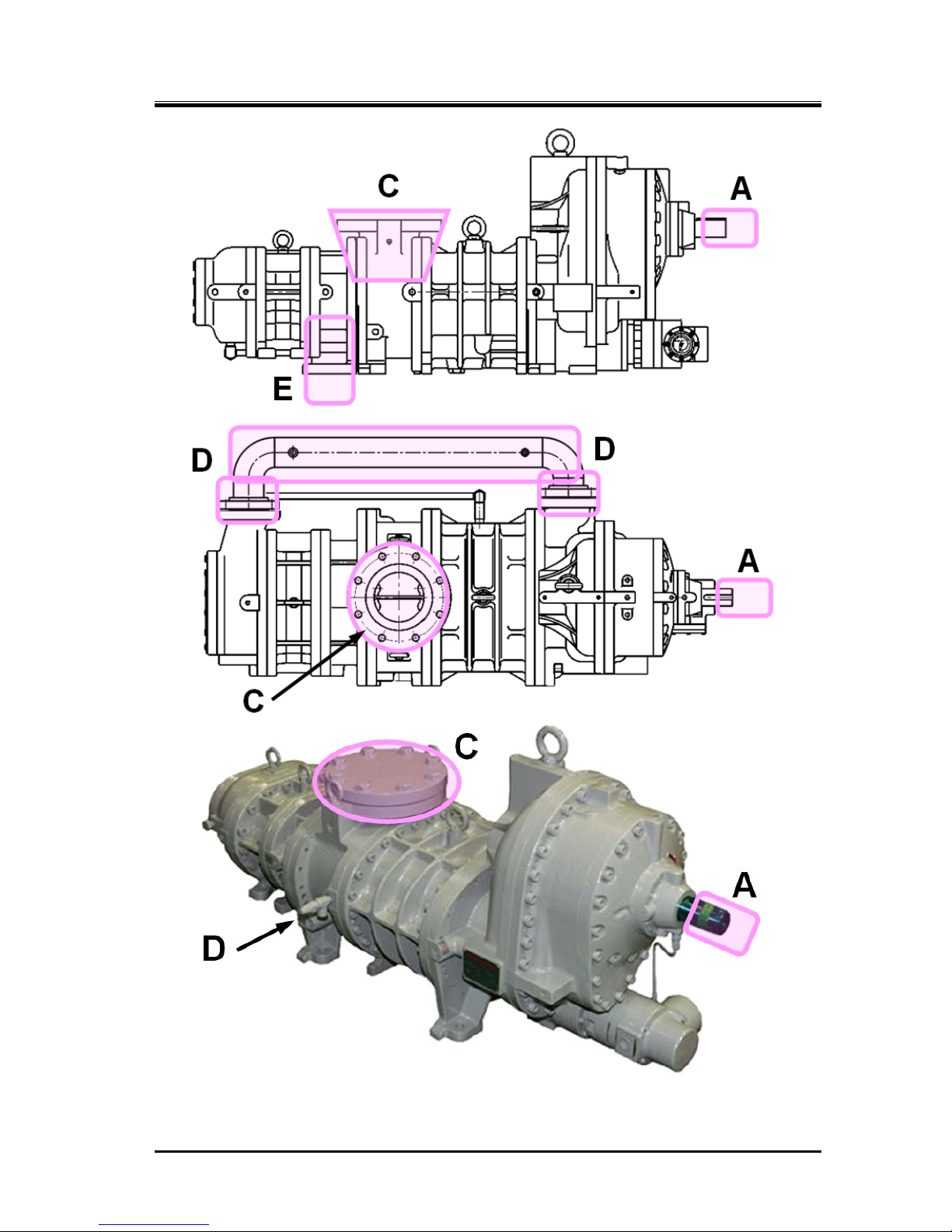
A
Motor and
compressor coupling
Refer to Figure 1-1
Caught in due to contact Install coupling cover
and prohibit opening.
Keep away.
Turn off motor main
power and control power,
and conduct
lockout/tagout.
B
Motor terminals
Electric shock caused by
contact with live wires or
electrical leakage
Keep away.
Do not open terminal
boxes.
Do not touch terminal
boxes.
Turn off motor main
power and control power,
and conduct
lockout/tagout.
C
Compressor
low-stage side
suction casing
Refer to Figure 1-1
Frostbite due to contact
Contact with or inhalation
of hazardous substances
generated by leakage of
refrigerant or the like
Keep away and do not
touch.
Wear protective gear.
Detect gas leakage.
Wear protective gear.
Work under room
temperature.
D
Compressor
intermediate piping
(low-stage discharge
port to high stage
suction port)
Refer to Figure 1-1
Burn injury due to contact
Contact with or inhalation
of hazardous substances
generated by leakage or
spout of refrigerant or the
like
Keep away and do not
touch
Wear protective gear
Gas leakage detection
Wear protective gear
Work in temperatures
below 40 °C
E
Compressor
high-stage side
discharge casing and
discharge piping
Refer to Figure 1-1
Burn injury due to contact
Contact with or inhalation
of hazardous substances
generated by leakage or
spout of refrigerant or the
like
Keep away and do not
touch.
Wear protective gear.
Detect gas leakage.
Wear protective gear.
Work at a temperature of
not higher than 40°C.
F
Check valves/service
valves and joints on
each section of the
package unit
Contact with or inhalation
of hazardous substances
generated by mishandling
or leakage
Frostbite or burn due to
contact
Sufficient ventilation
Indicate valve
open/close state.
Keep away and do not
touch.
Wear protective gear.
Sufficient ventilation
Wear protective gear.
Tagout for controlled
valve
G
Solenoid
valves/motor
operated valves on
each section of the
package unit
Electric shock caused by
contact with live wires or
electrical leakage
Pinched due to contact
with driving part
Install protective cover
on terminals, and
prohibit opening.
Keep away and do not
touch.
Wear protective gear.
Turn off each breaker and
the control power, and
conduct lockout/tagout.
Wear protective gear.
H
Electric components
in each section of the
package unit (oil
heater, protective
switch, etc.)
Electric shock caused by
contact with live wires or
electrical leakage
Pinched due to contact
with driving part
Install protective cover
on terminals, and
prohibit opening.
Keep away and do not
touch.
Wear protective gear.
Turn off each breaker and
the control power, and
conduct lockout/tagout.
Wear protective gear.
I
Package unit oil
drains
Contact with hazardous
substances generated by
leakage or spout
Burn caused by contact
with high-temperature
fluid
Sufficient ventilation
Keep away and do not
touch.
Wear protective gear.
Sufficient ventilation
Wear protective gear.
Work at a temperature of
not higher than 40°C.
J
Noises
Damage caused b y noise Wear protective gear.
—
2202L5JE-DA-C5-N_2015.05.
1. Safety
Compound 2-stage Screw Compressor 1.3 Residual Risks
1612LSC Speed Increaser Type
1-5
Figure 1-1 Locations of Hazardous Sources (compressor)
2202L5JE-DA-C5-N_2015.05.
1. Safety
Compound 2-stage Screw Compressor 1.4 Safety Devices
1612LSC Speed Increaser Type
1-6
1.4 Safety Devices
For safe use and protection of this product, make sure to attach safety devices to this product in
accordance with the regulations and the following instructions.
Safety devices cannot be kept in normal condition unless inspected and maintained at re gular intervals.
Their maintenance and inspection need to be performed as an important part of the
maintenance/inspection work project. Provide users of this product with necessary information on the
safety devices, for example, types of the safety devices, installation position, function, and inspection
method of safety related devices.
Check the safety devices after turning on the power and before operation of this
product. If they do not operate normally, immediately take repair or replace
safeties before starting this product.
1.4.1 Emergency Stop Button
Overview/Function/Purpose
The emergency stop buttons are used to stop the compressor operation immediately if an
emergency occurs in this product.
Installation Positions
On the control board and in the operation control room
Stop/Restoration Methods
The operating procedures for the emergency stop button, i.e., how to stop the operation and
restore the normal operating condition, must be clearly defined and the information provided to the
user of this product.
Inspection Method/Cycle
The emergency stop buttons must be tested before commissioning and must also be periodically
re-tested after that. The inspection procedures and the inspection interval for the emergency stop
button must be clearly defined and the information provided to the user of this product.
1.4.2 Breakers of Motor Main Power and Control Power
(with Lockout/Tagout Mechanism)
Overview/Function/Purpose
Turn off the main motor and control power, and if there is any possibility of danger during work
(especially during cleaning, maintenance, inspection, or troubleshooting), lockout/tagout devices
must be used on the breakers of the main motor and control powers to prevent injuries to workers in
case the power is turned on accidentally during work.
Methods of Performing and Releasing Lockout/Tagout
Make sure to clearly notify methods of performing and releasing lockout/tagout referring to the
regulations created by Occupational Safety & Health Administration (OSHA) or local governing
body.
Inspection Method/Cycle
The inspection procedures and the inspection interval for the lockout/tagout devices must be clearly
defined and the information provided to the user of this product.

2202L5JE-DA-C5-N_2015.05.
1. Safety
Compound 2-stage Screw Compressor 1.4 Safety Devices
1612LSC Speed Increaser Type
1-7
1.4.3 Compressor Protective Devices
Be sure to adjust the set values and check operation of the protective devices at
the commissioning.
Overview/Function/Purpose
These protective devices are used to protect this product.
Protecting from discharge temperature rise (DT)
This device stops the compressor operation when the discharge temperature of the
compressor exceeds the set value.
Install a temperature sensing port to the discharge pipe.
Protecting from oil temperature rise (OT)
This device stops the compressor operation when the oil temperature of the compressor
exceeds the set value.
Install a temperature sensing port to the package unit's oil supply pi pe (after the oil cooler).
Protecting from high pressure (HP)
This device stops the compressor operation when the discharge pressure abnormally rises
due to mishandling of the compressor or stoppage of cooling water supply to the condenser.
This device prevents explosion of the equipment and component s.
Install a pressure sensing port to the discharge pipe.
Protecting from intermediate pressure (IP)
This device controls the compressor appropriately when the intermediate pressure exceeds
the set value.
In some cases, this device stops the compressor operation.
Install a pressure output port to the package unit's intermediate gas pipe (or compressor's
intermediate gas pressure output port).
Protecting from suction pressure drop (LP)
This device stops the compressor operation when the suction pressure becomes below the
set value.
Install a pressure sensing port to the suction pipe.
Protecting from oil pressure (OP)
This device stops the compressor operation when lub ricating oil sup ply is not sufficient, the oil
filter is clogged, the refrigerant is mixed into the lubricating oil, and oil supply pressure
difference (from discharge pressure) becomes below the set value.
This device is to protect the compressor from wear and burnout.
Install a pressure sensing port to the package unit' s oil sup ply pipe (af ter the oil p ump) and the
discharge pipe.
Protecting from motor overcurrent (OCR)
This device controls the compressor appropriately when the current exceeds the set value. In
some cases, this device stops the compressor operation.
This device is normally installed in the compressor operation controller.
2202L5JE-DA-C5-N_2015.05.
1. Safety
Compound 2-stage Screw Compressor 1.4 Safety Devices
1612LSC Speed Increaser Type
1-8
Connection Positions and Settings
Specify the connection position and setting for each compressor protective device, and make sure
to provide users of this product with them.
Make sure that the set values do not exceed the operating limits shown in Chapter 2, section 2.3.2
and Table 2-2 of this manual.
Inspection Method/Cycle
Compressor protective devices require operation tests and confirmation of the settings calibration
before test run as well as at regular intervals.
Specify the inspection methods/intervals of the compressor protection devices, and make sure to
provide users of this product with such information.
In the operation test, check that alarms and protective devices operate norm ally
by using devices such as pressure tester. Do not operate the compressor with all
the valves closed, or in any other dangerous conditions.
If the protection from oil pressure (OP), high pressure (HP) activates, do not
restart operation until the cause of activation is removed.

2202L5JE-DA-C5-N_2015.05.
2 Compressor Specifications and Structure
Compound 2-stage Screw Compressor 2.1 Overview of the MYCOM 1612LSC Speed Increaser Type
1612LSC Speed Increaser Type
2-1
2 Compressor Specifications and Structure
2.1 Overview of the
Compound 2-stage
Screw Compressor 1612LSC Speed Increaser Type
The 1612LSC is a compound screw compressor integrating two stages of compressor
into a single body. The 1612LSC has been developed based on the LSC model of the 1612C Series
compressors —our most popular and long-selling products boasting the delivery of over 1000 units
worldwide since they were first put on the market— by adding the speed increaser gear system to
provide it with optimum performance for applications to ultra-cold and rapid freezing storage systems in
bonito and tuna fisheries.
Generally, screw compressors use oil injection to keep discharge temperature low during operation
without loss of volumetric efficiency even at high compression ratios, with singles-stage usage possible
even at evaporative temperatures near −40 °C.
However, for low-temperature regular usage, to improve KW/RT (the ratio of power consumption versus
cooling ability), a 2-stage compression method is used. To use standard-type screw compressors in a
2-stage compression method, at least two screw compressors must be combined so that there is a
high-stage and a low-stage, which requires multiple sets of machinery, power, and utilities, etc. to be
installed.
This 2-stage screw compressor combines these two units into one compound machine.
2.2 Model Designation of the Compressor
This manual describes the 1612LSC-*B*-52, -62, -53, -63, and -54 speed increaser type models.
The meaning of the type designation stamped on the nameplate of the compressor MODEL column is
as follows.
*1612LSC-*B*-52(62, 53, 63, 54)
2, 3 or 4
:Speed increaser gear ratio specification
( refer to the specifications table on the next page.)
5:Power frequency 50Hz (6:60Hz)
Vi of the high-stage discharge port specification (volume ratio),
as standard L port or M port
Means the machine (low-stage) booster
Vi of the low-stage discharge port specification (volume ratio),
as standard L port or M port
Means two-stage machine single unit
Shows the specifications of the high-stage rotor length,
only S for accelerator
speed increaser type
Shows the specifications of the low-stage rotor length, only L for speed increaser type
High-stage rotor
diameter of 125
Low-stage rotor diameter of 160
Means the working fluid
(Example: N = ammonia, F = Freon, P = Propane , HE = helium)
2202L5JE-DA-C5-N_2015.05.
2 Compressor Specifications and Structure
Compound 2-stage Screw Compressor 2.3 Compressor Specifications
1612LSC Speed Increaser Type
2-2
2.3 Compressor Specifications
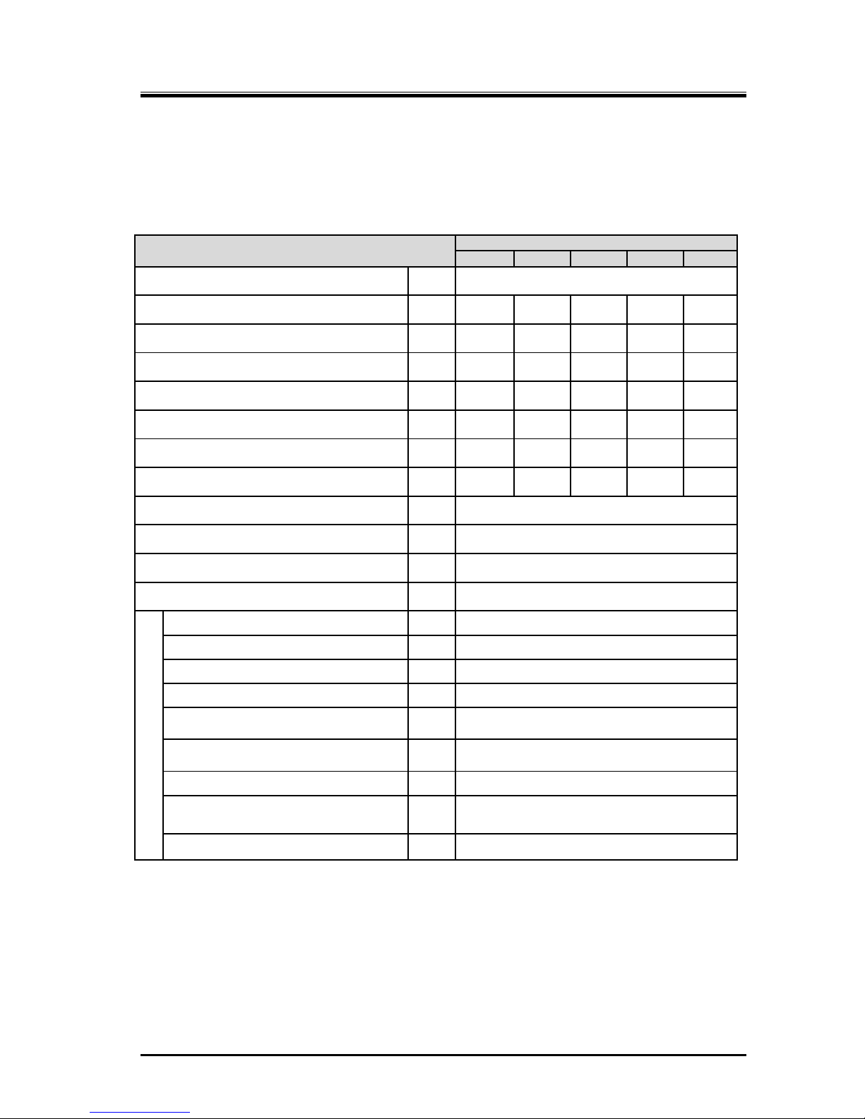
2.3.1 Standard Specifications
Table 2-1 1612LSC Speed Increaser Type Screw Compressor Specifications
Item
1612LSC Speed Increaser type
52 62 53 63 54
Product mass kg 560
Applied frequency Hz 50 60 50 60 50
Motor Poles - 4P 4P 2P 2P 2P
Speed increaser gear ratio - 1.809 1.809 1.220 1.220 1.472
Male rotor rotational speed min
-1
2610 3150 3610 4350 4350
Female rotor rotational speed min
-1
1740 2100 2407 2900 2900
Low-stage swept volume m3/h 551 665 762 918 918
High-stage swept volume m3/h 174 210 241 290 290
Applied refrigerant - Ammonia, Hydrofluorocarbon, other
Design pressure MPa 2.6
Capacity control range (Actual load) % 10 to 100
Rotation direction - Crockwise viewed from motor
Connection pipe size
Suction flange low-stage - MYCOM 125A (5″)
Discharge flange low-stage
- MYCOM 80A (3″)
Suction flange high-stage - MYCOM 80A (3″)
Discharge flange high-stage
-
MYCOM 65A (2½″)
Journal lubricating oil supply
(low-stage)
- Rc1/2
Journal lubricating oil supply
(high-stage)
- Rc3/8
Oil injection lubricating oil supply
- Rc3/8
Mechanical seal and speed increaser
gear lubricating oil supply
- Rc1/4
Capacity control - Load: Rc1/4, Unload: Rc3/8
In this manual unless otherwise noted, pressure units MPa represents the gauge pressure.
For usage temperature ranges and pressure ranges, refer to Section2.3.2 “Operation Limits”.
2202L5JE-DA-C5-N_2015.05.
2 Compressor Specifications and Structure
Compound 2-stage Screw Compressor 2.3 Compressor Specifications
1612LSC Speed Increaser Type
2-3
2.3.2 Operation Limits
Table 2-2 Operation Limits of 1612LSC Speed Increaser type
Items Operation Limits
Maximum discharge pressure MPa 1.96
Minimum suction pressure MPa −0.080
Maximum intermediate pressure MPa 0.588
Minimum intermediate pressure - > Suction pressure
Oil supply pressure
・ Maximum journal lubrication pressure MPa Discharge pressure + 0.39
・ Minimum journal lubrication pressure
MPa
Discharge pressure +0.049 and
Suction pressure +0.49
・ Minimum oil injection pressure MPa Suction pressure +0.49
Maximum Suction temperature °C 85
Minimum suction temperature °C −60
Maximum low-stage discharge temperature °C 90
Maximum high-stage discharge temperature °C 100
Maximum oil supply temperature °C 60
Minimum oil supply temperature °C 30
Maximum M (mail) rotor rotation speed min-1 4500
Minimum M (male) rotor rotation speed min-1 1450
Note : Unless otherwise noted, the pressure unit MPa represents the gauge pressure in this manual.
If operation at a indicated load of less than 30 % of capacity control is continued
for a long time except when starting up the machine, abnormal noises or
vibration may occur, so avoid doing so.
Repeating startup or shutdown operations in a short period of time is detrimental
for the starter and the motor as well as for the compressor itself. Refer to the
documentation of each device for the starting and stopping limitations of the
starter and the motor. After stopping the compressor, wait 15 minutes or more
before performing the next startup procedure.
2202L5JE-DA-C5-N_2015.05.
2 Compressor Specifications and Structure
Compound 2-stage Screw Compressor 2.3 Compressor Specifications
1612LSC Speed Increaser Type
2-4
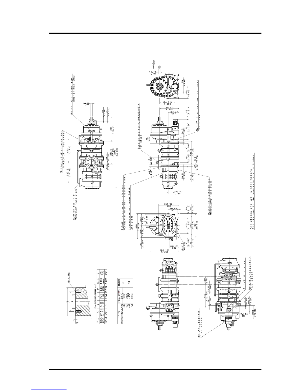
2.3.3 Outer Dimensions
Figure 2-1 1612LSC Speed Increaser Type Outer Dimensions
2202L5JE-DA-C5-N_2015.05.
2 Compressor Specifications and Structure
Compound 2-stage Screw Compressor 2.4 Structure of Compressor
1612LSC Speed Increaser Type
2-5
2.4 Structure of Compressor
For the names and locations of the compressor components, refer to Section 7.1 “Development
Views, Assembly Sectional Views” and Section 7.2 “Parts Configuration Table” in this manual.
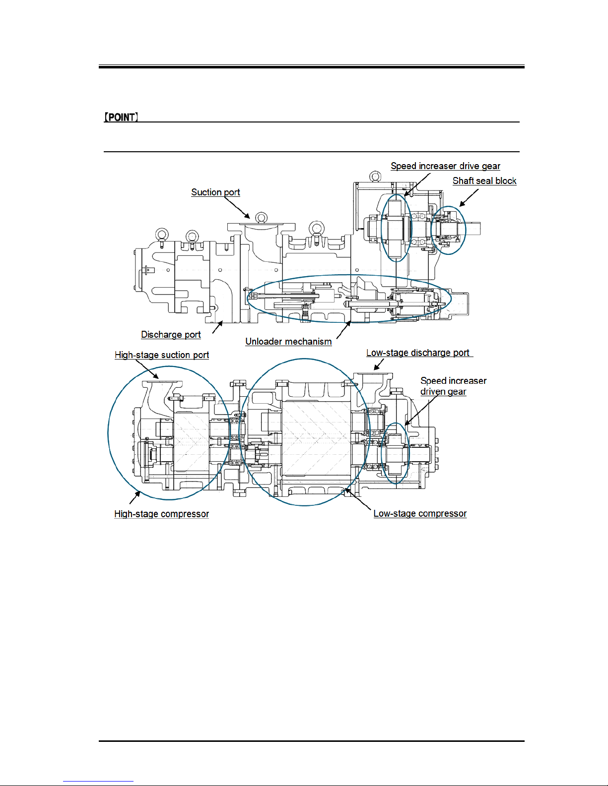
Figure 2-2 1612LSC Speed Increaser Type Sectional View
The 162LSC screw compressor consists of the following four main blocks: the shaft seal block which
prevents leakage of the refrigerant gas and lubricating oil from the compressor’s axis; the speed
increaser gear casing assembly which houses the drive and driven gears for increasing the rotating
speed of the electric motor’s output shaft; the low-stage compressor block which pressurizes
(pre-compresses) the gaseous working fluid coming from the freezing storage system; and the
high-stage compressor block which further compresses the working fluid gas pressurized by the
low-stage compressor before discharging it into the freezing storage system.
Like with the 1612**C Series direct drive type screw compressors, the 1612LSC speed increaser type
screw compressors has the capacity control (unloading) mechanism which works for reducing the
machine load at the time of the start of operation and keeping constant the load which would otherwise
vary during operation of the freezing storage system.
Inside each of the low-stage and high-stage compressor casings, there is a pair of screw rotors
meshing each other and supported by bearings at both ends. One of each pair is the male rotor having
four convex-shaped screw lobes and the other is the female rotor having six concave-shaped screw
lobes. In combination, they perform the work of compressing the refrigerant gas through the process
described in the next section.

2202L5JE-DA-C5-N_2015.05.
2 Compressor Specifications and Structure
Compound 2-stage Screw Compressor 2.5 Mechanisms
1612LSC Speed Increaser Type
2-6
2.5 Mechanisms
2.5.1 Basics of the Screw Compressor
The screw compressor is a positive displacement rotary comp ressor.
As shown in Figure 2-3 Compressor Mechanism, the refrigerant (gas) is continuously compressed by
changing the volume between the casing and the male and female meshed screw rotors, which have
different profiles.
The rotor with 4 protruding lobe sections is called the M rotor (male rotor), and the rotor with 6 lobe
depressions is called the F rotor (female rotor). Throughout this manual they are referred to as the M
rotor and F rotor.
The compressor M rotor shaft is driven by the two-pole or four-pol e motor via the spe ed i ncreaser ge ar.
Figure 2-3 Compressor Mechanism
2.5.2 Suction Process
As shown in Figure 2-4 Suction Process, the rotors’ different profiles mesh together. Also the volume
enclosed between the M and F rotor lobes and compressor casing increa ses from the suction side as
the rotors turn.
As rotations continue, at a certain point the volume reaches it s maximum, the rotors start to tra p the gas
between the lobes and compressor casing thereby isolating the gas from the suction port.
Figure 2-4 Suction Process
2202L5JE-DA-C5-N_2015.05.
2 Compressor Specifications and Structure
Compound 2-stage Screw Compressor 2.5 Mechanisms
1612LSC Speed Increaser Type
2-7
2.5.3 Compression Process
As the rotors further rotate, the sealing line between them moves toward the discharge side and the
volume between the rotor lobes decreases and compresses the trapped gas.
Figure 2-5 Compression Process Figure 2-6 Discharge Process
2.5.4 Discharge Process
Through the compression process, the volume between rotor lobes decreases to a predetermined
value at the discharge port.
Following rotor rotation, the compressed refrigerant gas is pushed out of the discharge port.
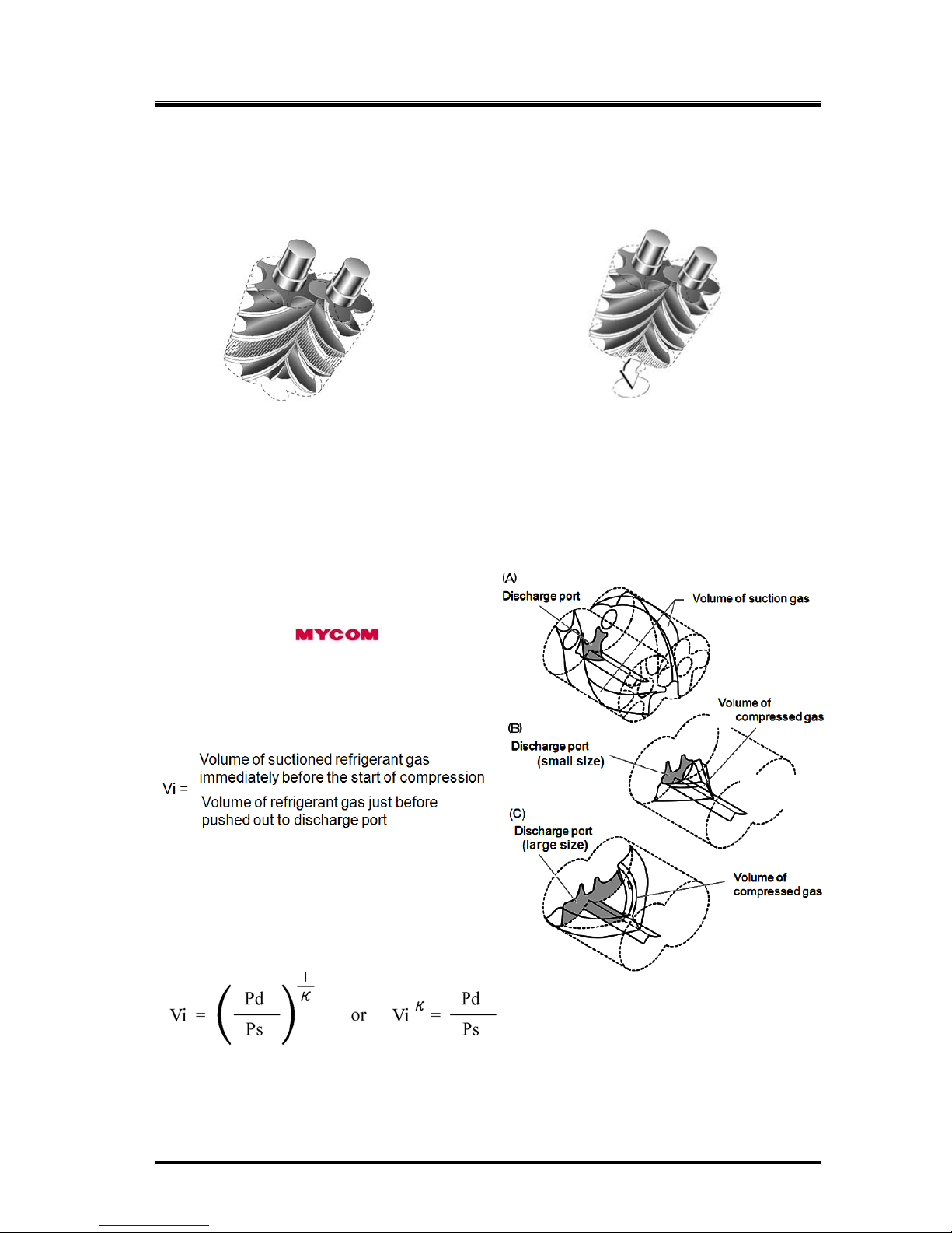
2.5.5 About Volume Ratio (Vi)
Volume ratios (Vi) of C-series screw
compressors are indicated in performance tables
or catalogs by using port symbols L and M.
The volume ratio represented by each symbol is
as follows:
L=2.63, M=3.65.
Which volume ratio (L or M) should be used is
decided according to operating conditions. If the
compressor is used with a volume ratio that does
not match operating conditions, operation will go
inefficiently wasting the power.
The relationship between volume ratios and
generally used compression ratios is as follows:
(Vi)
κ
= πi = Pd/Ps κ= Cp/Cv of refrigerant gas
Vi = designed volume ratio πi = designed compression ratio
The constant of the refrigerant gas also a factor, and the Vi value for the compression ratio will change
according to the refrigerant gas used.
Figure 2-7 Volume Ratio Explanation
2202L5JE-DA-C5-N_2015.05.
2 Compressor Specifications and Structure
Compound 2-stage Screw Compressor 2.5 Mechanisms
1612LSC Speed Increaser Type
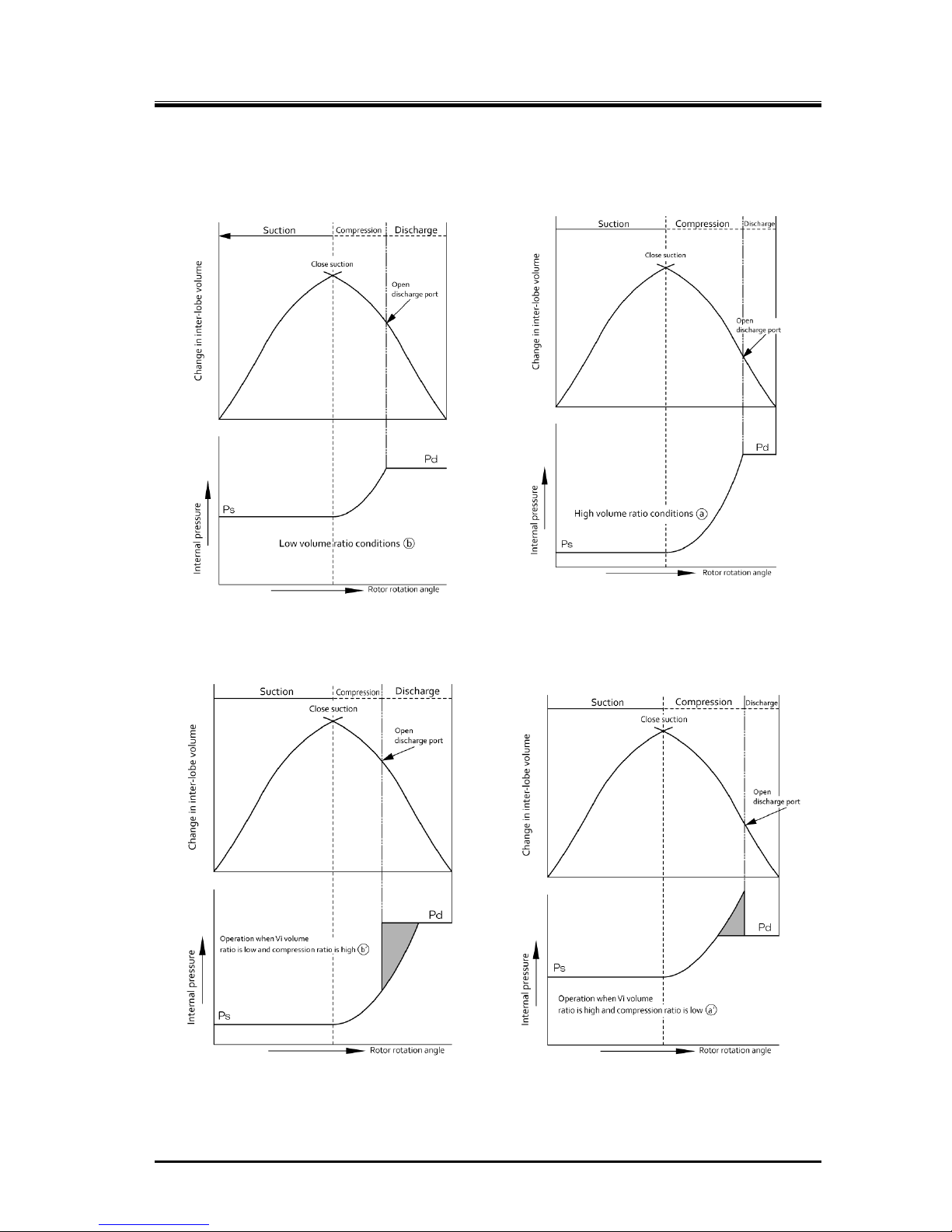
2-8
(A) When Vi matches operation conditions
The required compression ratio and Vi are both low The required compression ratio and Vi are both high
(B) When Vi does not match operation conditions
Vi is too low compared to
the required compression ratio
Vi is too high compared to
the required compression ratio
Figure 2-8 Relationship between volume ratio (Vi) and operation conditions
2202L5JE-DA-C5-N_2015.05.
2 Compressor Specifications and Structure
Compound 2-stage Screw Compressor 2.5 Mechanisms
1612LSC Speed Increaser Type
2-9
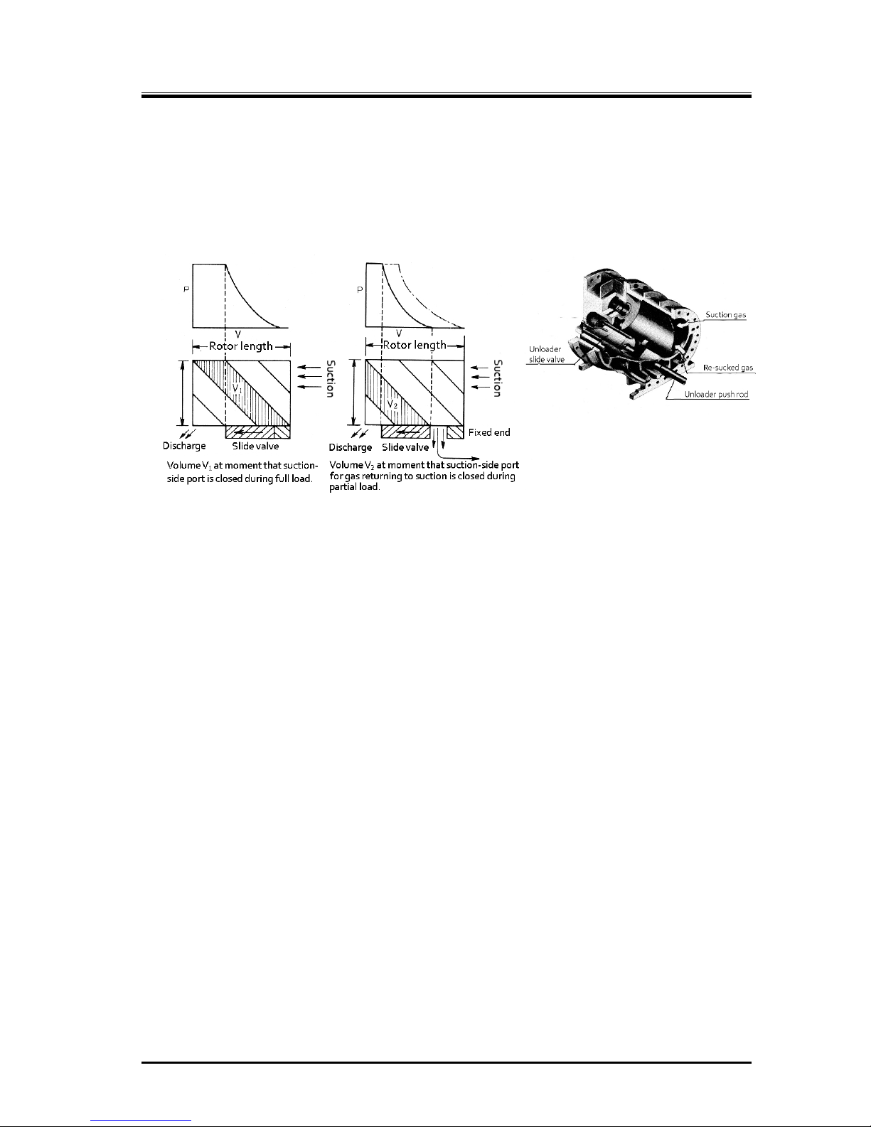
2.5.6 Capacity Control Mechanism
The capacity control structure involves the moving of a slide valve, bypassing suction gas just before
compression on the suction side, which shortens the portion of the rotor used for compression. The
slide valve is at the bottom of the casing where the rotors mesh together, and is constructed to move
parallel to the rotor’s axis. This movement is changed by a cam mechanism into rotation movement,
and as the position (capacity control ratio) is indicated externally, the electrical resistance value
changes to provide feedback to the automatic control circuit.
Figure 2-9 Capacity Control Mechanism
The 1612LSC speed increaser type has capacity control on the lo w-stage block only.
2.5.7 Bearings and Balance Piston
For the load created on the rotor perpendicular to the axle, a white metal-lined sleeve-type bearing is
used. The bearing uses surface fitted ball bearings with angular contact for loads along the axis
direction.
In particular, axial load for the M rotor, which has one type of helical gear, is comparatively larger than
that of the F rotor because of the thrust load from discharge pressure. This load for the M rotor is
reduced by the use of a thrust bearing, along with a balance piston providing opposing hydraulic
pressure.
2.5.8 Shaft Seal
To prevent refrigerant gas and oil leakage, a reliable mechanical seal assembly is used for the shaft
seal of the speed increaser gear spindle.
Mechanical seal assembly is mainly composed of "rotating ring" installed on the rotor shaft and
"stationary ring" installed in the seal cover. Rotating ring rotates with the shaft, and slides each other
with the stationary ring while maintaining a micron class gap. The sliding each other place is called as
the sliding surface.
As an example, for the BBSE (Balanced Bellows Single Seal)-type, which is a standard seal currently in
use, the fixed ring (mating ring) is cast iron, and the rotating ring is carbon, with an O-ring for the
packing.
Figure 2-10 Slide Valve in the
Rotor Casing
2202L5JE-DA-C5-N_2015.05.
2 Compressor Specifications and Structure
Compound 2-stage Screw Compressor 2.6 Gas and Oil Flow
1612LSC Speed Increaser Type
2-10
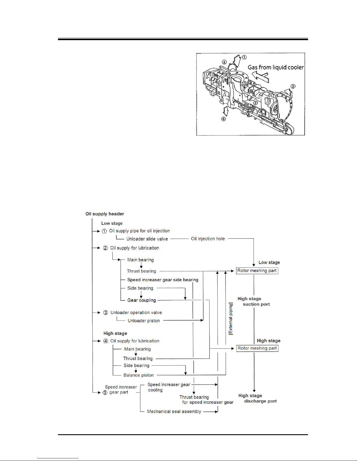
2.6 Gas and Oil Flow
The screw compressor’s compression process is
described earlier in this manual.
Gas for the compound speed increaser type 1612LSC
compressor passes from the evaporator and through
the suction strainer and check valve, and is sucked
into the center part of the compressor ①, and it is
compressed at the low-stage ② .Then the
compressed gas is discharged at ③. ③ and ④ are
connected by piping through which gas used for super
cooling is mixed in from the liquid cooler.
Lubricating oil injected at the low-stage is, while kept
mixed with gas, suctioned from ④ into the high-stage.
After being compressed at ⑤, the gas mixed with
lubricating oil is discharged from ⑥ to the oil separator, and then sent to the condenser.
The oil is cooled even without intermediate gas cooling, so the high-stage discharge temperature can
be maintained at below 90 °C.
Oil Supply Route
Lubricating oil is split into 4 flows as shown in Figure 2-12, and after providing lubrication, it is
mixed with discharge gas and leaves the compressor. In standard configurations, oil injection is not
performed at the high-stage.
Figure 2-12
1612LSC Speed Increas er Type Oil Supply Route
Figure 2-11 Gas Flow
2202L5JE-DA-C5-N_2015.05.
3 Installation
Compound 2stage Screw Compressor 3.1 General Precautions for Installation
1612LSC Speed Increaser Type
3-1
3 Installation
3.1 General Precautions for Installation
This chapter is based on the assumption that the compressor is installed to a standard
refrigeration/cold storage package unit.
If the package unit is not a standard refrigeration/cold storage package unit, prepare an
installation procedure manual referring to this chapter and considering safety precautions, before
installing the compressor.
If there are any questions, please contact our local sales offices or service centers.
In some cases, it may be required that installation is performed by qualified personnel.
Make sure that the work is performed by qualified personnel in compliance with local laws and
ordinances.
Read this chapter and related documents, and fully understand their contents before
performing installation.
Electrical work must be performed only by electrical engineers .
3.2 Installation Works
3.2.1 Unpacking
Check that there are no abnormalities such as damage on the compressor.
If there are abnormalities or deficient parts on the compressor, please contact our local sales
offices or service centers.
Unnecessary packaging materials should be discarded according to the laws and ordinances, or
your company’s rules.
3.2.2 Storage
If you need to store the compressor before installation, perform the followings:
Store it indoors.
Seal nitrogen gas in the compressor. (Pressure: approximately 0.15 MPa)
3.2.3 Transportation
Dropping of the lifted compressor may cause death or serious injury to the
worker. Do not allow anyone to be under the lifted compressor.
1. To lift the compressor, use lifting equipment with sufficient load capacity for the mass of the
compressor and appropriate lifting slings having proof load of more than the mass of compressor.
2. Secure sufficient space for safe lifting.
2202L5JE-DA-C5-N_2015.05.
3 Installation
Compound 2stage Screw Compressor 3.2 Installation Works
1612LSC Speed Increaser Type
3-2
3. Check the wire ropes before use. Thoroughly check the wire ropes for problems such as kinks,
knots, and broken strands. Do not start lifting unless the wire ropes have been verified and have no
problems. If you cannot make a correct evaluation or judgment, entrust an expert to inspect.
4. To lift the compressor, attach the wire ropes to the attached eyebolts using appropriate shackles
and hooks. The eyebolts are only used for lifting the compressor. Do not use the eyebolts to lift the
compressor with any attached apparatus.
The compressor eyebolts must not be used to lift the p ackage unit. To lift the package
unit, use the lifting chains on the compressor unit base periphery or other lifting
devices provided on the compressor unit base.
5. Check the transportation route for any obstacles in consideration of the compressor size.
6. Before lifting, check that the hook is located above the gravity center of the compressor.
7. Instruct all workers to move from near the work site before lifting.
8. Before lifting the compressor, alert all workers on the site of possible dangers of the lifting process
by signal (such as calling at the beginning of the work or making a signal by hand). Do not lift the
compressor unless the signals are completely understood by all personnel working together.
9. Slowly windup the wire ropes until shortly before the compressor leaves the ground.
10. Then, wind up the wire ropes a little further until the compressor is slightly away from the ground
and check that the compressor is balanced. If the compressor is inclined, return the compressor to
the ground and correct the inclination by adjusting the wire ropes. Then, restart the lifting operation.
11. Make sure to wind up the compressor slowly. Lifting it too quickly may damage the lifting equipment
including the wire ropes or part of the compressor.
12. When lifting the compressor, check the state of the wire ropes and lifting equipment. Check that the
compressor is not inclined.
13. When moving the lifted compressor, always use guiding ropes.
14. When moving the compressor, turn away workers from the movement direction and check safety.
15. Do not lift the compressor above any safety aisles unless absolutely necessary.
16. Do not put the compressor in a safety aisle. Always keep the safety aisle free of obstacles.
17. Remove any obstacles before putting down the compressor on the ground. The compressor should
not be inclined or unstable.
18. Before putting down the compressor on the ground, announce to the workers around the working
area.
19. When lowering the compressor onto two or more blocks, align the tops of blocks so that the
compressor becomes stable horizontally on them.
20. Lower the compressor slowly so that it does not get damaged due to impact.

2202L5JE-DA-C5-N_2015.05.
3 Installation
Compound 2stage Screw Compressor 3.2 Installation Works
1612LSC Speed Increaser Type
3-3
Outer Dimensions, Mass and Lifting Position
1612LSC speed increaser type common
Mass (kg) 560
Length (mm) 1372
Figure 3-1 Outer Dimensions, Mass and Lifting Position of Compressor
Lifted View

2202L5JE-DA-C5-N_2015.05.
3 Installation
Compound 2stage Screw Compressor 3.2 Installation Works
1612LSC Speed Increaser Type
3-4
3.2.4 Preparation for Installation
Installation Space
Prepare sufficient working space for easy operation, cleaning, maintenance, and inspection.
Illumination
Prepare lighting for easy operation, cleaning, maintenance, and inspection.
Ventilation
If natural ventilation is insufficient, install ventilation fans according to the regulations.
Piping
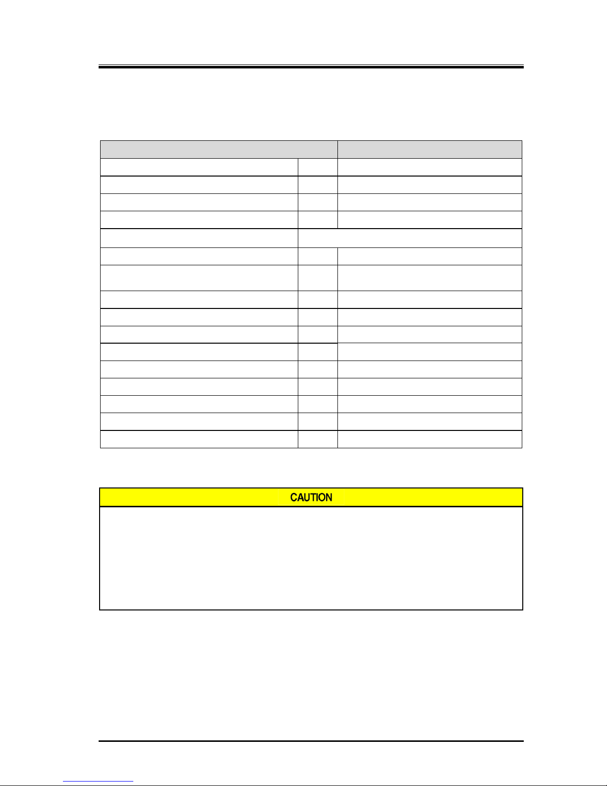
Table 3-1 Connected Piping List (Compressor)
Item Dimensions Remarks
Suction gas inlet MYCOM 125A (5″) See figure 3-2.
Low-stage gas outlet MYCOM 80A (3″) See figure 3-2.
High-stage gas inlet MYCOM 80A (3″) See figure 3-2.
High-stage discharge gas outlet MYCOM 65A (2½″) See figure 3-2.
Low-stage bearing (journal) oil inlet Rc1/2
Low-stage capacity control oil inlet (increase side) Rc1/4
Low-stage capacity control oil inlet (decrease side) Rc3/8
Oil injection inlet Rc3/8
Mechanical seal and speed increaser gear oil inlet Rc1/4
High-stage bearing (journal) oil inlet Rc3/8
D t g C N-h y
65A □144 4.5 101 144 4-M16 × P2 24
80A □154 4.5 119 158 4-M20 × P2.5 25
125A 270 5 174 230 8-M20 × P2.5 27
Figure 3-2 MYCOM Flange Dimensions
* In external dimensions figures 2-1 in “2.2.2 Outer
Dimensions” in chapter 2 of this manual, these
MYCOM flange dimensions are noted as MYK**A.

2202L5JE-DA-C5-N_2015.05.
3 Installation
Compound 2stage Screw Compressor 3.2 Installation Works
1612LSC Speed Increaser Type
3-5
3.2.5 Installation
3.2.5.1 Installation
Check that the surface of the package unit for compressor installation is even and horizontal. If it is not
flat and horizontal, tightening the bolts may lead to compressor deformation, and operation may be
affected.
3.2.5.2 Shaft Alignment between Compressor and Driving Machine
Turn off the main power and control power of the driving machine before shaft
alignment work between the compressor and the driving machine. Be careful so that
the power of instruments does not turn on during shaft alignment work. If the power
turns on during shaft alignment work, the driving machine starts moving and there is a
risk of being entangled with the rotating shaft.
At the time of turning ON/OFF each electric power breaker, make sure to prevent
electric shock.
For shaft alignment work between the compressor and driving machine, use designated
tools in normal condition. If a worn or damaged tool or a tool unsuitable for the work is
used, there is a risk of being injured.
In the case shaft alignment between the compressor and the driving machine, be sure that the
deviations within the range shown in the Table 3–2. However, if alignment tolerance of the driving
machine side is more stringent than Table 3-2, please adjust to the request within the allowable value of
the driving machine side.
T able 3– 2 Tolerance of Misalignment
Tolerance
Offset 6/100 mm
Angularity 3/100 mm (reference: Φ100 mm)
The Figure 3–3 and 3–4 show how to measure offset and angularity when performing the centering of
the shafts of the driving machine and this product using a dedicated hub, a dial gauge and a magnet
stand.
Figure 3-3 Measurement of Offset Figure 3-4 Measurement of Angularity

2202L5JE-DA-C5-N_2015.05.
3 Installation
Compound 2stage Screw Compressor 3.2 Installation Works
1612LSC Speed Increaser Type
3-6
3.2.5.3 Piping Connection
Refrigerant Piping
When connecting the refrigerant piping to the compressor, follow the instructions below.
The compressor is one of the few devices with moving components in the package unit.
The moving components are adversely affected by foreign substances within the system
(scale, dust, spatter, etc.). Therefore when connecting the piping, make sure that no such
foreign substances enter the piping.
In some compressors, in particular those shipped overseas, nitrogen gas is enclosed to
prevent rust. Release the pressure before starting piping work.
Do not allow moisture to enter the piping because it can cause trouble after starting operation.
Assemble piping when it is dry.
Cover flanges are attached to the low-stage gas outlet and the high-stage gas inlet of the
compressor, but after installation attach piping (intermediate piping) to both connection ports.
Inappropriate piping may cause operating problems such as oil not returning to the
compressor or liquid flowing back to the compressor.
When connecting piping to the compressor, as a general rule, use piping that is the same size
as the compressor connection port. If the size of the piping is smaller than the compressor
connection port, the flow of lubricating oil or refrigerant will be obstructed leading to problems.
Do not block flange or fittings with the mass of the piping connected to the compressor.
Prepare the appropriate support for piping.
3.2.5.4 Equipment and Devices for Protection of the Compressor
Oil Filter
According to the requirements of the use of the package unit or the standard to apply, install an oil
filter of appropriate filtration precision in the lubrication system of the compressor.
In the case of general applications such as closed-cycle refrigeration systems, we recommend to
use an oil filter with beta ratio in the range of β
20
≥ 150 that conforms to requirements of NAS 1638
class 8 or ISO 4406 17/15/13.
When the package unit requires API 619 4th/5th edition conformity, use an oil filter with beta ratio in
the range of β
10
≥200.
The oil filter may be clogged just after commissioning. We recommend installing two oil filters in
parallel. This will enable replacement of either filter during operation.
Oil Heater for Oil Separator
To preserve the temperature of the lubricating oil before starting the compressor, install an oil
heater on the oil separator. Make sure to install a protection function (thermostat, etc.) to prevent
overheating.
Suction Strainer
When compatible (inter-soluble) oil is used, the mesh size of suction strainer should be not less
than 200 meshes. When incompatible (non- inter-soluble) oil is used, it should be not less than 100
meshes.
For details about compatible and incompatible oils, refer to Section 4.1 "Lubricating Oil (Refrigerant
Oil)" in this manual Chapter 4.
During commissioning, small particles and scale may come from the system. We recommend to
install a finer filter temporarily.

2202L5JE-DA-C5-N_2015.05.
3 Installation
Compound 2stage Screw Compressor 3.2 Installation Works
1612LSC Speed Increaser Type
3-7
Compressor Protective Devices (Safety Devices)
To protect the compressor, install the protective devices as indicated in Section 1.4.3 "Compressor
Protective Devices" in this manual Chapter 1.
3.2.6 Airtightness Test
Perform an airtightness test on the package unit before starting commissioning. To prevent water entry
in the package unit, use nitrogen gas or dry air for the airtightness test.
3.2.7 Lubricating Oil Charge
TO select the lubricating oil to be used, refer to Section 4.1 "Lubricating Oil
(Refrigerant Oil)" in this manual.
When refilling lubricating oil, ensure that it i s clean and does not contain foreign
matters.
Be careful that air and water are not mixed in when refilling.
To ensure that the lubricating oil does not absorb air moisture, keep it indoors in
an airtight container until use.
3.2.7.1 Initial Charge of Lubricating Oil
Depending on the package unit configuration and operating condition, specify the procedure, method
and amount of the initial charge of lubricating oil, and make sure to provide users of this product with
such information.
In determining the procedure and work procedure of the initial charge of lubricating oil, please care oil is
to be filled in the oil filter and oil cooler always.
3.2.7.2 Additional Charge of Lubricating Oil
Specify the procedure of the additional filling of lubricating oil based on the configuration of the package
unit, and make sure to provide users of this product with the information.
3.2.8 Charge of Refrigerant
Depending on the use working fluid and equipment configuration of your package unit, specify the work
procedure that considered safety enough, and conduct the refrigerant initial filling work accordingly.
In addition, specify the procedure of the additional filling of refrigerant, make sure to provide users of
this product with the information.
3.2.9 Check after Installation
Depending on the package unit to which this product is installed, formulate the necessary confirmation
items and methods for package unit after installation and conduct them accordingly before the
commissioning. In addition, make sure to record and keep the results of your confirmation.

2202L5JE-DA-C5-N_2015.05.
4. Compressor and Package Unit Operation
Compound 2-stage Screw Compressor 4.1 Lubricating Oil (Refrigerant Oil)
1612LSC Speed Increaser Type
4-1
4. Compressor and Package Unit Operation
4.1 Lubricating Oil (Refrigerant Oil)
Lubrication management is very significant to keep the compressor in a good operating condition.
Take the following notes when managing lubricating oil.
4.1.1 Precautions for Selecting the Lubricating Oil
Selection of the lubricating oil should depend on the type of the refrigerant, the type of the
evaporator used with the compressor, and the conditions under which the compressor is
operated. Also to be considered when selecting lubricating oil are the properties of the oil that
include not only the viscosity but also such characteristics as compatibility in refrigerant,
separability from refrigerant, low temperature fluidity, high temperature thermal stability, etc.
We therefore recommend contacting our sales offices or service centers for choice of a
specified brand for your system.
Lubricating oil used for compressors must have a viscosity appropriate for lubricating the
bearings and other components in the compressors. The viscosity to be considered in this case
should be the viscosity the oil shows at the oil inlet of the compressor. The viscosity of the
lubricating oil significantly changes depending on the type of the refrigerant used in combination
with the lubricating oil. If the refrigerant dissolves in the lubricating oil (or the lubricating oil and
refrigerant are compatible), the viscosity of the lubricating oil drops to a level remarkably below
the level required for operation of the compressor under some operating conditions. On the
contrary, if the refrigerant does not dissolve in the lubricating oil (or the lubricating oil and
refrigerant are incompatible), the viscosity may become too high when the supply oil
temperature is low. For this reason, the lubricating oil must be selected such that it is supplied to
the compressor with an appropriate viscosity (kinematic viscosity of 13 to 40 mm
2
/s) in the
operating state.
The circulation of the lubricating oil for the entire system must be considered. After lubricating
and cooling each part of the compressor, the lubricating oil is discharged with refrigerant gas.
Most of the oil which is discharged from this compressor is trapped by the oil separator and is
cycled to the compressor. A small quantity of refrigerant oil goes to the condenser and the
evaporator. The lubricating oil is required to have sufficient fluidity and stability inside each part
in the refrigerating cycle where temperatures differ.
Note that some lubricating oils cannot be used depending on the combination with the
refrigerant. The following caution is an example case that is required especially attention.
Be careful since polyolester synthetic oil (POE) must not be used with ammonia
refrigerant.
4.1.2 Recommended Lubricating Oils
When selecting lubricating oil, not only compatibility with refrigerant but also effects on O-rings must be
considered. To prevent compressor malfunctions, we recommend the lubricating oil described below.
4.1.2.1 Recommended Lubricating Oils for Ammonia Refrigerant
Polyalkylene Glycols (PAG) Based Synthetic Oil (compatible oil)
Brand Kinematic viscosity (40°C) mm2/s Manufacturer Type
JOMO Freol PN46 46 JX Nippon Oil and Energy Corporation PAG

2202L5JE-DA-C5-N_2015.05.
4. Compressor and Package Unit Operation
Compound 2-stage Screw Compressor 4.1 Lubricating Oil (Refrigerant Oil)
1612LSC Speed Increaser Type
4-2
Mineral oils (incompatible oils)
Brand
Kinematic viscosity
(40°C) mm2/s
Manufacturer Type
SUNISO 3GS 30 Sun Oil Naphthene
base
SUNISO 4GS 55 Sun Oil
REFOIL NS 3GS 30 Nippon Oil
GARGOYLE ARCTIC C HEAVY 46 Exxon Mobil
GARGOYLE ARCTIC 300 68 Exxon Mobil
CAPELLA WF46 46 Texaco
CAPELLA WF68 64 Texaco
CP-1009-32 34 CPI Hydrotreated
paraffinic base
CP-1009-68 69 CPI
REFLO 46A 46 Petro Canada
REFLO 68A 58 Petro Canada
CAPELLA PREMIUM 67 Texaco
RHT-68 68 Kluber
REFLO XL 59 Petro Canada
Synthetic oils (incompatible oils)
Brand
Kinematic viscosity
(40°C) mm2/s
Manufacturer Type
Acemire 300 59 Acemire AB
Mycold AB68 53 BVA
ZERICE S46 46 Exxon Mobil
ZERICE S68 68 Exxon Mobil
BERREL FREEZE 46S 46 Matsumura Oil Co., Ltd.
CP-4700-32 31 CPI
CP-4700-68 56 CPI
Gold-Cold 300 53 Golden West
GARGOYLE ARCTIC NH68 64 Exxon Mobil PAO+AB
REFLO SYNTHETIC 68A 62 Petro Canada
Gargoyle arctic SHC 224 Note 30 Exxon Mobil PAO
Gargoyle arctic SHC 226(E) Note 68 Exxon Mobil
Note: Use only a seal of the standard BBSE type.
4.1.2.2 Oils for Systems Using Hydrofluorocarbon (HFC) refrigerants
Polyolester synthetic oil (POE) for R404A, R507A and R410A
(compatible synthetic oil)
Brand Kinematic viscosity (40°C) mm2/s Manufacturer Type
SUNISO SL-68S 67 Sun Oil POE
EMKARATE RL68H 72 Lubrizol

2202L5JE-DA-C5-N_2015.05.
4. Compressor and Package Unit Operation
Compound 2-stage Screw Compressor 4.1 Lubricating Oil (Refrigerant Oil)
1612LSC Speed Increaser Type
4-3
Polyolester Synthetic Oil (POE) for R134a (Incompatible synthetic oil)
Brand Kinematic viscosity (40°C) mm2/s Manufacturer Type
JOMO Freol α100 107
JX Nippon Oil and
Energy Corporation
POE
When using lubricating oil of a br and not described in this section, or when using
lubricating oil along with refrigerants or gases not described in this section,
please contact us.
4.1.3 Change of Lubricating Oil Brand
When changing the lubricating oil brand in currently use for some reason, attention must be paid to the
following points.
The change of lubricating oil brand may cause problems in operating conditions and
the compressor. When changing the lubricating oil brand in use, make sure to
contact us because appropriate steps must be surely followed.
Package unit composition differs depending on the characteristics of lubricating oil
(compatible/incompatible with refrigerant). As a general rule, changing compatible oil
to incompatible oil or vice versa is not allowed.
Lubricating oil contains various additives to fulfill necessary lubricating conditions. Types of
additives and their mixing ratio depend on each oil brand. We, therefore, recommend to avoid
mixed use of different brands of lubricating oil. If mixed brands of lubricating oil are used, the
different additives in the lubricating oil may react with each other and produce foreign
substances like slurry.
If it is necessary to change the brand of lubricating oil, collect as much as oil as possible from
the compressor as well as from the condenser, evaporator, and all other refrigerating unit
components before charging the new lubricating oil. After 100 to 200 hours of operation, replace
the oil again.
If lubricating oil manufacturers differ, contact both of them and inquire whether the changing is
appropriate. The same confirmation is required for changing the brand even if it is of the same
manufacturer.
There is no problem in changing the viscosity level within the same brand. However, make sure
that the viscosity grade will not cause problems during operation (Example : SUNISO
3GS→SUNISO 4GS).

2202L5JE-DA-C5-N_2015.05.
4. Compressor and Package Unit Operation
Compound 2-stage Screw Compressor 4.1 Lubricating Oil (Refrigerant Oil)
1612LSC Speed Increaser Type
4-4
4.1.4 Precautions for Handling lubricating Oil
When refilling lubricating oil, ensure that it is clean and does not contain foreign matters.
Be careful that air and water are not mixed in when refilling.
To ensure that the lubricating oil does not absorb air moisture, keep it indoors in an airtight
container until use.
4.1.4.1 Precautions for Handling Polyalkylene Glycol (PAG)
PAG oil is much more hygroscopic than mineral oils and any moisture mixed in the oil may lead to rust,
corrosion and wear within the package. When handling PAG oil, pay special attention to the following
points.
Do not perform oil charging in rainy weather or at a place with high humidity to prevent
absorbing moisture.
Before charging, remove as much moisture as possible from the system by exhausting it with
a vacuum pump for a sufficient length of time and leaving the system in vacuum condition
overnight.
Do not open the lid of pail (oil container) until just before charging. Once the can is opened,
finish the oil charge as quickly as possible. (Finish the charge of a single can of oil within 15
minutes.)
Cover any gaps between the pail opening and the charge hose so that foreign substances or
moisture cannot enter. A more effective way is to substitute any space inside the pail with
nitrogen gas.
Always charge all oil from the pail. Even if some oil remains, do not use it subsequently.
If any oil drops on a painted surface, wipe it away as soon as possible. Otherwise the paint
may come off.
4.1.4.2 Precautions for Handling Polyolester (POE) Oil
This type of oil has high hygroscopicity as polyalkylene glycol, and also exhibits hydrolyzability under
high temperature environments. Moisture entry must be avoided. Therefore, special attention must be
paid as with PAG when handling POE.
Finish the charging in as short a time as possible after opening the pail to minimize exposure
to air.
Make sure that all oil in a pail is used in a single charging. Any remaining oil must be stored
indoors with the can lid closed tightly. Do not attempt to store it for a long time.
Because POE can hydrolyze, make sure to perform an oil analysis regularly in the package to
see if any abnormal conditions are present.

2202L5JE-DA-C5-N_2015.05.
4. Compressor and Package Unit Operation
Compound 2-stage Screw Compressor 4.1 Lubricating Oil (Refrigerant Oil)
1612LSC Speed Increaser Type
4-5
4.1.5 Lubricating Oil Management Criteria
Lubricating oils that are managed by the criteria are classified into the following categories:
(1) Synthetic oils: Polyalkylene glycols (PAG)
(2) Mineral oils: Naphthenic base oils and paraffinic base oils
(3) Synthetic oils: Alkylbenzene (AB) and Polyalphaolefine (PAO)
(4) Synthetic oils: Polyolesters (POE)
Oil sampling and analysis is recommended every six months.
If the following control criteria are not satisfied, replace the oil.
◆ Note that the water content of PAG shall be excluded from the above oil replacement criteria.
Refer to the Note in the following table.
The analysis items and the criteria are shown in the following tables. Please note that these
management criteria may be changed without notice.
Table 4-1 Synthetic Oil (PAG)
Item Criteria
(a) Color phase ASTM color scale: 4.0 or less
(b) Total acid number (TAN) 0.1 mg KOH/g or less
(c) Kinematic viscosity Within ±10 % from that of fresh oil
(d) Water content 2000 mass ppm or less Note
(e) Degree of contamination Degree of contamination measured by mass method (Millipore
value) shall be 15 mg/100 mL or less
Table 4-2 Mineral Oil and Synthetic Oil (AB, PAO)
Item Criteria
(a) Color phase ASTM color scale: 6.0 or less
(b) Total acid number (TAN) 0.3 mg KOH/g or less
(c) Kinematic viscosity Within ±15 % from that of fresh oil
(d) Water content 100 mass ppm or less
(e) Degree of
contamination
Degree of contamination measured by mass method (Millipore
value) shall be 15 mg/100 mL or less
Table 4-3 Synthetic Oil (POE)
Item Criteria
(a) Color phase ASTM color scale: 4.0 or less
(b) Total acid number (TAN) 0.2 mg KOH/g or less
(c) Kinematic viscosity Within ±10 % from that of fresh oil
(d) Water content 200 mass ppm or less
(e) Degree of
contamination
Degree of contamination measured by mass method (Millipore
value) shall be 15 mg/100 mL or less
Note: Synthetic oils (compatible with ammonia) are so highly hygroscopic that they can absorb
moisture at the time of sampling. In addition, the ammonia content they have absorbed
may be detected as the water content at the time of the analysis, making it difficult to
precisely measure the water content. Thus, use the criterion value only as a reference.

2202L5JE-DA-C5-N_2015.05.
4. Compressor and Package Unit Operation
Compound 2-stage Screw Compressor 4.1 Lubricating Oil (Refrigerant Oil)
1612LSC Speed Increaser Type
4-6
4.1.6 Lubricating Oil Replacement Timing
4.1.6.1 After Starting the Initial Operation
As the oil can easily be contaminated and degraded relatively quickly during the initial operation due to
scales and deposits remaining in piping and vessels, be sure to sample and analyze the oil after 500
hours of operation.
If it is found as a result of the analysis that the criteria given in Tables 4-1 to 4-3 are not satisfied, the oil
must be replaced.
4.1.6.2 During Normal Operation
Lubricating oils will degrade gradually as the system is operated over time.
The rate of degradation depends on the operating condition, type of oil and amount of foreign matters
and moisture contained in the oil.
The lubricating oil must be sampled and analyzed every six months. If it is found as a result of the
analysis that the control criteria given in Tables 4-1 to 4-3 are not satisfied, the oil must be replaced.
If the oil filters are frequently clogged or the oil color quickly becomes darker and unclear, replace the
oil after removing the cause of the problem.

2202L5JE-DA-C5-N_2015.05.
4. Compressor and Package Unit Operation
Compound 2-stage Screw Compressor 4.2 Precautions for Operation
1612LSC Speed Increaser Type
4-7
4.2 Precautions for Operation
If the package unit is used in the refrigeration cycle, please keep in mind the contents of this section in
particular.
4.2.1 Prevention of Liquid Flow-back
Liquid flow-back is a phenomenon where refrigerant that did not completely evaporate with the gas
reaches the compressor. Liquid flow-back may cause insufficient lubrication of the compressor,
abnormal vibrations and noises, and abnormal foaming of lubricating oil (too much oil loss). To prevent
liquid flow-back, properly adjust the expansion valve of each liquid cooler. For details, refer to Chapter 6
"Troubleshooting" in this manual.
4.2.2 Purging of Non-Condensable Gases
Some types of refrigerants emit bad smells or toxic gases. Make sure to ventilate
the air during work.
If there is a leak on the low-pressure side of the refrigeration cycle, air may enter the package unit.
If non-condensable gas like air enters the unit, the condensing pressure rises and the energy
consumption increases. This leads to uneconomical operation.
Follow the procedure below to check for non-condensable gases.
1. When the compressor is stopped, allow the cooling water to flow to the unit's condenser for at
least 15 minutes. Check the condensing pressure by using the pressure gauge of the compressor.
2. Check the cooling water temperature.
3. Compare the condensing pressure checked in step 1 above with the refrigerant saturation
pressure that depends on the cooling water temperature (as shown in the table b elow).
T able 4-4 Ty pical Refrigerant Temperature and Saturation Pressure
■ Unless otherwise noted, the pressure unit MPa represents the gauge pressure in this manual.
4. When the pressure inside the condenser and the refrigerant saturation pressure that depends on
the cooling water temperature are approximately equivalent, non-condensable gases do not exist.
When the pressure inside the condenser is 0.05 MPa or more higher than the refrigerant
saturation pressure that depends on the cooling water temperature, there is a possibility of
non-condensable gases entering the unit. In that case, purge the non-condensable gases from
the condenser .
T emperature °C
Pressure MPa
Ammonia R404A R507A R410A R134a
0 0.328 0.509 0.523 0.699 0.192
4 0.396 0.590 0.606 0.807 0.237
8 0.472 0.678 0.696 0.924 0.287
12 0.557 0.775 0.795 1.053 0.342
16 0.652 0.881 0.903 1.193 0.403
20 0.756 0.996 1.021 1.346 0.471
24 0.871 1.121 1.148 1.513 0.545
28 0.998 1.256 1.286 1.693 0.626
32 1.137 1.401 1.435 1.887 0.714
36 1.289 1.559 1.595 2.098 0.811
40 1.454 1.728 1.768 2.324 0.916

2202L5JE-DA-C5-N_2015.05.
4. Compressor and Package Unit Operation
Compound 2-stage Screw Compressor 4.3 When Stopping the Compressor for a Long Time
1612LSC Speed Increaser Type
4-8
4.3 When Stopping the Compressor for a Long Time
When stopping the compressor for a long period of time, make sure to perform the following steps.
Turn off the motor main power.
Turn off the heater power and control panel power.
Close the suction and discharge side shut-off valves.
If the operation stop period is 1 month or longer, perform the following checks.
Operate the oil pump for 10 seconds per week.
After that, rotate the compressor shaft (10 rotations or more).
Measure the package unit pressure once per month.
Check for refrigerant leakage once per month.
When restarting the compressor after an operation stop period of 1 year or longer, check the system for
refrigerant leak and analyze the lubricating oil.
If it is found as a result of the analysis that the control criteria given in this Chapter, Section 4.1.5 Tables
4-1 to 4-3 are not satisfied, the oil must be replaced.
Also check the motor insulation resistance.
Supply power to the oil heater at least 1 day before operation start.
Before starting the operation, confirm that the refrigerant is not condensed in the package unit by
checking the package temperature and pressure.

2202L5JE-DA-C5-N_2015.05.
5 Maintenance and Inspection
Compound 2-stage Screw Compressor 5.1 Precautions for Maintenance and Inspection
1612LSC Speed Increaser Type
5-1
5 Maintenance and Inspection
5.1 Precautions for Maintenance and Inspection
When reading this Section, also refer to Section 1.1 in this manual Chapter 1.
When entering the machine room for maintenance ser vices, ensure that sufficient
ventilation has been started and measure the oxygen concentration so that there is
no risk of oxygen deficiency. The ventilation must be continued steadil y until the
work is completed.
For performing the inspection work, be sure to prepare safety shoes, protective
glasses, gas mask and other proper protective equipment and do not fail to use
them whenever they are required.
After stopping the machine and before working on a regular inspection or overhaul,
be sure to shut off the main motor power, control power, and other power to each
equipment and valve. After they are shut off, be sure to make the switches
inoperable by others. Also, be sure to attach notification tags to prohibit operation
(lock-out/tag-out).
When any manual stop valve has been closed, be sure to make the valve
inoperable by others and put a notification tag to prohibit the operation (tag-out).
When the compressor is to be overhauled, check that the internal pres sure of this
product is at the atmospheric pressure before starting the work.
When using lifting devices, e.g. a crane, etc. and/or lifting tools, ensure that they
can sufficiently withstand the load.
When lifting a heavy load object, do not allow anyone’s body to put under it.
The work to turn each power supply ON/OFF or operate a lifting unit must be
exclusively performed by qualified personnel.
When using electric tools, ensure that they are properly managed in accordance
with each instruction manual. Especially before using and while using, be sure to
follow the care instructions on the safety of each instruction manual.
Be sure to use only genuine parts for replacement. Using parts that are
not genuine can cause damage to this product or other devices during operation.
Do not convert or modify this product or its components without prior permission
from MAYEKAWA. Otherwise, it can lead to an unexpected accident.
Exercise sufficient care for handling a heavy load, and use such a lifting device as a
crane or work with an adequate number of personnel commensurate with the
magnitude of the weight. Also, be sure to use stud bolts (safety retention bolts) and
other support tools for the work. Neglecting the above warning can lead to low back
pain of the worker or injury due to dropping of the parts.
If two or more people are to work together, be sure to clearly define the work
procedures to share a common understanding among all workers before performing
the work.
Not only the work to turn each power supply ON/OFF or operate a lifting device, but
also any type of work requiring qualification must be exclusively performed by
qualified personnel.

2202L5JE-DA-C5-N_2015.05.
5 Maintenance and Inspection
Compound 2-stage Screw Compressor 5.1 Precautions for Maintenance and Inspection
1612LSC Speed Increaser Type
5-2
When checking the operation data of units and executing other daily maintenance
services, pay particular attention to avoid touching the area heated to a high
temperature causing skin burns or inadvertently moving the handle of a valve
leading to an erroneous operation.
In the disassembly/inspection workplace, secure a sufficient space for temporary
storage of the removed parts and tools, replacement parts, and for the
disassembling work as well as safety passages, and then put up necessary off-limit
signs.
In the workplace, secure a sufficient space and refrain from putting tools directly on
the floor or from haphazardly laying wires.
Keep the floor clean all the time. Leaving the floor smeared with oil and the like
causes it to be slippery and may result in the fall and injury of personnel. Thus, do
not leave it but wipe it off right away.
Make sure that the temperature of the high temperature sections such as head
covers and discharge lines has been cooled down to normal ambient temperature,
before working on them.
When disassembling and reassembling the compressor, use the specified tools
properly. Before starting to use those tools, gain the full understanding of their
characteristics and the method for use.
During the maintenance service, keep the tools clean all the time. Using those tools
smeared with oil increases the risk of slip and fall, leading to an injury. Also during
the service, there is a risk of foreign matters intruding inside the compressor to
cause its damage.
Parts are slippery with oil. Fully watch out for the risk of any object falling down.
Pay attention to any parts falling down, which could lead to personal injury.
Before disassembly, inspections, and handling of the compressor, sufficiently
understand the disassembly and assembly procedures.
This manual is not intended to provide complete disassembly and assembly
procedures for the compressor. Instead, it describes only the important points in
relation to the maintenance service of the compressor.
If complete disassembly and assembly of the compressor are required, please
contact your nearest sales office or service center of MAYEKAWA.
When removing a part, be careful not to damage it.
Place the removed parts on a clean workbench in an orderly manner.
For cleaning parts, use kerosene and/or machine parts cleaner.
Washed parts shall be dried by compressed air or wiped up using clean cloth. Do
not use synthetic textiles or woolen textiles to prevent fibers from attaching the
parts.
When separating the assembled compressor casings, sometimes it is difficult to
separate them due to the gasket stuck. In such a case, never hammer in a screw
driver or flat chisel into the gap. Screw jack bolts using the screw holes to separate
the casing each other. When some gap is observed between them, use a scraper
to remove one side of the gasket from the surface.
Removed bolts from each part should be classified into each used section to
prevent confusion.

2202L5JE-DA-C5-N_2015.05.
5 Maintenance and Inspection
Compound 2-stage Screw Compressor 5.2 Maintenance and Inspection List
1612LSC Speed Increaser Type
5-3
5.2 Maintenance and Inspection List
5.2.1 Daily Management
As daily management, check the items listed in Table 5-1 "Daily Inspection Items" and record the
results.
Logging these operation data on a daily basis aid in finding out any abnormal conditions of the
compressor. This is significantly effective in preventing compressor failures.
It is particularly important to check whether the temperature/pressure correlations related to the
refrigerant evaporation and condensation is proper. This makes it possible to quickly find out problems
in the compressor or the system.
If a failure or accident should occur in the compressor or the system, the operation logbook will help
determine the cause and take prompt and proper actions.
T able 5-1 Daily Inspection Items
Inspection Items Inspection Contents Check Points and Actions
Compressor
Operating hours hr Total operating hours Judgment of periodic
maintenance timing
Suction pressure
MPa
Note 1
Difference from the set value
of evaporation temperature
equivalent pressure
Contamination on the cooling
pipe surface
Temperature, flow rate, etc. of
the object to be cooled
Intermediate pressure MPa Pressure difference from
rated operation (normal
value)
If it is too high, check high-
stage. If it is too low check
low-stage.
Discharge pressure Mpa Difference from cooling water
temperature equivalent
condensing pressure
Contamination on condenser
cooling pipes
Non-condensable gases mixed
into the system
Quantity, temperature, etc. of
cooling water
Oil supply pressure MPa Difference from discharge
pressure
Whether differential pressure is
decreasing
Operation with liquid flow-back
Whether compressor parts are
worn
Oil filter pressure loss MPa Pressure difference between
oil filter inlet and outlet
Contamination of lubricating oil
Clogging of oil filter element
Suction temperature °C Whether within upper and
lower limits
Temperature, flow rate, etc. of
the object to be cooled
Degree of superheat
for suction
°C Whether degree of
superheat is proper
Adjust expansion valve
Insufficient refrigerant flow
Intermediate
temperature
°C Whether within upper and
lower limits
Adjust intermediate expansion
valve
Discharge
temperature
°C Whether within upper limit Non-condensable gases mixed
into the system
Oil supply temperature,
insufficient oil supply
Compressor failure

2202L5JE-DA-C5-N_2015.05.
5 Maintenance and Inspection
Compound 2-stage Screw Compressor 5.2 Maintenance and Inspection List
1612LSC Speed Increaser Type
5-4
Inspection Items Inspection Contents Check Points and Actions
Oil supply
temperature
°C Whether within upper and
lower limits
Contamination on cooling pipes
of oil cooler
Capacity control
Indicated load
%
Whether operation is normal Damage to solenoid valve coil
Improper adjustment of manual
control valve of
electromagnetic assembly
Leak from
mechanical seal
ml Leak per hour Mechanical seal failure
Noise and vibration Abnormal noise/vibration Compressor failure
Others
Motor current A Whether it is higher than the
current at test run
Compressor/Motor failure
Oil level of oil
separator
- Oil level Oil loss
Replenish oil
Fluid level in the
receiver
- Fluid level Replenish refrigerant
Check for refrigerant
leak
-
leak or not Inside the machine room and in
the facility on the load side
Note 1 : Unless otherwise noted, the pressure unit MPa represents the gauge pressure in this
manual.
Daily Maintenance Items
1. Lubrication oil level
When the oil level in the oil separator reaches the lower limit, charge lubricating oil by referring to
the instruction manual of the unit.
2. Replacing oil filter element
When the differential pressure between the inlet and out let ports of the oil filter exceeds 0.1 MPa,
replace the oil filter element.
At the beginning of the operation, the differential pressure of the oil filter may increase quickly.
3. Cleaning of suction strainer
When the compressor operating hours exceeds 500, check the suction strainer. If a temporary
filter is installed for the initial stage of operation, remove it.
At the beginning of the operation or after periodical check, the differential pressure between the
front and back of the suction strainer may increase quickly. If the differential pressure becomes
large, check and clean the suction strainer.
4. Lubricating oil leak rate from mechanical seal
If much oil leaks from the mechanical seal, determine the leak rate per hour. The following table
shows guidelines for allowable leak rate and the rate at which inspection must be done.
If any problem (damage, etc.) is found in mechanical seal, replace the mechanical seal.
T able 5-2 Guideline for Leak from Mechanical Seal
1612LSC
Allowable leak rate ≤ 3 ml/hr
Rate at which inspection must be done ≥ 9 ml/hr
Note: The specifications above are just guidelines. They are not guaranteed values.
5. Contamination on the cooling water side of the cooling pipes of condenser and oil cooler
Clogging and contamination of the cooling pipe is largely affected by the quality of cooling water.
When the oil temperature and discharge pressure gradually rise during the initial stage of
operation, inspect and clean the cooling water side of oil cooler and condenser even when the
time has not yet come at which inspection must be done.
Compressor

2202L5JE-DA-C5-N_2015.05.
5 Maintenance and Inspection
Compound 2-stage Screw Compressor 5.2 Maintenance and Inspection List
1612LSC Speed Increaser Type
5-5
5.2.2 Periodic Inspection
Conduct inspection for the following items according to the specified intervals.
In addition, observe relevant laws and regulations on the inspections and recording of the results that
are provided for other related items such as any safety devices (e.g. gas leak detectors), or other utility
(gas/electricity) protection devices that constitute the cooling package unit together with the
compressor.
Table 5-3 Periodic Inspection Items
Item Inspection interval and Con ten t Remarks
Pressure gauges/
pressure sensors
Yearly inspection
Thermometers/
temperature sensors
Yearly inspection
Protection devices and
safety valves
Yearly inspection
Suction strainer Inspect after 500 hours from the start
of operation.
If the differential pressure between
the front and back of the suction
strainer increases, check and clean
the suction strainer.
Yearly inspection and cleaning
Lubricating oil Analyze lubricating oil after 500 hours
from the start of operation.
Replace the oil if the analysis result
does not satisfy the control criteria
given in Section 4.1.5.
Analyze oil every 6 months.
Oil filter element Yearly replacement Replace the filter element if the
differential pressure between the
inlet and outlet ports of the oil filter
exceeds 0.1 MPa.
Cooling water side of oil
cooler
Yearly inspection Clean if excessively contaminated.
Cooling water side of
condenser
Yearly inspection Clean if excessively contaminated.
Mechanical seal Inspection every year or every 8000
hours of operation Note*
To be replaced if any abnormality is
found
If it is difficult to stop equipment
except for scheduled inspections,
replace the part at each inspection.
Coupling Inspection every year or every 8000
hours of operation Note*
Note*: Inspect the machine per period or operating hours, whichever comes first.

2202L5JE-DA-C5-N_2015.05.
5 Maintenance and Inspection
Compound 2-stage Screw Compressor 5.2 Maintenance and Inspection List
1612LSC Speed Increaser Type
5-6
5.2.3 Guidelines for the Timing of Compressor Overhaul
The compressor overhaul interval is largely affected by the compressor operating conditions, type and
status of refrigerant and oil, and the system/equipment in which the compressor is operated.
The table below shows the recommended interval of overhaul, as a guideline.
T able 5-4 Guidelines for the Timing of Overhaul Based on the Conditions of Use
(standard pa ckage)
Category of operating condition
Application
example
Guideline for the overhaul timing
Relatively stable operating condition
Cold storage and
refrigeration
Every 5 years or 40,000 operating hours
Relatively variable operating condition Ice maker/chiller Every 4 years or 30,000 operating hours
Frequently started/stopped, and
relatively variable operating conditions
Heat pump Every 3 years or 20,000 operating hours
Note 1: The above guidelines are only applicable when the compressor is operated within the operation
limits specified separately.
(Refer to Section 2.3.2 "Operation Limits" in this manual.)
Note 2: The above guidelines are only applicable when the compressor undergoes daily and periodical
inspections specified separately.
(Refer to Section 5.2.1 "Daily Management" in this manual.)
Note 3: Inspect the compressor at the intervals of specified period or operating hours, whichever comes
first.
Note 4: The above guidelines do not constitute any warranty.

2202L5JE-DA-C5-N_2015.05.
5 Maintenance and Inspection
Compound 2-stage Screw Compressor 5.3 Compressor Disassembly Preparation
1612LSC Speed Increaser Type
5-7
5.3 Compressor Disassembly Preparation
Although screw compressors are very reliable machines, it is still necessary to perform overhaul to
inspect internal parts after a certain pe riod of operation.
This chapter 5 explains the essential points of disassembly methods, where to inspect on parts, and
reassembly procedure of the compound 2-stage screw compressor 1612LSC speed increaser type.
In principle, overhauling of the screw compressor that requires complete disassembly should be
performed in the maintenance factory. If you must do the overhaul work at the installation site due to
unavoidable reasons, use the methods described in the following paragrap hs.
However, please note that regular overhaul work requires removal of the compressor from the base
frame. And then, the compressor should be placed on a work bench which has properly size area to
disassembling the compressor.
When moving the compressor from the unit base to the workbench, be sure to follow the instructions
given in Chapter 3, Section 3.1 "General Installation Precautions" and Section 3.2.3 "Transportation" of
this manual.
Note that some parts name given in the text of this manual is followed by a number enclosed in square
brackets [ ], which indicates the part identification number given in assembly sectional views or
development views.
5.3.1 Disassembly Tools and Workplace
Prepare necessary disassembly tools for the compressor by referring to Section 7.5 "Disassembly
Tools" in this manual Chapter 7.
In addition, prepare other necessary tools and materials including general hand tools, GC (green
carbonite) grinding stones, sandpapers of #80 to #100, about #400 to #800 sandpapers, parts cleaner,
lubricating oil, oilcan, empty can to receive drain oil, waste, etc.
If the overhaul work is to be done with the compressor removed from the installation base, prepare the
work bench whose size is at least around 1.5 times the length and the width of the compressor.
In addition, a special stand for the compressor is required in order to safely perform the
removal/fastening of bolts and plugs on the bottom side of the compressor. Refer to Section 5.3.5 of
this chapter.
To the extent possible, choose a dry and clean workplace free from sand or dust. Note that a sufficient
space is required around the compressor. In addition, it is necessary a temporary storage place for
disassembled parts.
5.3.2 Replacement Parts
Prepare the genuine parts for replacement.
Parts listed in Table 5-5, we recommend to be replaced on the occasion of each compressor overhaul.
When ordering parts, be sure to inform the (a ) model name, (b) serial number, (c) part name, (d) code
No. and (e) quantity required, to our sales offices or service centers.
In particular, if the serial nu mber (b) is unkn own, the details of the applicable design and manufacturing
specifications cannot be identified, and thus it becomes difficult to choose correct p arts. So, make sure
to inform the (b) serial number to us.
T able 5-5 Replacement Parts of 1612LS**C Speed Increaser Type Overhauling
P/N Part Name Code No. Remarks Q’ty.
6-1 Gasket, Suction Cover (1)
CS00600-160N
1
6-2 Gasket, Suction Cover (2)
CS00600-1612CN 1

2202L5JE-DA-C5-N_2015.05.
5 Maintenance and Inspection
Compound 2-stage Screw Compressor 5.3 Compressor Disassembly Preparation
1612LSC Speed Increaser Type
5-8
P/N Part Name Code No. Remarks Q’ty.
12-1 Gasket, Bearing Head (1)
CS01200-160N 1
12-2 Gasket, Bearing Head (2)
CS01200-1612CN
1
17-2 Gasket, Bearing Cover (2)
CS01700-1612CN
1
23 Gasket, Balance Piston Cover
CS02300-1612CN 1
27-1A Main/Side Bearing (1) A
CS02700-1612C3 1
27-1B Main/Side Bearing (2) B
CS02800-1610C1 1
27-2 Main Bearing (2)
CS02700-125 2
28-1 Main/Side Bearing (1)
CS02800-1610C1 2
28-2 Side Bearing (2)
CS02800-125 2
29-1A Snap Ring (1) A C Type Internal H112 NG11-112
To be replaced if any
abnormality is found.
1
29-1B Snap Ring (1) B C Type Internal H102 NG11-102 3
29-2 Snap Ring (2) C Type Internal H80 NG11-080 4
30 Balance Piston
CS03000-1612C
To be replaced if any
abnormality is found.
1
32 Snap Ring S40 external
NG12-040
To be replaced if any
abnormality is found.
1
33 Balance Piston Sleeve
CS03300-160
To be replaced if any
abnormality is found.
1
35 O-ring JIS B 2401 G95
PA12-095
1
37 Snap Ring C Type Internal H102 NG11-102
To be replaced if any
abnormality is found.
1
38-1A Thrust Bearing (1) A
CS03800-1612CP
1
38-1B Thrust Bearing (1) B
CS03800-160P 1
38-2 Thrust Bearing (2)
CS03800-125P
2
39-1A
Lock Nut (1) A AN14 NG31-014
To be replaced if any
abnormality is found.
1
39-1B
Lock Nut (1) B AN12 NG31-012 2
39-2
Lock Nut (2) AN09 NG31-009 2
40-1A
Lock Washer (1) A AW14 NG32-014 1
40-1B
Lock Washer (1) B AW12 NG32-012 2
40-2
Lock Washer (2) AW09 NG32-009 2
49 O-ring JIS B 2401 G90
PA12-090
1
50 Oil Seal
CS05000-160VD
1
52 Gasket, Seal Cover
CS05200-160N
1
59 O-ring JIS B 2401 P16
PA11-016
1
63 O-ring JIS B 2401 G95
PA12-095
2
65 O-ring JIS B 2401 P75
PA11-075
1
66 Cap Seal BE75
CS06600-125 1
68 Guide Pin Φ3×8
NE2503-008
To be replaced if any
abnormality is found.
1
69 Lock Nut (1) AN05
NG31-005
To be replaced if any
abnormality is found.
1
70 Lock Washer AW05
NG32-005
1
71 Lock Nut AN06 NG31-006
To be replaced if any
abnormality is found.
1
72 Lock Washer AW06 NG32-006 1
73 O-ring JIS B 2401 P21
PA11-021
1
75 O-ring JIS B 2401 G85
PA12-085 1
77 Indicator Cam
CS07700-1610C
To be replaced if any
abnormality is found
1
78 Ball Bearing, Indicator Cam #6000
CS07800-200
1

2202L5JE-DA-C5-N_2015.05.
5 Maintenance and Inspection
Compound 2-stage Screw Compressor 5.3 Compressor Disassembly Preparation
1612LSC Speed Increaser Type
5-9
P/N Part Name Code No. Remarks Q’ty.
79 Snap ring C type External S10
NG12-010
1
82 V-ring, Indicator Cam VH10 NBR
CS08200-200B
1
83 Spring
CS08300-200 1
86 O-ring JIS B 2401 P16
PA11-016
1
89 O-ring JIS B 2401 P16
PA11-016
2
93-1 Gasket, Suction Flange (1)
CR72000-125N MYK 125A(5") 1
93-2 Gasket, Suction Flange (2)
CR72000-080N MYK 80A(3")
1
96-1 Gasket, Discharge Flange (1)
CR72000-080N MYK 80A(3")
1
96-2 Gasket, Discharge Flange (2)
CR72000-065N MYK 65A(2"1/2) 1
100 Mechanical Seal Assembly BBS-E
CS10002-160EBS
To be replaced if any
abnormality is found
1
125 Set of Micro-switch 125L
CS1259-C
To be replaced if any
abnormality is found
1
129 Potentiometer 1612 1k with Wire CS1299-J
To be replaced if any
abnormality is found.
1
202 Bevel Gear ID 6 mm
CS20100-1612C6
To be replaced if any
abnormality is found
2
- Gear Coupling Assembly (Current Type) CS1519-J
To be replaced if any
abnormality is found.
1
159
Knurled Cup Point Socket Set Screw
with anti-loosening
NA83606-015
To be replaced if any
abnormality is found.
1
160 Lock Nut AN8
NG31-008
To be replaced if any
abnormality is found.
1
161 Lock Washer AW8
NG32-008
1
163 O-ring JIS B 2401 G25
PA12-025
1
165 O-ring JIS B 2401 P21
PA11-021 1
170 Gasket, Speed Increaser Gear Casing CS17000-1612CN 1
172 Gasket, Speed Increaser Gear Casing Cover CS17200-1610CN 1
183 Side Bearing Speed Increaser Driven Gear CS02700-125 1
185 Roller Bearing CS18500-1612C 1
186 Snap Ring C Type Internal H110 NG11-110
To be replaced if any
abnormality is found
1
187 Snap Ring C Type External S60 NG12-060 1
189 Thrust Bearing CS03800-200P 1
193 Lock Nut AN13 NG31-013
To be replaced if any
abnormality is found
1
194 Lock Washer AW13 NG32-013 1
197 O-ring JIS B 2401 P32
PA11-032
1
237-1A Tortional Slip Washer (1) A
CS23700-1612CB 1
237-1B Tortional Slip Washer (1) B
CS23700-160
2
237-1C
Tortional Slip Washer (1) C
CS23700-200
1
237-1D
Tortional Slip Washer (1) D
CS23700-250 1
237-2 Tortional Slip Washer (2)
CS23700-125
2
269 Lock Nut AN17
NG31-017
To be replaced if any
abnormality is found
1
270 Lock Washer AW17
NG32-017
1
● The part code of the O-ring is the one assigned to NBR which is standard material.
When the material of the O-ring is other than NBR, a different part code is used for
each material.
If you are using O-rings made from other than the standard material, please contact
us when placing an order.

2202L5JE-DA-C5-N_2015.05.
5 Maintenance and Inspection
Compound 2-stage Screw Compressor 5.3 Compressor Disassembly Preparation
1612LSC Speed Increaser Type
5-10
5.3.3 Refrigerant Gas Recovery
At the time the compressor operation is stopped, the pressure inside the compressor is still high. As
such, it is necessary to lower the pressure down to the atmospheric pressure before starting the
disassembly process. To do this, there are the following methods for example. Perform your recovery
work in an appropriate manner considering site conditions, requirements of regulatory laws and
regulations.
By using the bypass valve, release the high pressure gas in the package unit to the low pressure
side.
If there is another compressor unit to which a permanent bypass line is connected,
operate the
other compressor and lower the pressure through the bypass line.
Operate the refrigerating system, and close the fluid supply master valve to turn the gas into liquid,
and recover the liquid at the receiver.
By using a refrigerant recovery machine, recover the liquefied refrigerant in the receiver.
In using either method, prepare a working flow sheet of the system beforehand. Check the valves to be
controlled during the recovery work, according to the method to be used, by comparing them with the
ones in the flow sheet, and clearly note the valves to be operated, other connected devices, and tubes
on the flow sheet.
Two flow sheets must be prepared: one at the foreman and the other for posting in the workplace.
In addition, prepare a work procedure document for the refrigerant recovery work to reflect the actual
conditions of the workplace, and sufficiently share the work details among all the coworkers through
checking and confirmation before actually starting the work.
The gas mask and other protective gears required at each stage of refrigerant recovery work must be
prepared before starting the work.
Before the work, be sure to check and communicate the work details and procedure
among all coworkers, and carry out hazard prediction activities based on the
information shared. Neglecting to do this will increase the risk of on-the-job
accidents and injuries to a considerable level.
After closing (opening) a valve for work, conduct lockout/tagout to prevent it
from being handled accidentally during work.

2202L5JE-DA-C5-N_2015.05.
5 Maintenance and Inspection
Compound 2-stage Screw Compressor 5.3 Compressor Disassembly Preparation
1612LSC Speed Increaser Type
5-11
5.3.4 Removing Parts Connected to the Unit
If there is residual high-pressure refrigerant gas or oil dissolved in the
refrigerant, the gas and oil may blow off when closed valves (components) are
opened. This may result in injury such as frostbite and loss of vision. Always
check and confirm the pressure in the compressor, before opening any pipe
connections and valves.
When removing the compressor from the mounting base frame, the following parts must be
disconnected beforehand:
(1) The coupling joining the compressor and driving machine
(2) The compressor’s suction piping flange and discharge piping flange (if the suction strainer is
connected directly to the compressor, remove the strainer too), and the intermediate piping
connecting the low-stage discharge port to the high-stage suction port
(3) Compressor lubrication piping (journal lubrication: 2 places, oil injection: 1 place, capacity control
loading/unloading: 1 place each)
(4) Capacity control operation electric wiring
(Depending on the situation of the workplace, unloader indicator assembly may be separated, with
the wiring left as it is. Refer to "5.7.15" in this manual.)
(5) Bolts for attaching compressor (leg bolts)
When removing oil lines from the compressor, there is possibility of gas and oil blowing out
caused by residual gas pressure. Moreover, any residual oil in the pipe will flow out. To be
prepared for this, either check the amount of oil outflow by slightly loosening the pipe joint or drain
the oil from the oil temperature gauge at the supply header before removing the pipe.
Work carefully in particular when disassembling the unloader cylinder block since there is residual
pressure and oil fills in the unloader cylinder. Moreover, prepare a larger volume container than
the unloader cylinder volume to receive oil flowing out.
For easy reconnection, disconnected electric wires should be properly marked for identification.
Any wrong reconnection may result in a startup failure or inability to operate the capacity control
mechanism.

2202L5JE-DA-C5-N_2015.05.
5 Maintenance and Inspection
Compound 2-stage Screw Compressor 5.3 Compressor Disassembly Preparation
1612LSC Speed Increaser Type
5-12
5.3.5 Compressor Removing and Lifting
The work to lift up or move the compressor must be performed by a qualified operator.
Make sure that the lifting equipment and wires have sufficient load capacity for the
compressor before starting the compressor lifting work.
Never try to perform disassembly or assembly while the compressor is lif ted in the air.
Since the suction piping is located immediately above the compressor, hold it up or partially
remove it before lifting the compressor.
For the lifting positions of the compressor, refer to Figure 3-1 in page 3-3 of Chapter 3 in this
manual.
If the planned overhaul work includes separation between low-stage and high-stage blocks of the
compressor, place the compressor on a special stand as shown in Photo 004 and then remove
eight or more hexagon head cap screws around the bottom flange part. Never try to remove
these bolts while the compressor is lifted in the air. Note that these bolts cannot be removed
once the compressor is placed on the work bench.
Lifting the Compressor Lower Bolts for Tightening Rotor Casing
5.3.6 Removing Oil from Inside the Compressor
Since there is a large quantity of oil inside the compressor, remove it beforehand.
There is a plug [10] under the suction cover [5-1] and a plug [15] under the bearing head [11-1].
Most of the oil will flow from these plug holes. The remaining oil will flow onto the work bench during
disassembly.
Main locations remaining oil are a) inside the unloader cylinder, b) inside the balance piston cover, c)
inside the seal cover [51], and d) inside the suction cover [5-1]. Prepare a tray and cloth for oil that spills
during disassembly.

2202L5JE-DA-C5-N_2015.05.
5 Maintenance and Inspection
Compound 2-stage Screw Compressor 5.4 Disassembly and Inspection
1612LSC Speed Increaser Type
5-13
5.4 Disassembly and Inspection
Generally, compressors are disassembled in the order shown in Figure 5-1 Illustrated Disassembly
Sequence but the order in the figure is just an example and the actual order may differ according to
individual situations.
For instance when overhauling it is no problem to start separation of high-stage part from low-stage
part after removing the compressor from the unit frame and putting it on the work bench prepared
beforehand.
In addition, it is often the case that the disassembly of unloader cover/unloader cylinder part from
mechanical seal part is performed in the reverse order of shown in the Figure 5-1.
Shown in the steps in the Figure 5-1,
① through ⑤ ,⑩ and ⑪, you can disassemble the
compressor with the compressor attached on its frame.
When conducting steps
⑦ through ⑲, the compressor should be removed from its frame and placed
on a work bench prepared in advance.
When disassembling high-stage or low-stage side only, start from step ⑦ and disassemble necessary
parts only.
Parts that have no problem should be left as they are. Do not disassemble such parts unless during
periodic inspection.
Since it is difficult to completely eliminate the risks of performing inaccurate work at the field,
disassemble the minimum required parts only.
Table 5-6 Disassembly Order of Compressor (examples)
Part for Disassembly
Disassembly Order
(Refer to Figure 5-1)
(1) Shaft seal block
①-②
(2) Unloader indicator
③
(3) Unloader cylinder cover
③-④
(4) Unloader piston and unloader cylinder
④
(5) Speed increaser gear casing cover
③
(6) Speed increaser gear casing
⑥
(7) Separating high-stage and low-stage
⑦
High-stage
(8) Gear coupling
⑦-⑧
(9) Thrust bearing
⑦-⑧-⑨
(10) Balance piston cover
⑩-⑪
(11) Balance piston
⑩-⑪
(12) Suction cover casing and main bearing
⑩-⑪-⑫
(13) Rotor and main rotor casing
⑬-⑭
(14) Bearing head and main bearing
⑭
Low-stage
(15) Thrust bearing
⑮
(16) Gear coupling
⑯
(17) Suction cover casing and side bearing
⑰
(18) Rotor and main rotor casing
⑱-⑲
(19) Bearing head and main bearing
⑲
(20) Unloader slide valve and guide block
⑲

2202L5JE-DA-C5-N_2015.05.
5 Maintenance and Inspection
Compound 2-stage Screw Compressor 5.4 Disassembly and Inspection
1612LSC Speed Increaser Type
5-14
Figure 5-1 Disassembly Order Description

2202L5JE-DA-C5-N_2015.05.
5 Maintenance and Inspection
Compound 2-stage Screw Compressor 5.4 Disassembly and Inspection
1612LSC Speed Increaser Type
5-15
5.4.1 Shaft Seal Block
P/N Part name
101 Mating ring
Mating
ring
102 Insert lock pin
103 O-ring
109 Seal collar
Rotating
ring
111 Seal collar set screw
112 O-ring
Figure 5-2 Details of BBSE Type Mechanical Seal Assembly
5.4.1.1 Disassembly
a) Of the eight hexagon socket head cap screws [53] on the seal cover [51], remove six screws leaving
two diagonally opposite screws.
b) Slowly loosen the remaining two screws by turns so that they stay even. After a certain amount of
loosening, the seal cover of the mechanical seal will be pushed by the spring and a gap will appear.
A gap will not appear if the gasket is stuck. In that case, push the seal cover by screwing the M8
eyebolts into the seal cover’s service holes.
c) Use a container to catch the oil that will flow out through the gap.
d) Pull out the seal cover keeping it parallel with the shaft (rotor axis). The mating ring inside the seal
cover is attached with an O-ring [103]. Ensure that the mating ring and shaft do not come into
contact causing damage.
e) Remove the O-ring [49] between the seal cover and the seal retainer [48].
f) After removing the seal cover, wipe clean and inspect the axis surface. If there are scratches, use
fine sandpaper to smooth them over. This is done to prevent damage to the internal O-ring when
pulling out the mechanical seal.
g) Loosen the set screws [111] of the seal collar [109] by turning them three times.
For 1612LSC type compressors, remove the plug on the speed increaser gear casing cover and
loosen the set screws through the plug hole with a hexagonal
wrench. At this time, do not remove
the set screws, but leave them so that the tips are below the surface of the seal collar. There are
two set screws separated by 90°.

2202L5JE-DA-C5-N_2015.05.
5 Maintenance and Inspection
Compound 2-stage Screw Compressor 5.4 Disassembly and Inspection
1612LSC Speed Increaser Type
5-16
Loosening Screws Fastened Seal Cover Seal Cover and Mating Ring
Loosening the Seal Collar Set Screw Seal Retainer
h) Pull out the seal collar part with your fingers. When pulling out, ensure that the tips of the set
screws do not hit the shaft. Axial direction damage to the shaft can cause leaks.
i) Screw two M8 eye bolts into the threaded holes in the oil seal retainer and pull out the oil seal
retainer while keeping it at a right angle against the shaft.
j) Remove the oil seal [50] that is attached into the oil seal retainer.
5.4.1.2 Inspection
a) Mechanical seal should be replaced if any defect is found during inspection. Actually, however, it is
sometimes difficult to find out defects on the sliding surface only through visual inspection. In such
circumstances, MAYEKAWA recommends to replace it with a new one in the same manner as with
O-rings or gaskets. In addition, if it is difficult to stop the compressor operation except for scheduled
inspections, we recommend to replace the mechanical seal assembly with a new one at every
inspection of this block.
b) Since swelling or deformation can occur easily on O-rings, replace them each time the mechanical
seals are inspected.
There are three seal O-rings: the O-ring [49] between the seal cover and seal retainer, the O-ring
[103] between the mating ring and seal cover, and the O-ring [112] between the seal collar and shaft.
For BOS models, there is another O-ring [106-2] on the main body of the mechanical seal, bringing
the total to four O-rings.
c) Oil seal is also unconditional replace. Use genuine replacement parts. Since the oil seal is made of
a special material, only a genuine oil seal must be used for replacement.
d) Replace the seal cover gasket with a new one.

2202L5JE-DA-C5-N_2015.05.
5 Maintenance and Inspection
Compound 2-stage Screw Compressor 5.4 Disassembly and Inspection
1612LSC Speed Increaser Type
5-17
5.4.2 Unloader Indicator
Figure 5-3 1612**C Unloader Indicator Block
T able 5-7 Unloader Indicator Components
P/N Part Name Qty Remarks P/N Part Name Qty Remarks
120 Indicator assembly 1 141 Indicator glass 1 141
121 Micro-switch base plate 1 125L** 143 Electric wiring connector 1
122
Hexagon socket head cap
screw
2 M6x25 144 Connector support 1 125L**
123 Micro-switch set-plate 1 125L** 145
Hexagon socket head cap
screw
2 M6x15
124 Philips screw 2 M3x10 146 Indicator cover (2) 1 1612LSC
125 Micro-switch 2 147A
Hexagon socket head cap
screw
2 M6x95
126 Philips screw 2 M2.5x25 147B 2 M6x60
127 Micro-switch cam 1 125L** 149
Micro-switch Insulation
plate
1 125L**
128 Set screw 2 M4x8 202 Bevel gear (2) 2 Φ6
129 Potentiometer 1 203 Indicator shaft 1
130 Potentiometer set-plate 1 200L** 204 Indicator shaft bearing 1
131 Philips screw 3 M3x5 205 Flat head screw 4 M5x14
132 Terminal block 2 LK-3P 206 Indicator glass gland 1
133 Philips screw 4 M3x20 207 Indicator glass support 1
134 Potentiometer support arm 2 210 Philips screw 4 M5x15
136
Potentiometer mounting
screw
4 M3x14 211 Flat head screw 2 M3x5
137 Indicator dial 1
212
Hexagon socket head cap
screw
4 M5x30
138 Indicator dial screw 2 M3x5 213 Spring pin 1 Φ2x8
139 Indicator needle 1 200L** 265-1 Spring washer 2 M2.5
140 Indicator needle screw 1 M3x10 265-2 Spring washer 2 M3

2202L5JE-DA-C5-N_2015.05.
5 Maintenance and Inspection
Compound 2-stage Screw Compressor 5.4 Disassembly and Inspection
1612LSC Speed Increaser Type
5-18
5.4.2.1 Disassembly
When removing wiring only
Remove the indicator cover before pulling out the unloader indicator wiring because the indicator
has a terminal board for wiring. Perform the work as described below and after removing the wiring
reattach the cover for protection.
a) Loosen the
hexagon socket head cap screws [212] holding the indicator glass. Do not
mistakenly loosen the phillips screws [210] on the same surface. Remove the indicator shaft
assembly parts [141], [202 – 207], [210], and [211].
b) Remove hexagon socket head cap screws [147A] [147B] (two each) that fasten the indicator
cover [146]. Then the cover gets removable.
c) Since there is a terminal block [132], remove wiring after removing the surface plastic sheet and
loosening the screws.
Unloader Indicator Assembly Part
Removing Indicator Glass and Gland Removing Indicator Glass and Gland
Removing Indicator Shaft Assembly Removing Indicator Cover

2202L5JE-DA-C5-N_2015.05.
5 Maintenance and Inspection
Compound 2-stage Screw Compressor 5.4 Disassembly and Inspection
1612LSC Speed Increaser Type
5-19
When removing entire unloader indicator assembly, with the wiring left as it is
a) After the disassembly in the previous section, the internal potentiometer [129], micro-switches
[125], and micro-switch base plate [121] with micro-switch cam [127] attached can be removed.
b)
Micro-switch base plate is fastened to the unloader cover with two hexagon socket
head cap screws [122]. Since the one screw of them is hidden under the connector
support [144], remove two hexagon socket head cap screws [145] and the connector
support (following picture to the left).
c)
Then remove two hexagon socket head cap screws fastening the micro-switch base plate
(above picture to the right).
d) Micro-switch cam [127] is secured to the indicator cam [77] by a set screw [128]. Turn the
micro-switch base plate to easy direction for the work, and then loosen this set screw to free
the micro-switch cam (following picture to the left).
When you remove the set screw [128] from the micro-switch cam, it is easy to
lose the screw. Leave it only to loosen.
e) Now, it is possible to remove the indicator assembly as is by pulling in the axial direction.
5.4.2.2 Inspection
Since the unloader indicator block is removed as assembly and its inspection and adjustment is often
performed after reassembling and recovering the compressor, the inspection procedure is described in
Section 5.7 "Reassembly" in this chapter. Refer to Section 5.5.15 "Unloader Indicator".

2202L5JE-DA-C5-N_2015.05.
5 Maintenance and Inspection
Compound 2-stage Screw Compressor 5.4 Disassembly and Inspection
1612LSC Speed Increaser Type
5-20
Figure 5-4 Unloader Cover Block
Indicator Cam Mounting Parts
5.4.3 Unloader Cover
The unloader cover [74] contains the indicator cam [77], which
converts the linear motion of the unloader slide valve to a
rotational motion, and its attachment parts.
5.4.3.1 Disassembly
a) Remove the hexagon socket head cap screws [76] for
attaching the unloader cylinder cover.
b) The unloader cylinder cover can be pulled straight out as
is because the indicator cam [77] attached to the unloader
cylinder cover is stuck to the inner side of the unloader
push rod [67] in the unloader cylinder, and the grooved pin
(guide pin) [68] is in the groove of the indicator cam.
Ensure that the unloader cylinder cover is not bent
because the axis part of the indicator cam will also become bent.
c) If the indicator cam does not move properly, check the spiral groove of the indicator cam, bearing
and guide pin. Disassembly sequence is as shown below.
c-1) The bearing gland [80] that holds the indicator
cam is secured to the cylinder side of the
unloader cover. Remove the three hexagon
socket head cap screws [81] that are securing
the bearing gland.
c-2) Now, the indicator cam can be pulled out as it is,
together (attached to its shaft) with its ball
bearing [78] and external snap ring [79] securing
the bearing.
c-3) The spring retainer [84], spring [83] and V-ring
[82] are attached, in this order, to the inside of
the unloader cover.
The outer diameter of the Teflon V-rings is
attached tightly to the holes of the unloader cover. These V-rings, once removed, cannot be
reused because their tongue portion gets damaged. So be careful.
5.4.3.2 Inspection
a) Check the packing portion of the indicator cam shaft
for any flaw. If the refrigerant leaks without any flaw
observed in this part, it should be due to a defect of
the V-ring or installing the V-ring without sufficient oil.
In this case, replace the V-ring.
b) Check the spiral groove of the indicator cam. If defect
such as damage or wear is found, replace it with a
new one.
V-ring

2202L5JE-DA-C5-N_2015.05.
5 Maintenance and Inspection
Compound 2-stage Screw Compressor 5.4 Disassembly and Inspection
1612LSC Speed Increaser Type
5-21
5.4.4 Unloader Piston and Unloader Cylinder
5.4.4.1 Disassembly
a) Screw two M8 eyebolts into the unloader piston [64],
and pull out it to the no-load position (utmost front
position).
b) Unbend the rotation stopper tooth of the lock washer
[70], loosen and remove the lock nut [69].
c) Now, you can remove the unloader piston.
d) The unloader cylinder [60] is attached to the
low-stage bearing head [11-1] along with the speed
increaser gear casing [169] by eight long bolts [61].
Remove [61] and then pull out the unloader cylinder.
Loosening Lock Nut Removing Unloader Cylinder
5.4.4.2 Inspection
a) Remove and inspect the O-ring [65]
attached to outside the unloader piston
and the cap seal [66], testing the O-ring
for elasticity and deformation. Replacing
the O-ring is recommended after more
than two years of use.
b) Since the unloader cylinder often has
damage or oil refuse stuck to the inner
surface, clean thoroughly and use fine
sandpaper to smoothen it.
Removing the Cap Seal
Unbending Lock Washer Tooth

2202L5JE-DA-C5-N_2015.05.
5 Maintenance and Inspection
Compound 2-stage Screw Compressor 5.4 Disassembly and Inspection
1612LSC Speed Increaser Type
5-22
5.4.5 Speed Increaser Gear Casing Cover
The 1612LSC model is speed increaser type compressor, so remove the speed increaser gear casing
cover [171] as drive shaft cover.
5.4.5.1 Disassembly
Loosen the hexagon socket head cap screws [195]. Before removing these bolts, screw two stud bolts
into the threaded holes at the top of the cover.
Although no alignment pins, the speed increaser gear casing cover does not drop by itself even
when the bolts are removed because it is fitted on the thrust bearing gland located inside.
However, when you go on the disassembly work of this block without screwing the stud bolts, there
is a risk to damage of the speed increaser gear spindle by dropping the cover.
Make sure to screw in the stud bolts beforehand.
Tap the cover gently with a hammer to loosen the gasket which is sticking to both mating surfaces.
Pull out the speed increaser gear casing cover in a direction parallel with the shaft.
Removing Speed Increaser Gear casing Cover After Cover Removal
At this time, ensure that the speed increaser gear casing cover is supported to
avoid it toppling or dropping onto the shaft (spindle axis). Protect the shaft with a
cloth beforehand.

2202L5JE-DA-C5-N_2015.05.
5 Maintenance and Inspection
Compound 2-stage Screw Compressor 5.4 Disassembly and Inspection
1612LSC Speed Increaser Type
5-23
5.4.6 Speed Increaser Gear Casing Block
The speed increaser gear casing block needs be
disassembled when inspecting the thrust bearing
block on the low-stage, pulling out the rotors, or
inspecting the speed increaser gears.
For replacing the thrust bearing [189],
pilling out the speed gear increaser
gear spindle [188] is required.
Figure 5-5 Speed Increaser Gear Casing
5.4.6.1 Disassembly
It is possible to separate the speed increaser gear block
as an entire assembly.
However, remove the side bearing for the speed increaser gear
spindle before separating the speed increaser gear casing assembly.
a)
Remove the speed increaser drive gear side bearing [183]. The side bearing is positioned by the
spring pin [184] inside the speed increaser gear casing and held by the speed increaser gear
casing cover [171].
Screw two M8 eyebolts into threaded holes on the side bearing, hang a pipe on the eyes of the
eyebolts and pull out by tapping the pipe lightly toward you (following picture to the left).
b)
Screw M12 eyebolts into two threaded holes on the upper surface of the speed increaser gear
casing, and hook lifting tools onto the eyebolts (above picture to the right).
c) Remove all the hexagon socket head cap screws [18-1]. The casing is held in position by the
alignment pins [19-1], so it remains attached to the bearing head [11-1].
d)
Tap the alignment pins [19-1] toward the bearing head [11-1].

2202L5JE-DA-C5-N_2015.05.
5 Maintenance and Inspection
Compound 2-stage Screw Compressor 5.4 Disassembly and Inspection
1612LSC Speed Increaser Type
5-24
e)
Screw the previously removed three bolts [18-1] into the jacking threaded holes in the flange of the
speed increaser gear casing, and screw them alternately and evenly to separate the flange from
the speed increaser gear casing (picture below).
f) After disengaging alignment pins, pull out the casing with parallel direction to the speed increaser
gear spindle shaft (following picture to the left).
When there is no need to replace the speed increaser drive gear [174]
and/or speed increaser gear spindle [188] because no abnormalities
are observed in them, it is not necessary to remove the speed
increaser drive gear from the speed increaser gear spindle.
In such a case, start next disassembly work from removing the inner
race of roller bearing [185] described in step k) on next page.
Following steps g) to j) are the procedures for replacing the speed
increaser drive gear and/or spindle [188].
g)
Place the speed increaser gear assembly on the work stand while facing the drive gear up, i.e. the
thrust bearing toward floor. It is acceptable to use to the work stand as shown in the above picture
to the right. However, if you can prepare the special work stand with the angle changeable surface
as shown in the following picture, you can do more safely work.

2202L5JE-DA-C5-N_2015.05.
5 Maintenance and Inspection
Compound 2-stage Screw Compressor 5.4 Disassembly and Inspection
1612LSC Speed Increaser Type
5-25
h)
Unbend the rotation stopper tooth of the
lock washer [270] for the lock nut [269] as
shown in the picture below, then loosen
the lock nut and remove it with the
torsional slip washer [237-D] and the lock
washer.
i)
Then remove the speed increaser gear spacer [176] (following picture to the left).
j)
Screw two eyebolts into threaded holes on the drive gear [174] as sown in the above picture to the
right to remove the drive gear with lifting it.
k)
The inner race of roller bearing [185] which supports the spindle shaft end is attached on the shaft
end with shrink-fitting. Pull out the inner race of the roller bearing while heat up it by using a
blowtorch or the like.
m) Turn upside down the speed increaser gear casing
together with the spindle, place it on the work stand
while facing the thrust bearing side to up.
Since the thrust bearing [189] is firmly shrink-fitted
on the spindle to support the radial load as well as
the thrust load, there is no risk of dropping down
with the spindle during the work.
n)
Remove the hexagon head bolts [191] together with
the spring washers [192] and the thrust bearing
gland [190]. The right picture is overviewed after
removing them.
Figure 5-6 Speed Increaser Drive Gear
and gear spindle

2202L5JE-DA-C5-N_2015.05.
5 Maintenance and Inspection
Compound 2-stage Screw Compressor 5.4 Disassembly and Inspection
1612LSC Speed Increaser Type
5-26
o)
Unbend the rotation stopper tooth of the lock washer [194], loosen and pull out the lock nut [193]
with the torsional slip washer [237-C] and the lock washer.
p)
As shown in the below left picture, when you tap the speed increaser gear spindle shaft end face
lightly with fitting a plastic block or the like, the spindle will fall off. Prepare a cushion to prevent the
spindle shaft from directly dropping on the floor (following picture to the right).
5.4.6.2 Inspection
a) The speed increaser gears are given extra allowance in durability to withstand hard operations and
least likely to show abnormalities under ordinary operating conditions.
The gears are normal when their teeth have mirror gloss surfaces. If abnormally worn should be
found, replace them after investigating the cause and taking necessary measures.
Lubrication-related components and lines should be primarily checked in this case.
b)
Check the shaft seal area of the spindle shaft surface on which a mechanical seal assembly is
installed. If any flaw is observed, resurface and finish with sandpaper.
c)
When you disassemble following each part, replace them with new ones, i.e. a speed increaser
drive gear side bearing [183], a roller bearing [185] including inner race and outer race, and a thrust
bearing [189].

2202L5JE-DA-C5-N_2015.05.
5 Maintenance and Inspection
Compound 2-stage Screw Compressor 5.4 Disassembly and Inspection
1612LSC Speed Increaser Type
5-27
5.4.7 Separating High-stage and Low-stage
Separate the high-stage and low-stage when
inspect the high-stage thrust bearing block or pull
out each stage’s rotor is required.
Structurally, it does not matter even if separated
at the first step of disassembly.
Separating High-stage and Low-stage
5.4.7.1 Disassembly
a) As explained in Section 5.3.5 of this chapter, put the compressor on a special table and remove the
bolts from the lower side. Then, remove the remaining hexagon socket head cap screws [18-2].
At this moment, the high-stage of the compressor is spaced apart the work bench. Brace the
high-stage with a rectangular piece of wood or the like to prevent it from falling when disassembled.
b) Drive alignment pins [19-2] into suction cover [5-1].
c) Since the bearing head [11-2] and suction cover are stuck together with the gasket [17], screw the
previously removed bolts [18-2] into two jacking threaded holes on the bearing head to push out the
suction cover evenly.
Do not insert a screwdriver or chisel into the gap.
d) On the M rotor axis there are power transmission gear couplings [151 to 161].
Move the casing in parallel with the axis to separate the driving side and the driven side in the axial
direction.
Low-stage After Separation Removing Driven Hub
* Above pictures are gear coupling before the design modification of February, 2011.

2202L5JE-DA-C5-N_2015.05.
5 Maintenance and Inspection
Compound 2-stage Screw Compressor 5.4 Disassembly and Inspection
1612LSC Speed Increaser Type
5-28
5.4.8 Gear Coupling
The gear coupling, which is used as a power transmission means, is divided into the high-stage and the
low-stage blocks, with each block attached to the corresponding M rotor shaft, and these two blocks are
directly connected by a drive sleeve.
Gear coupling mechanism of 1612**C models
In January 1979, the coupling method was changed from the initial type (coupling hub is directly
connected using hexagon head screws) to the method using coupling hub and sleeve. This method
was used for a long time.
However, the anti-falling method of the drive sleeve was modified in February 2011 as the design
modification. While the old couplings have stoppers on both outer ends of the drive sleeve, the
stoppers are placed on the inside of the drive sleeve after the design modification (compatible with the
old type).
After this design modification, the drive sleeve stopper [154] and snap ring [155] are no more used.
.
Gear coupling assembly comprising Gear coupling assembly comprising
151, 152, 153, 154*2, 155*2 and 159. 151, 152, 153 and 159.
Figure 5-7 Former Method Figure 5-8 New Method
(Used Until Design Change in Feb. 2011) (Used After Design Change in Feb. 20101
5.4.8.1 Disassembly
a) Drive sleeve [151] can be removed with hands when the high-stage and low-stage are separated.
b) On the high-stage (driven) side, loosen the set screw [159] of the key [157] attached on the driven
hub [153], and then remove the driven hub. As it is clearance-fitted, it can be removed easily.
c) On the low-stage side, unbend the lock washer tooth [161] and loosen the lock nut [160] to remove
the drive hub [152].
d) Two screw holes are provided on the drive hub. Screw in M8 eye bolts, and pull out the drive hub.
As it is clearance-fitted, it can be removed easily.
For the set screw [159], MAYEKAWA recommends a knurled cup point locking screw with an
anti-loosening coating on the screw.
5.4.8.2 Inspection
Check the hub and sleeve for possible deformation of the gear teeth and wear on each tooth flank.
If any defect is found, replace the whole gear coupling assembly. Also, investigate cause(s) of the
defect.

2202L5JE-DA-C5-N_2015.05.
5 Maintenance and Inspection
Compound 2-stage Screw Compressor 5.4 Disassembly and Inspection
1612LSC Speed Increaser Type
5-29
Balance Piston and Balance Piston Sleeve
5.4.9 Balance Piston Cover
Disassemble the balance piston cover when pulling out the rotors or inspecting the side bearing [28-2]
or balance piston [30].
a) Loosen all hexagon socket head cap screws [24] 3 or 4 rotations, lightly tap the side of the balance
piston cover [22] with a soft hammer, and peel off the sticking balance piston cover gasket [23].
b) In this state, drain the oil from the balance piston and the side bearing block inside the suction
cover. When the oil has been drained, remove all screws apart from the one on the upper side.
While holding down the balance piston cover, remove the remaining screw and remove the balance
piston cover.
5.4.10 Balance Piston
When the screw compressor is operated, the
thrust load on the M rotor is large and the
rotation compared to the F rotor is fast.
Therefore, the life of a thrust bearing on the M
rotor would normally be much shorter than the
life of a thrust bearing on the F rotor. To reduce
the thrust bearing load on the M rotor, a
hydraulic piston is installed at the end of the
high-stage M rotor shaft in order to cancel the
thrust load.
* A balance piston is not required on the
low-stage because, due to low-pressure
conditions, the difference in life is not as big
as the high-stage.
5.4.10.1 Disassembly
Change in Shape of the 1612**C Suction Cover [5-2] * It might be a too old episode.
Due to the modification in shape design of the high-stage suction cover [5-2] in February 1975, the
attachment of a balance piston sleeve [33] became necessary. Accordingly, the balance piston [30] and
the balance piston cover [22] were newly created.
a) Using external snap (retaining) ring pliers, remove the snap ring [32] that secures the balance
piston [30] to the rotor shaft (following picture to the left). Screw in two M8 eyebolts to remove the
balance piston (following picture to the right). It is not necessary to remove the balance piston key
[31] embedded in the rotor shaft.

2202L5JE-DA-C5-N_2015.05.
5 Maintenance and Inspection
Compound 2-stage Screw Compressor 5.4 Disassembly and Inspection
1612LSC Speed Increaser Type
5-30
b) Since the 1612C model has a balance piston sleeve attached to the high-stage, remove the
hexagon socket head cap screws [34] for stopping the balance piston sleeve [33] from rotating.
Make sure not to lose the attached special spring washer [335] for the hexagon socket head cap
screw.
c) By using internal snap ring pliers, remove the snap ring [37] for securing the balance piston sleeve.
Since the snap ring is pushed out by the inner O-ring, it can be removed easily by pushing gently.
d) Pull out the balance piston sleeve. The sleeve can be removed easily because the gap between its
outer diameter and the suction cover is loose.
5.4.10.2 Inspection
Although there are signs of wear on the inner surface of the balance piston sleeve, this is not a problem.
They result from the fact that the gap between the balance piston and the piston sleeve is smaller than
the gap between the rotor shaft and the bearings.
These wears will not develop further, because a large gap is created around the outer circumference of
the balance piston sleeve in order to prevent the bearing load from being applied to the balance piston.
However, you should still carefully check the condition because when the side bearing is significantly
worn, the balance piston may also be worn.
Rotation Stopping Part Loosen Hexagon Socket Head Cap Screw
for Balance Piston Sleeve for Rotation Stop

2202L5JE-DA-C5-N_2015.05.
5 Maintenance and Inspection
Compound 2-stage Screw Compressor 5.4 Disassembly and Inspection
1612LSC Speed Increaser Type
5-31
5.4.11 High-stage Suction Cover and Side Bearings
If the work sequence is such that the thrust bearing block is disassembled first and then the suction
cover is removed, there is a risk that, when the suction cover is separated from the main rotor casing,
the rotor may also be pull out and dropped. As such, in the procedure described in this manual, the
suction cover is removed first, and then the thrust bearing is disassembled.
In this procedure to remove the suction cover before disassembling the thrust bearing
block, it is necessary to sufficiently loosen the lock nut that are securing the thrust
bearing while the rotor is supported by both the main and side bearings, in order not to
damage the rotor during the disassembly process.
5.4.11.1 Disassembly
a) Remove the hexagon head bolts [45-2] and the conical spring washers [46-2] that are used to fasten
the thrust bearing gland [43-2], and then remove the gland.
In case of a former model which uses a rotation stopper fitting instead of a conical spring washer,
extend the claw bent plate of the rotation stopper and remove it from the hexagon head blot [46-2],
and then remove the hexagon head bolt and the thrust bearing gland.
b) Unbend the rotation stopper tooth of the lock washer [40-2] holding the lock nut [39-2] which retains
the inner race of thrust bearing [38-2] on the rotor shaft and loosen the lock nut using a lock nut
wrench.
c) As the height of the high-stage main rotor casing is low, the casing is installed like a bridge to
connect between the suction cover and the bearing head. As such, the main rotor casing will be
supported only by one side (i.e., overhang) when the suction cover is removed. To avoid this, either
place squared timbers or use a lifting device to properly support the main rotor casing.
d) Loosen and remove the hexagon socket head cap screws [2-2] that hold the high-stage suction
cover [5-2] and the high-stage main rotor casing [1-2]. e) Since the suction cover gasket [6-2] is
stuck to the flange surface, evenly push the suction cover by screwing two of the removed hexagon
socket head cap screws [2-2] into the jacking threaded
holes in the flange part of the main rotor casing. When a
gap has opened, use a scraper to peel up to one
direction.
f) At the position where the alignment pins can be
disengaged, remove the suction cover parallel to the
axis with a single pulling motion (picture to the right).
d) The side bearing 【28-2】is press-fit from the balance
piston cover side of the suction cover.
By using internal snap ring pliers, remove the snap ring
[29-2] and push it out from the rotor side.
5.4.11.2 Inspection
a) Check the oil inlet path to the balance piston part of the suction cover by spraying air or the like.
b)
We recommend unconditional exchange of the side bearings on the occasion of the compressor
overhaul, but for confirmation of the compressor condition and system operating condition, carefully
check the sliding part metal surface of the side bearings.
If the metal surface is turned gray or any foreign matter is embedded, also carefully check the wear
of the rotor shaft.
c) The inside surface of the main rotor casing should have no problems because sufficient clearance is
provided. However, if any trace of scraping by the end of the rotor is found, it should be determined
that the thrust bearing is defective. It is also necessary to check the operational condition, such as
whether the system is operated for a long time with a high intermediate pressure.

2202L5JE-DA-C5-N_2015.05.
5 Maintenance and Inspection
Compound 2-stage Screw Compressor 5.4 Disassembly and Inspection
1612LSC Speed Increaser Type
5-32
5.4.12 Low-stage Suction Cover and Side Bearings
Similarly to the case of the high-stage,
remove the low-stage suction cover before
disassembling the low-stage thrust bearing
block in order to prevent the rotor dropping at
the time of removing the suction cover.
Also in the same way of the high-stage, the
lock nut fastening the thrust bearing should
be loosened beforehand.
In the case of 1612LSC speed increaser type,
the thrust bearing inner race on the low-stage
M rotor is fastened together with the speed
increaser driven gear [179] by the lock nut
[39-1A]. First, pull out this driven gear to
loosening the lock nut.
5.4.12.1 Disassembly
a) As shown in the following picture to the left, unbend the rotation stopper tooth of the lock washer
[40-1B], loosen the lock nut [39-1B] (following picture to the right) which is fastening the speed
increaser driven gear [179]. Then, remove the lock nut, torsional slip washer [237-1B] and lock
washer [40-1B].
b) As shown in the following picture to the left, pull out the speed increaser driven gear, and remove
the shaft key [180] for rotation stopper of the driven gear.
c) Remove the hexagon head bolts [45-1] that is fastening the thrust bearing gland [43-1] together
with the spring washer [46-1] (following picture to the right).
d) Remove the thrust bearing gland.
Figure 5-9 Low-stage Thrust Bearing Block

2202L5JE-DA-C5-N_2015.05.
5 Maintenance and Inspection
Compound 2-stage Screw Compressor 5.4 Disassembly and Inspection
1612LSC Speed Increaser Type
5-33
e) And then, unbend the rotation stopper tooth of the lock washer [40-1] (following picture to the left),
loosen the lock nut [39-1] (following picture to the right).
f) Unscrew and remove four hexagon head cap screws which secured the oil injection pipe gland
[164] located in the lower area of the low-stage suction cover (following picture to the left )..
g) Screw a hexagon socket head cap screw [2-1] into the threaded hole of the oil injection pipe, and
pull out it (above picture to the right)..
h) Remove all of the hexagon socket head cap screws [2-1] tightening the main rotor casing [1-1] to
the suction cover [5-1]. Next, drive alignment pins [3-1] into the main rotor casing.
i) Screw in screws [2-1] into the two threaded holes in the rotor casing flange, and then push the
suction cover flange evenly.
j) When a gap has opened, use a scraper to peel it
up.
k) When a gap has opened to the length of the
screw, pull out the rotor axis and side bearing
combination by sliding the suction cover on the
work bench parallel with the axis.
m) It is possible to remove the side bearing [28-1] by
removing the internal snap ring [29-1] (picture to
the right) and gently pushing the rotor side.
5.4.12.2 Inspection
Inspect the suction cover and side bearings in the same way as for the high-stage.

2202L5JE-DA-C5-N_2015.05.
5 Maintenance and Inspection
Compound 2-stage Screw Compressor 5.4 Disassembly and Inspection
1612LSC Speed Increaser Type
5-34
5.4.13 Thrust Bearing Block
Thrust bearing (picture to the right) is a face-to-face
angular contact ball bearing. This bearing only
receives thrust load and does not receive the radial
load perpendicular to the shaft because there is a gap
between the outer ring of the thrust bearing and the
bearing head. Apart from receiving the thrust load, the
bearing has the important role of securing the position
of the gap between the rotor and the discharge side of
the bearing head. This gap (end clearance) is
significantly linked with performance.
5.4.13.1 Disassembly of High-stage Thrust Bearing Block
Figure 5-10 High-stage Thrust Bearing Block
a) Remove the lock nut [39-2] that has been loosened. Then, remove the torsional slip washer [237-2],
lock washer [40-2], and thrust washer [250-2].
b) The clearance fit is applied to two gaps between the outer race of the thrust bearing and the bearing
head, between the inner race of the thrust bearing and the rotor shaft
Prepare a 1 or 2 mm diameter aluminum wire, make the tip of the wire flat by hammering, and
slightly bend the tip to make a hook. Then, insert the tip of the wire between the outer race and the
ball retainer of the thrust bearing [38-2] to hook and pull out the bearing. In this way, the bearing can
be easily removed.
c) The whole thrust bearing will be removed helped by the surface tension of the oil on the side face.
If you have failed to remove the whole bearing at once, put the components in the order of the
removal.
d) Attached to the inside of the thrust bearing are; thrust bearing outer race spacer [41-2] for the
bearing head-side outer ring, and the thrust bearing alignment spacer [42-2] for the rotor shaft side
inner race. To identify where to set, the thrust bearing outer race spacers and thrust bearing
alignment spacers have a stamped mark of "M" or "F" which means "for M rotor" or "for F rotor".
The bearing glands, thrust washers, thrust bearings, thrust bearing outer race spacers and thrust
bearing alignment spacers, which have been removed, should be divided into two groups (M rotor
group and F rotor group).
You must be very careful because if an assembly error is made to result in a wrong combination of
parts after failing to neatly arranging and separating the parts, it can lead to performance
degradation and/or dragging accident due to overheating caused by being too narrow end
clearance, for example.
P/N Part Name Qty
38-2 Thrust bearing (2) 2
39-2 Lock nut (2) 2
40-2 Lock washer (2) 2
41-2 Thrust bearing outer race spacer (2) 2
42-2 Thrust bearing alignment spacer (2) 2
43-2A Thrust bearing gland (2) A for F rotor 1
43-2B Thrust bearing gland (2) B for M rotor 1
45-2 Hexagon head screw (M8 x 30) 8
46-2 Spring washer (for M8) 8
237-2 Torsional slip washer (for 125***) 2
250-2 Thrust washer (for 125***) 2

2202L5JE-DA-C5-N_2015.05.
5 Maintenance and Inspection
Compound 2-stage Screw Compressor 5.4 Disassembly and Inspection
1612LSC Speed Increaser Type
5-35
Pulling Out Thrust Bearing Outer race Spacer and Alignment Spacer
5.4.13.2 Disassembly of Low-stage Thrust Bearing Block
Figure 5-11 Low-stage Thrust Bearing Block
a) The roller bearing [185] outer race supporting the speed increaser dear spindle shaft end is
installed in the upper part of the low-stage bearing head (above picture). To remove this roller
bearing outer race, remove the internal snap ring [186] retaining the outer race, first (following
picture to the left).
b)
Next remove the plugs from the two holes on the back of the bearing head. Through the holes, insert
steel rods or similar tools. Strike the rods on their ends alternately and little by little to force out the
roller bearing (following picture to the right).
* The roller bearing outer race may be removed prior to the removal of the thrust bearing gland as
shown in the picture to the left.

2202L5JE-DA-C5-N_2015.05.
5 Maintenance and Inspection
Compound 2-stage Screw Compressor 5.4 Disassembly and Inspection
1612LSC Speed Increaser Type
5-36
c) Remove the lock nut [39-1] that has been loosened. Then, remove the torsional slip washer [237-1],
and lock washer [40-2], and thrust washer [250-2].
b)
At the M rotor side, remove the thrust washer [250-], thrust bearing [38-1A] and thrust bearing
alignment spacer [42-1A] in the order.
c)
At the F rotor side, remove the thrust bearing [38-1B], thrust bearing outer race spacer [41-1] and
thrust bearing alignment spacer [42-1B] in the order.
Removing the Thrust Bearing (M rotor) Removing the Thrust Bearing (F rotor)
5.4.13.3 Inspection (High-stage/Low-stage)
a) The thrust bearing is normal if the bearing balls are found fully glossy after the thrust bearing has
been fully washed and cleaned. It is abnormal if the ball surface has tarnish streaky pattern.
b) Support the inner race with your hand and rotate the outer race. If you feel abnormal vibration on the
hand, the rolling contact surface of the inner or outer race or some balls may be in an abnormal
condition. So, carefully check the conditions. You could feel some irregular click even with a small
foreign matter that has entered during the removal process. In such a case, it should return to the
normal condition when high pressure air is used to blow out the foreign matters after washing and
cleaning the unit. If the bearing is determined to be defective, it must be replaced with new ones.
c) If the inner race and outer race can be easily separated, the wear is considered excessive. If so, you
cannot reuse the bearing.
d) After washing the bearing, you should be able to hear a clattering sound when the bearing is rotated
by hand. Such a sound is due to the motion of the ball within the backlash or play, or the gap
between the retainer and the ball. Such a sound will not be heard if the bearing is held horizontal
and turned. If some lubricating oil is applied after washing the bearing, the sound should not be
heard when the bearing is turned. If you can still hear the sound, the bearing is abnormal.
e) If any abnormality is seen in the thrust bearing in the above inspection, replace with new ones.
In addition, carefully check the reason whether due to mere aging or any problem with the operating
condition and/or lubricating mechanism.
If the compressor has been operated for more than 20,000 hours without replacing the thrust
bearing, it is recommended to replace the bearing with a new one for safely continuing the operation
until the next overhaul, even if no abnormality is found in the above described inspection.
Since a bearing is a combination of specifically designed parts, even if a bearing
with the same number is found in a bearing manufacturer's catalog, the accuracy
or material may not be identical. Replace the parts with genuine
parts. Parts other than genuine parts are not covered by the warranty.

2202L5JE-DA-C5-N_2015.05.
5 Maintenance and Inspection
Compound 2-stage Screw Compressor 5.4 Disassembly and Inspection
1612LSC Speed Increaser Type
5-37
5.4.14 High-stage Rotors and Main Rotor Casing
5.4.14.1 Disassembly
a) Either the M rotor or F rotor may be removed first. However, as the M rotor is longer, it is easier to
remove the M rotor first. When pulling out the M rotor (or F rotor) first, pull out about 2/3 of the full
length of the rotor by holding the shaft upward and turning it in the CW (or CCW) direction.
When approximately two thirds of the rotor has been pulled out, draw the rest out slowly while
attaching the other hand to the outer circumference of the rotor.
You should carefully note that the rotor must be rotated in the specified direction
while pulling it out. If the M (F) rotor is not turned during the pulling out process,
the F (M) rotor can also be pulled out together.
b) Do not place the removed rotor directly on the
floor. Use a cushion made of wood, etc., an
I-block or a V-block to suspend the bearing part
of the rotor (right picture).
c) Pull out the F rotor in the same way. Take care
not to damage the main bearing with the end of
the rotor axis when removing.
5.4.14.2 Inspection
a) No abnormality should be observed on the surface of the rotor lobes under normal operations.
Regarding the contact surface of the teeth, black luster should be seen on the root area of the M
rotor lobes and on the tip area of the F rotor lobes.
In other cases, when the suction gas or oil is contaminated by fine dust, there may be fine linear
scratches on the shaft surface, in the direction perpendicular to the shaft axis. If any such flaw is
found, use a fine sand paper or grindstone to smooth the surface.
b) In case of ammonia refrigerant or gas compressor, the non-contact surface of the rotor may be
discolored by rust or deposits (above picture) . Use sand papers or others to finish the surface
according to the degree of the problem.
c) Then, check the bearing areas of the rotor shaft. Two types of finishing are used: one is the
induction hardening (polish finishing) for the standard specification, and the other is the hard
chrome plating (polish finishing), as a special specification. The most suitable finish is selected
according to the type of refrigerant and operation conditions.
Very little wear will be present unless the compressor is operated for a long time using dirty oil or
any hard matter is buried in the metal of the inner circumference of the bearing.
d) Check the portion of the shaft on which the thrust bearing is mounted for any trace to show that the
inner race of the bearing has rotated.
If the lock nut that fastens the inner race of the thrust bearing is loosened, or if the bearing is
abnormally worn, the inner race will become rotate. If any trace of rotation is seen, correct the
problem. Depending on the degree of the rotation trace, it might be necessary to replace the rotors
with new ones.
e) Check the inner surface of the main rotor casing.
There is a narrow clearance between the periphery of the rotor and the main rotor casin g. Any slight
flaw present on the tip of the rotor teeth or on the inner surface of the main rotor casing, due to small
foreign matters, will not be a problem.
If there is any trace to show that the tips of the rotor teeth have hit the inner surface of the main rotor
casing, it is an abnormal condition. In such a case, the possible cause is that the main bearing
and/or side bearing is worn out. Take proper actions by finding the cause of the problem, such as
contamination of the lubricating oil or entrance of foreign matters.

2202L5JE-DA-C5-N_2015.05.
5 Maintenance and Inspection
Compound 2-stage Screw Compressor 5.4 Disassembly and Inspection
1612LSC Speed Increaser Type
5-38
5.4.15 Low-stage Rotors and Main Rotor Casing
Care must be taken because the low-stage rotors are heavy.
In addition, since the low-stage M rotor is installed with a mechanical seal; do the work very carefully
not to damage the shaft. It is recommended to apply a protective tape on the sh aft surface.
Inspect the ends of the rotor lobes and main rotor casing in the same way as the high-stage, but be
aware that there is an unloader slide valve on the low-stage which may hit against the ends of the rotor
lobes. If the contact is particularly hard, scrape off the contacting parts with a scraper or file. Finally,
make the surface smooth with sandpaper. After making the surface smooth, wash thoroughly with wash
oil and make sure that no iron powder is left inside.

2202L5JE-DA-C5-N_2015.05.
5 Maintenance and Inspection
Compound 2-stage Screw Compressor 5.4 Disassembly and Inspection
1612LSC Speed Increaser Type
5-39
5.4.16 High-stage Bearing Head and Main Bearings
There is a gas discharge port, based on the compressor’s operating conditions, on the surface that has
the rotor of the bearing head [11-2] assembled on it.
This discharge port affects the performance of the compressor.
On the bearing head there is also the main bearing which supports one end of the rotor.
5.4.16.1 Disassembly
a) Remove all hexagon socket head cap screws [2-2] that hold the casing and bearing head and hit
alignment pins into the rotor casing side.
b) Screw two hexagon head cap screws [2-2] into the
jacking threaded holes of the main rotor casing flange to
push the bearing head evenly.
c)
When some gap is observed, use a scraper to remove
one side of the gasket [12-2] from the body.
d) By using internal snap ring pliers, remove the snap ring
[29-2] that is retaining the main bearing.
e)
The main bearing [27-2] is lightly press fit to the bearing
head.
As shown in the right picture, screw two M8 eyebolts into
threaded holes on the main bearing, and pull out it.
5.4.16.2 Inspection
a) We recommend as well as the side bearings, unconditional exchange of the main bearings on the
occasion of the compressor overhaul, but for confirmation of the compressor condition and system
operating condition, carefully check the sliding part metal surface of the main bearings.
If the metal surface is gray or any foreign matter is buried, also carefully check the wear of the rotor
shaft.
b) Check the condition of the surface of the bearing head on the rotor side, where the discharge port is.
Properly mend the surface if any flaw is observed. If the entire surface has significant flaws, either
the thrust bearing is defective or the end clearance adjustment is poor.
If oil compression has been caused during the operation, carefully and thoroughly check the area of
the discharge port in particular. If the continued use is in doubt at all, perform the penetrant testing
(color check) to determine if it can be used or not.

2202L5JE-DA-C5-N_2015.05.
5 Maintenance and Inspection
Compound 2-stage Screw Compressor 5.4 Disassembly and Inspection
1612LSC Speed Increaser Type
5-40
5.4.17 Low-stage Bearing Head and Main Bearings
Apart from when disassembling and inspecting the unloader slide valve, it is not necessary to separate
the low-stage bearing head [11-1] and the main rotor casing [1-1].
However, according to the design modification in July 1986, of the low-stage bearing head the part
where the unloader push rod is set has been changed.
Compressors manufactured before this modification need to be separated into low-stage bearing head
and main rotor casing to replace O-ring [197] attached to this part.
After this modification, since the O-ring gland [326] has been added, the O-ring [197] replacement work
is able to easily by removing the O-ring gland.
5.4.17.1 Disassembly
a) Remove all of the hexagon socket head cap screws [2-1].
b) Drive alignment pins [3-1] into the main
rotor casing flange side.
c) Separate the bearing head and main rotor
casing using two jacking threaded holes in
the bearing head flange part.
d) Separate the embedded unloader push
rod [67] parallel to the axis.
e) Remove the internal snap ring [29-1] and
then remove the main bearing and then
pushing it from the main rotor casing side
via a pad. Otherwise, use a special tool to
pull it out as shown in the right picture.
5.4.17.2 Inspection
a) Low-stage bearing head has two lubrication holes for the speed increaser gear and the speed
increaser gear spindle. These lubrication holes are screwed in the oil flow control throttles [196-2],
check that there are not clogged in the lubrication holes and throttles.
b)
Other parts check in the same way as the high-stage.

2202L5JE-DA-C5-N_2015.05.
5 Maintenance and Inspection
Compound 2-stage Screw Compressor 5.4 Disassembly and Inspection
1612LSC Speed Increaser Type
5-41
5.4.18 Low-stage Unloader Slide Valve and Guide Block
When the low-stage bearing head and the main rotor casing are separated, the slide valve is attached
to the bottom of the main rotor casing and moves in parallel with the axis whose position is controlled
by the inside guide block [87] and the outside perimeter (of the rotor casing).
The slide valve consists of slide valve 1 [54], slide valve 2 [55], hexagon socket head cap screws [58],
push rod [67], and oil injection pipe guide [168] etc.
Figure 5-12 Unloader Slide Valve Assembly and Guide Block
5.4.18.1 Disassembly
a) The unloader slide valve assembly can be pulled out toward the bearing head side.
If any abnormalities are not observed, it is not necessary to disassemble the unloader slide valve
assembly.
b) The guide block stem [88] is screwed from bottom of the main rotor casing, and the guide block [87]
is engaged from the top. To replace two O-rings [89], remove the guide block stem.
5.4.18.2 Inspection
a) Inspect for abnormalities (e.g., flaw and/or wear) in the sliding surface between the unloader slide
valve and guide block. If any abnormalities observed, finish up with whetstone or the like.
Also it is necessary to investigate the cause.
b) Check for defect in the guide pin [68] which mates with the indicator cam [77] of the unloader push
rod.
c) Check for looseness in the assembled state.
d) With the unloader slide valve mounted in position, check a step difference from the main rotor
casing. Normally, the slide valve is positioned lower than the surface of the main rotor casing.
If the top surface of the slide valve has a trace of hitting the rotor, the probable cause is that the slide
valve is worn or the rotor shaft/bearing is worn. Please contact our local sales offices or service
centers.

2202L5JE-DA-C5-N_2015.05.
5 Maintenance and Inspection
Compound 2-stage Screw Compressor 5.5 Reassembly
1612LSC Speed Increaser Type
5-42
5.5 Reassembly
When reassembling, ensure that the replaced O-rings are of the correct standard
(size, material, for secure/moving parts etc.). Incorrect replacement can lead to
defects such as oil leakage.
Some gaskets are asymmetrical. In that case, ensure that the assembly direction is
correct. If the assembly direction is not correct, a major defect could be caused
by the oil route inside the casing being blocked.
After completing the disassembly and inspection procedures, start the assembly process.
First, read again Section 5.1 "Precautions for Maintenance and Inspection" in this Chapter 5.
Before starting the assembly, check the replacement parts once again.
Like gaskets, all O-rings that have been removed during the compressor disasse mbly must be replaced
with new ones.
The reassembly sequence is mostly the reverse of the disassembly sequence. First of all, clean the
work bench and the tools to be used.
Immediately prior to the assembly, use washing agent (e.g., kerosene, parts cleaner) to clean the parts
to be assembled, dry them with compressed air, and sufficiently apply lubricating oil, etc. For this,
prepare a sufficient amount of clean lubricating oil for the reassembly. Also, apply oil on both sides of
the gasket.
Because the assembly procedure is mostly similar between the high-stage and low-stage sides, the
following sections provide explanations that are commonly used for both stages. For this purpose, the
part number given in the common explanations will omit the distinction between high-stage and
low-stage by means of a hyphenated suffix (the suffix of [**-1] for low-stage and [**-2] for high-stage
part number will be omitted).
Please fully understand the details in this Section 5.5 for correct assembly work.
Table 5-8 Standard Tightening Torque for Hexagon Socket Head Cap Screws
T orque Unit M6 M8 M10 M12 M14 M16 M20 M24
N·m 10 25 50 90 140 240 450 750
kgf·cm 100 250 500 900 1400 2400 4500 7500
Tighten each hexagon socket head cap screw referring to the torque shown in the table above.

2202L5JE-DA-C5-N_2015.05.
5 Maintenance and Inspection
Compound 2-stage Screw Compressor 5.5 Reassembly
1612LSC Speed Increaser Type
5-43
Figure 5-13 Assembly Order Explanation (example)
* The circled numbers in the figure do not correspond to the steps below.

2202L5JE-DA-C5-N_2015.05.
5 Maintenance and Inspection
Compound 2-stage Screw Compressor 5.5 Reassembly
1612LSC Speed Increaser Type
5-44
5.5.1 Low-stage Unloader Slide Valve and Guide Block
a) First, tightly screw the guide block stem [88] into the bottom of the main rotor casing, and then
mount the guide block [87] inside the main rotor casing.
b) If the slide valve assembly has been disassembled, first make sure that the alignment position
between the slide valves [54] and [55] is accurately reproduced and then tighten the hexagon
socket head cap screws [58] with spring washers [267] at the specified torque. The outer diameter
of the spring washers used here is less than normal spring washers for hexagon socket head cap
screws. So, be careful not to mix up with other washers.
c)
Make sure to attach the O-ring [59] in the Oil injection pipe guide [168].
d) Gently smooth the outer surface of each part with a grindstone or sandpaper before attaching it to
the main rotor casing. Next, match the slide valve groove with the guide block and push gently.
d)
After assembly, hold and move the unloader push rod, and inspect its movement. Also, inspect the
seam between the part and the casing to ensure that it is even.
If it is not even, the part has not been assembled correctly and reassembly is necessary. Using it in
that state can lead to an unforeseen accident due to the outer surface of the rotor hitting the slide
valve.
* : It is not a problem if the unloader slide valve is slightly lower than the casing.
There is a problem with assembly if the unloader slide valve is higher than the
rotor casing. In that case, reassembly is essential. Using it in that state can lead
to heavy damage or an accident due to the outer surface of the rotor coming into
contact with the slide valve.
Guide Block Stem Inside Main Rotor Casing

2202L5JE-DA-C5-N_2015.05.
5 Maintenance and Inspection
Compound 2-stage Screw Compressor 5.5 Reassembly
1612LSC Speed Increaser Type
5-45
5.5.2 Bearing Head and Main Rotor Casing
Since the bearing head gasket [12] is not formed symmetric laterally, pay
attention to the installation direction.
If you place the bearing head gasket by just hanging it on the stud bolts, the gasket
will protrude into the inside of the rotor casing when the casing is assembled. Apply
sufficient amount of oil, etc. to the gasket to make it fully attached to the surface to
prevent protruding upon the assembly.
a) In case of assembling the low-stage, fit the unloader push rod [67] in the hole of bearing head [11-1].
Then, slide the bearing head or main rotor casing to let them mate together.
b) Loosely tighten the two screws, secure the alignment pin [3-1] in position, and then tighten the
screws in turn evenly.
c) After tightening the screws, check that the bearing head gasket is not protruding inside the casing.
d)
Also, move the slide valve back and forth to check that it works normally.
Make sure to check for protrusion of the bearing head gasket after assembling the
bearing head and rotor casing. If this work is not performed, measurements may be
incorrect due to the gasket becoming stuck between the end of the rotor and the
surface of the bearing head when adjusting end clearance. Also, performance may
deteriorate by operating the compressor after confirming the incorrect end
clearance.
e) Since the full height of the high-stage main rotor casing is lower than that of the bearing head, both
centers will not be aligned when they are placed on the work bench. Therefore, either use a
pedestal as used in the disassembly process or lift the rotor casing using a crane or other device to
align the centers.
The assembly procedure after mating the both casing flanges is same as the high-sta ge.
f)
As shown in the right picture, make
sure to attach the O-ring [197] and
O-ring gland [326] to the part where
the unloader push rod goes through
low-stage bearing head.
However, this O-ring gland [326] is
applied after the design modification
in July 1986. For the compressors
manufactured before this change
O-ring [197] should be attached in
the groove on bearing head.

2202L5JE-DA-C5-N_2015.05.
5 Maintenance and Inspection
Compound 2-stage Screw Compressor 5.5 Reassembly
1612LSC Speed Increaser Type
5-46
5.5.3 Bearing Head and Main Bearings
a)
The main bearing [27] is dimensioned in such a way that it is lightly press fit to the bearing head [11].
Position the notch of the main bearing so that it is aligned with the spring pin [14] in the bearing
head (in the case of low-stage work, using a fixture such as a guide rod is helpful as shown in the
above picture to the left), then, using a pad, lightly tap in the notch.
High-stage main bearings are pushed into bearing
head using M8 eyebolts as shown in the right picture.
If the position is not aligned, pull out the main bearing
and install it in again.
b)
After attaching main bearings, secure them by
attaching internal snap rings (above picture to the
right).
c)
Low-stage bearing head [11-1] has two lubrication
holes for the speed increaser gear and the speed
increaser gear spindle. These lubrication holes are
screwed in the oil flow control throttles [196-2],
Make sure to check that there are not clogged in
the lubrication holes and throttles.
d)
Install the outer race of the roller bearing [185] for the speed increaser gear spindle [188] into the
low-stage bearing head (following picture to the left) by securing with the internal snap ring [186]
(following picture to the right).
* : This assembly work may be performed as part of the reassembling procedure of the speed
increaser gear casing.

2202L5JE-DA-C5-N_2015.05.
5 Maintenance and Inspection
Compound 2-stage Screw Compressor 5.5 Reassembly
1612LSC Speed Increaser Type
5-47
5.5.4 Rotor Assembly
Note on the rotor profile of 1612**C
The rotor profile design was changed from A Profile to O Profile in July 1994.
The biggest difference is the lobe tip edges. Profile A has the lobe tip edges while profile O does not
have them
Make sufficient adjustments to the rotor. Smooth over all damage on the shaft surface of the bearing
and seal using fine sandpaper.
Both the M and F rotors have unique messing positions which are indicated by engravings.
When attaching to the main rotor casing, it is possible to align their positions easily by checking the
engraved numbers for the M rotor on the peak of the lobe on the discharge side and the F rotor on the
peak of the lobe on the suction side.
M Rotor Assembly Mark F Rotor Assembly Mark
a) Lubricate the main bearings in the bearing head and the rotor shaft bearings sufficiently.
b) While it is easier to mate the markings if the F rotor is first installed into the casing, it is not a mistake
to install the M rotor first.
c) Regardless of which rotor is installed first, engage the M rotor lobe, which has engraved mark 1,
between the F rotor lobes having engraved marks 1 and 2. As factors, such as mating of lobes,
balance, etc., should be considered, be sure to mate the lobe profiles as instructed.
Since the outer side of the rotor touches the rotor casing in this state, do not rotate
too much. Rotating may cause the rotor teeth to wear.

2202L5JE-DA-C5-N_2015.05.
5 Maintenance and Inspection
Compound 2-stage Screw Compressor 5.5 Reassembly
1612LSC Speed Increaser Type
5-48
5.5.5 Suction Cover and Side Bearings
a) The side bearing [28] is dimensioned in such a way that it is gentle press-fit to the suction cover [5].
Press it onto the bearing positioning pin (spring pin) [8] in the suction cover aligning it with the
bearing notch. Check the alignment of the pin and notch while pressing. If they become misaligned,
remove the bearing and try again. After assembly is co mplete, secure with an internal snap ring [29].
b) The suction cover gasket is asymmetrical. Check the position of the oil supply hole.
Lubricate the side bearing thoroughly.
In case of the installing work of bearings, it is helpful to use a guide rod as shown in the above
picture to the left. It is able to insert the tip of the guide rod into the spring pin [8].
Since there is no flange part in the high-stage side bearing (main bearing) to fitting a guide rod,
align and write a straight line on the suction cover (bearing head), also put a alignment mark to the
bearing , and then push in the bearing to keep the correct position.
When press fitting, using a weight jig and a plastic spacer indicated in the Figure 5-14 makes
attaching bearing works easier. The plastic spacer should be just the right size of the bearing inner
diameter and hit the spacer inside with the weight jig.
Figure 5-14 Spacer and Weight Jig (example) for press fitting a Bearing

2202L5JE-DA-C5-N_2015.05.
5 Maintenance and Inspection
Compound 2-stage Screw Compressor 5.5 Reassembly
1612LSC Speed Increaser Type
5-49
c) When assembling the low-stage side, slide the suction cover on the work bench to move it to the
assembly location (above picture to the left). When assembling the high-st age side, use a lif ting tool
shown in above picture to the right or put a stand witch adjusted height.
When fitting the side bearing and the rotor shaft, be careful not to let the end of the rotor shaft
damage the metal on the inner surface of the side bearing.
d) When the rotor shaft has entered the side bearing, push the suction cover parallel with the axis to
assemble.
e) First, screw two hexagon socket head cap screws [2] and fasten them temporarily. Then drive
alignment pins [3] into the suction cover for positioning, and tighten the fastening screws [2] evenly.
The six screws on the lower side should be tightened during final assembly on the special stand
used at disassembling.
f) Rotate the M rotor shaft with your hand and check that there is no abnormality is in meshing of the
rotors.
g) For the low-stage, attach the O-ring on the oil injection pipe [85].Then, in the same way of the
disassembly; screw a hexagon socket head cap screw [2-1] into the threaded hole on the oil
injection pipe, and push the oil injection pipe into the low-stage suction cover.
h) Next, install the oil injection pipe gland [164] with attaching the O-ring [165] and fasten it with four
hexagon socket head cap screws [166].
h) Move the unloader push rod with your hand and check the smoothly movement of the unloader
slide valve.
i) While holding the M rotor shaft move it in the axis direction and check that there is allowance.
j) For the high-stage, assemble the balance piston and secure with an external snap ring. Check that
it is in the groove.

2202L5JE-DA-C5-N_2015.05.
5 Maintenance and Inspection
Compound 2-stage Screw Compressor 5.5 Reassembly
1612LSC Speed Increaser Type
5-50
5.5.6 Thrust Bearing Block
Figure 5-15 Thrust Bearing Block
T able 5-9 Configuration Parts of Thrust Bearing Block
P/N Part Name (High-stage) Q’ty
42-2 Thrust bearing alignment spacer (2) 2
41-2 Thrust bearing outer race spacer (2) 2
38-2 Thrust bearing (2) 2 sets
250-2 Thrust washer (for 125***) *High-stage only 2
40-2 Lock washer (2) 2
237-2 Torsional slip washer (2) 2
39-2 Lock nut (2) 2
43-2A Thrust bearing gland (2)A for high-stage F rotor 1
43-2B Thrust bearing gland (2)B for high-stage M rotor 1
46-2 Spring washer (2) 8
45-2 Hexagon head bolt 8
P/N Part Name (Low-stage) Q’ty
42-1A Thrust bearing alignment spacer (1)A for low-stage M rotor 1
42-1B Thrust bearing alignment spacer (1)B for low-stage F rotor 1
41-1 Thrust bearing outer race spacer (1) *Low-stage F rotor only 1
38-1A Thrust bearing (1)A for low-stage M rotor 1 set
38-1B Thrust bearing (1)B for low-stage F rotor 1 set
250-1 Thrust washer *for Low-stage M rotor only 1
40-1A Lock washer (1)A for low-stage M rotor 1
40-1B Lock washer (1)B for low-stage F rotor 1
237-1A Torsional slip washer (1)A for low-stage M rotor 1
237-1B Torsional slip washer (1)B for low-stage F rotor 1
39-1A Lock nut (1)A for low-stage M rotor 1
39-1B Lock nut (1)B for low-stage F rotor 1
43-1A Thrust bearing gland (1)A for high-stage M rotor 1
43-1B Thrust bearing gland (1)B for low-stage F rotor 1
46-1A Spring washer (1 )A for low-stage M rotor 4
46-1B Spring washer (1 )B for low-stage F rotor 4
45-1A Hexagon head bolt for low-stage M rotor 4
45-1B Hexagon head bolt for low-stage F rotor 4

2202L5JE-DA-C5-N_2015.05.
5 Maintenance and Inspection
Compound 2-stage Screw Compressor 5.5 Reassembly
1612LSC Speed Increaser Type
5-51
When installing the disassembled thrust bearing as is, check the M/F engravings
on the thrust bearing outer race spacers and thrust bearing alignment spacers,
and reassemble them in the same way as before disassembly. This is essential to
control the end clearance of the rotor discharge side.
Even if the same bearing is reassembled, small pieces of paint or dirt between the
spacers and washers can cause dimensions to become incorrect.
Regarding the direction of thrust bearing assembly, there may or may not be a
V-shaped mark for assembly on the outer side of the bearing. Follow the
instructions below accordingly.
a) The procedure for assembling this block is
described in Figure 5-15. The important points are
explained below.
If there is a V-shaped mark for assembly on the
outer side of the thrust bearing (right picture), install
with the pointed end of the mark on the inner side of
the machine due to a slight directional difference
that affects end clearance adjustment.
If there is no V-shaped mark, assembly direction
does not affect end clearance adjustment. However,
to clarify the difference between the inner side and
outer side of the machine, after assembling with the
bearing number engravings on the outer side, make
a V-shaped mark using blue whetstone on the
machine’s inner side of the bearing.
b) After the thrust bearing has been installed, attach the thrust washer, lock washer, and torsional slip
washer. Then, tighten the lock nut at the specified torque or within the specified range of the
tightening angle (refer to Chapter 7, Section 7.3 "Tightening Torques for Bolts and Nuts" in this
manual) to secure the inner race of the thrust bearing on the rotor shaft.
c)
After assembling the thrust bearing, rotate the M rotor shaft with your hand and check that it rotes
smoothly.
Tightening the lock nut while keeping the setting position between the lock nut wrench hooks
and the lock nut grooves may cause to make the rotor run-out to enlarge due to uneven
tightening forces.
Change the setting position between the lock nut wrench hooks and lock nut grooves about four
times when fastening the lock nut.
Since the inner race of the thrust bearing is lodged for ease of access at the
assembly site and is secured by the tightening force of the nut alone, the
tightening work is very important!
If the thrus t bearing has been replaced, the difference between the bearing inner
race and outer race surfaces is different even if within standard values.
Therefore, fully tightening the nut from the start may lead to a noticeable
reduction in the life of the bearing due to a lack of end clearance between the
rotor and bearing head discharge side edge, and indentations on the contact
surface from ball pressure. To avoid this, check for end clearance while
tightening.

2202L5JE-DA-C5-N_2015.05.
5 Maintenance and Inspection
Compound 2-stage Screw Compressor 5.5 Reassembly
1612LSC Speed Increaser Type
5-52
5.5.6.1 End Clearance Measurement
At this point (i.e., after the thrust bearing block has been fully assembled), measure the clearance
between the bearing head end face and the rotor end face on the discharge side. This clearance is
called as the end clearance.
In particular, this measurement must be made when the thrust bearing has been replaced. Even if the
same bearing is used, the measurement should be made for verification.
If the measured clearance does not satisfy the range specified in Table 5-10, proper adjustment must
be made.
Table 5-10 End Clearance (Unit: mm)
Compressor Model Rotor Profile High-stage Low-stage
1612LSC
speed increaser type
A 0.04 to 0.06
0.24 to 0.26
C 0.03 to 0.05
a) Push the rotor to the discharge side while the thrust bearing inner race is secured to the rotor shaft.
As shown in the following picture to the left, push the rotor from the suction side using a fixture
(Teflon or the like).
Alternatively, as shown in Figure 5-16, using the chamfered part of the lock nut, pull out the rotor
with the edge of a flat screwdriver.
b) When the rotor has been pushed to the discharge side, prepare to attach the thrust bearing gland,
then attach a dial gauge on the suction side axial end of the rotor and match the indicating needle
to 0 (following picture to the right).
Figure 5-16 Preparation for End Clearance Measurement

2202L5JE-DA-C5-N_2015.05.
5 Maintenance and Inspection
Compound 2-stage Screw Compressor 5.5 Reassembly
1612LSC Speed Increaser Type
5-53
c) Secure the bearing gland by tightening the four screws evenly to the specified tightening torque
gradually. Tightening each screw to the specified torque at once will lead to uneven tightening so
tighten each screw little by little.
c) Then, read the dial gauge measurement. This value is the actual end clearance.
If the end clearance is outside the specified value, perform the adjustment work described in the
next section. If the end clearance is within the specified value, turn the M rotor shaft by hand and
confirm the smooth turning without uneven tightening. And then perform the measurement of the
run-out of the rotor shaft described in next section (3).
Figure 5-17 End Clearance Measurement
Table 5-11 Thrust Bearing Gland Tightening Torque
Compressor Model
Tightening Torque
N·m
kgf·cm
1612LSC
speed increaser type
High-stage 30 300
Low-stage
M 50 500
F 40 400
Tightening by Bearing Gland
1. There are two types of high-stage thrust bearing gla nd. The one on the male rotor has structure
which flows lubrication oil into the gear coupling.
2. The low-stage thrust bearing gland, structure is the same in M rotor side and F rotor
side, size is incorrect. Hexagon head bolt to tighten also different.

2202L5JE-DA-C5-N_2015.05.
5 Maintenance and Inspection
Compound 2-stage Screw Compressor 5.5 Reassembly
1612LSC Speed Increaser Type
5-54
5.5.6.2 End Clearance Adjustment Method
(1) When the end clearance is smaller than the specified value
To deal with this, insert shim material (thrust adjustment liner) of required thickness (difference in
thickness from the specified value) between the thrust bearing alignment spacer [42] and thrust
bearing inner race.
* The thrust adjustment liner is not shown in the sectional view and development view, but available
from us. Place an order together with a model name.
Or using a highly accurate surface grinding machine or asking professional service vendors to
grind, grind the surface of thrust bearing outer race spacer [41] by the difference from the specified
value. After grinding the flat surface, measure the whole circumference of the saucer by using a
micrometer, and check that the thickness is even.
(2) When the end clearance is larger than the specified value
As the end clearance is excessive, remove shim material (thrust adjustment liner) of a thickness
equal to the difference between the measured value and the specified value if the shim material is
used between thrust bearing alignment spacer and thrust bearing inner race.
Or if the shim material is not used between thrust bearing alignment sp acer and thrust beari ng inne r
race, or even if used but insufficient thickness, grind the surface of thrust bearing alignment spacer
[42] by the difference between the measured value and the specified value or ask professional
service vendors to do so.
After grinding the flat surface, measure the whole circumference of the spacer by using a
micrometer, and check that the thickness is even.
(3) Rotor runout measurement
When the end clearance has been a djuste d to wit hin the specified range, place a dial gauge probe
on the low-stage M rotor shaft on which a side bearing for the sp eed increaser g ear is to be inst alled.
Measure the runout by turning the rotor shaft. The tolerance for runout is 0.03 mm or less for all
models.
Runout occurs when the thrust bearing alignment spacer and saucer are not parallel or when the
thrust bearing mark is not at the correct side. And it occurs if fastening the lock nut performed
without changing the position of the lock nut wrench (i.e., the uneven fastening of the lock nut).
Moreover small particles of dirt trapped between parts may cause excessive runout.
If the rotor runout is over the tolerance, even if the end clearance is within the specified r ange,
disassemble and adjust the relative positions of the spacer, alignment spacer and thrust bearing.
5.5.6.3 Tightening after End Clearance Adjustment
a) Bend the lock washer tooth to the notch of the lock nut which is tightening the thrust bearing inner
race, to prevent rotation.
b) Remove the hexagon head bolts that are tightening thrust bearing gland [43] one by one. Insert
spring washers [46] as rotation stoppers, and tighten to the specified torque again.
After Thrust Bearing Gland Tightening Securing the Speed increaser Driven Gear

2202L5JE-DA-C5-N_2015.05.
5 Maintenance and Inspection
Compound 2-stage Screw Compressor 5.5 Reassembly
1612LSC Speed Increaser Type
5-55
c)
When reassembling the low-stage compressor section of the -53, -54 and -63 models with a speed
increaser gear system, install the speed increaser driven gear [179] on the M rotor shaft by
locking the gear with the key [180]. Secure the gear by fastening the lock nut with the lock washer
and spacer placed in-between. Lock the lock nut by bending a tooth of the lock washer.
Figure 5-18 Speed Increaser Driven Gear
In the -52 and -62 models which are equipped with a speed increaser gear system and drive n by
a 4-phase electric motor, th e speed increaser driven gear has spacers [181] on both the front and
rear sides (refer to Figure 5-19).
*
For -53, -54 and-63 models For -52 and -63 models
Figure 5-19 Difference in Type of Speed Increaser Driven Gear

2202L5JE-DA-C5-N_2015.05.
5 Maintenance and Inspection
Compound 2-stage Screw Compressor 5.5 Reassembly
1612LSC Speed Increaser Type
5-56
5.5.7 Combining High-stage and Low-stage Blocks
Figure 5-20 Gear Coupling Assembly
a) On the high-stage, attach the driven hub [153] of the gear coupling, and fasten the M8 set screw
【 159] for securing the driven hub key [157]. This set screw is knurled and provided with
anti-loosening.
b) On the low-stage, attach the drive hub [152], lock washer [161] and lock nut [160] in this order.
Fasten the lock nut with the specified torque or tightening angle range (see Chapter 7 "7.3
Tightening Torques for Bolts and Nuts" in this manual).
Align the lock washer claw with the notch of the lock nut, and bend it.
c) Set the driven sleeve onto the low-stage drive hub.
The Present Gear Coupling Parts Low-stage Gear Coupling Part
d) Screw stud bolts into two of the upper holes provided in the low-stage suction cover flange surface
which is to be attached to the high-stage.
e) Apply sufficient oil to the both surfaces of the bearing cover gasket (2) [17-2]. Attach the gasket on
the flange surface over the stud bolts.

2202L5JE-DA-C5-N_2015.05.
5 Maintenance and Inspection
Compound 2-stage Screw Compressor 5.5 Reassembly
1612LSC Speed Increaser Type
5-57
f) Lift the high-stage by using lifting tools until it is slightly off the work bench, and move it toward the
low-stage.
At this moment, on the low-stage, slightly move the M rotor shaft in both directions, so that the gear
coupling assembly will fit smoothly (picture below).
g) After the gear coupling is engaged, press the high-stage block parallel with the rotor shaft. For both
upper and lower sides, gradually and evenly tighten, temporarily, the hexagon socket head cap
screws [18-2] that are set in the bolt holes, each hole located one or two holes apart from the left or
right alignment pin, until the high-stage and low-stage flange surfaces come into contact.
h) After the flange surfaces come into contact, slightly loosen the four hexagon socket head cap
screws, which have been temporarily tightened, and then drive in the left and right alignment pins.
i) Tighten the hexagon socket head cap screws to the specified torque (90 N·m). The lower bolts
should be tightened on the special
stand, which was used during disassembly.
j) Turn the low-stage M rotor (use of a jig for rotating the rotor is helpful), and check that it rotates
properly.
5.5.8 Balance Piston Cover
Attach the balance piston cover gasket [23] on the
high-stage suction cover flange while paying
attention to the oil hole of the gasket.
It is no problem which assembly work is fast,
attaching balance piston cover to main rotor casing
or combining low-stage and high stage blocks.
Attaching Balance Piston Cover
 Loading...