

mycom 1612LSC, 1612LSC-52, 1612LSC-53, 1612LSC-54, 1612LSC-62 Instruction Manual
...
2202L5JE-DA-C5-N_2015.05.
Compound 2-stage Screw Compressor
1612LSC Speed Increaser Type
Instruction Manual
1612LSC-52 / 1612LSC-62
1612LSC-53 / 1612LSC-63
1612LSC-54
CAUTION
Before operating, servicing, or inspecting this product, read this manual thoroughly to
fully understand the contents.
Keep this Instruction Manual in a safe, designated place for future reference whenever
the manual is needed.
Specifications of this product and contents of this manual are subject to change
without prior notice due to technical improvements, and the like.
2202L5JE-DA-C5-N_2015.05.
Preface
Compound 2-stage Screw Compressor 1612LSC Speed Increaser Type
i
Preface
Thank you for purchasing this
compound two-stage screw compressor 1612LSC speed
increaser type (hereinafter indicated as “this product”).
This instruction manual (hereinafter indicated as “this manual”) describes safety information,
operational and maintenance procedures in detail for safe and ef fe ctive use of this product, and applie s
to the following types.
1612LSC-*B*-52/62、1612LSC-*B*-53/63、1612LSC-*B*-54
Before installing or using this product, make sure you read this manual.
Keep this manual in a safe place near the product for quick reference.
Revision History
Title Document No. First Edition Issue Date
1612LSC Speed Increaser Type
Instruction manual
2202L5JE-DA-C5-N_2015.05. 2013.05.30
Revision
No.
Issue Date Major Contents of Revisions Created / Approved by:
-
1974.06.30
Issuance of 1612C first edition Yamamoto
-
1983.10.01
New issuance as 1612C/2016C edition Yamamoto
-
1993.06.30
Revision of 1612C/2016C (correcting editing
errors, etc.)
Yamamoto
-
2006.06.30
2004.07 Re-examination by constitution of Product
Liability Act
Ikehara / Shozu
00 2013.05.30
Overall re-examination by reissuance as an
electronic edition, its document No. change
Ikehara / Hirao
01 2014.01.15
1.1.1「MSDS」 change to 「SDS」, etc.
Ikehara / Hirao
02 2015.05.12
Modified the constitution of Chapter 4 and
Chapter 5. Correction of describing, etc.
Ikehara / Muta

2202L5JE-DA-C5-N_2015.05.
Warranty and Disclaimer
Compound 2-stage Screw Compressor 1612LSC Speed Increaser Type
ii
Warranty and Disclaimer
Warranty Clauses
MAYEKAWA shall repair or replace parts of this product for no charge if any failure resulting from
defects in design or manufacture occurs, under normal use with the purpose and method that are in
accordance with the specifications of this product and this manual, within the warranty period.
The warranty period is "12 months from factory shipment of this product". If there is a separate
agreement, that agreement shall prevail in principle.
MAYEKAWA is not liable for production or man-made disaster compensation due to malfunction or
damage of this product.
Disclaimer of Warranty
Although MAYEKAWA warrants the clauses mentioned above, the following clauses are exempted.
Malfunction or damage of this product caused by natural disaster, or other accidental forces
(such as fire, thunderbolt, windstorm, intense rainfall, flood, tidal wave, earthquake, land
subsidence, etc.).
Malfunction or damage caused by misusage described below.
Malfunctions, damage, or deterioration of this product due to abnormal or improper use
(including improperly storing this product outdoors or under too hot/humid conditions,
unexpected inspections, tests, operations, too frequent liquid flow-back operation*, and
too frequent start-stop cycles, etc.).
Malfunction or damage caused by devices or equipments not provided by MAYEKAWA
including operation control methods of those devices.
Malfunction or damage caused by refrigerants, gases, or refrigerant oils, and operating
conditions (design conditions) not approved for this product.
Malfunction or damage caused by maintenance or inspection not recommended by
MA YEKAWA.
Malfunction or damage caused by parts that are not
genuine.
Malfunction or damage caused by remodeling the product without approval of
MA YEKAWA.
Malfunction or damage caused by unexpected misusage
"Liquid flow-back operation" is ・・・
Normally, while the compressor sucks in the refrigerant liquid only after vaporizing it in the
evaporator, it may directly sucks it in because of the faulty adjustment or failure of the
expansion valve. We call this state of compressor operation "liquid flow-back operation".
No compressor can compress a liquid. The compressor may be damaged should the liquid be
sucked in.

2202L5JE-DA-C5-N_2015.05.
Important Information
Compound 2-stage Screw Compressor 1612LSC Speed Increaser Type
iii
Important Information
Intended Use of this Product
This product is a general-purpose screw compressor intended for refrigeration and cold storage.
Do not use the product for any purposes for which it was not intended or which depart from the
specifications. For specifications of this product, refer to “2.3 Compressor Specifications”.
The maintenance items described in this manual should be performed safely and closely following
procedures.
Important Information for Safe Use of this Product
Although MAYEKAWA has thoroughly considered the safety measures for this product, all hazards,
including potential hazards caused by human error or environmental conditions, cannot be anticipated.
There are many guidelines that must be observed for operating this product. However, the warnings in
this manual and the safety labels on the product are not all inclusive. When operating this product,
always pay extreme attention to general safety precautions as well as on items described in this
manual.
Important rules for safe operation that apply to all workers including managers and supervisors are
listed below.
Before using this product, carefully read and fully understand the contents written in this manual and
pay attention to safety.
Operation, maintenance, and inspection of this product should be performed by qualified
personnel educated about the fundamentals of the product and trained about the hazards
involved and measures to avoid danger.
Do not allow anyone other than those educated about the fundamental expertise of the
product and trained about hazards involved and measures to avoid dangers to approach the
product while it is operating or during maintenance.
Observe all related federal/national and local codes and regulations.
To prevent accidents, do not carry out any operation or maintenance other than those
described in this manual, or use the product for any unapproved purpose.
Replace parts with
genuine parts.
Not only workers but also managers should actively participate in safety and health activities in
the workplace to prevent accidents.
When closing or opening valves during work, apply lockout/tagout without failure, to prevent
the valves from closing or opening accidentally during the work.
[Lockout] To lock with a key in order to keep people, except the workers involved, from
operating the product.
“Lockout” means disconnecting or keeping disconnected machines and devices by lockin g their energy
(power) sources. Lockout is not just simply turning off the power switches to stop the supply of power,
but includes immobilizing them with a key or similar device to keep any blocked switches from being
operated.
Lockout devices are devices such as keys, covers, and latches, to immobilize switches, valves,
opening and closing levers, etc., with a state of being locked.
[T agout] To prevent any inappropriate work by hanging t ag plates indicating “work in progress”.
“Tagout” means to clearly indicate, by hanging tag plates, that a device is in lockout and that operation
of the device is prohibited. Tag plates forbidding operation, starting, opening, etc. are warnings clearly
stating to not operate energy (power) sources, and are not for stopping blocking devices.
2202L5JE-DA-C5-N_2015.05.
Important Information
Compound 2-stage Screw Compressor 1612LSC Speed Increaser Type
iv
Observe the following precautions when performing maintenance work on electrical control.
Electrical maintenance of the product must be performed by certified/qualified personnel and
only by those educated about the electrical control of the product.
Before servicing or inspecting the electrical equipment or devices, turn off the motor main
power and control power, and perform lockout/tagout to prevent the power from being turned
on during work.
Even when the motor main power and control power are turned off, the product may be turned on if
power is supplied from outside the package unit in which this product is used. Make sure the power
supply on the power source side is shut off, and perform lockout/tagout to prevent this product from
being turned on during work.
About This Manual
This product may be modified without prior notice. Therefore, the appearance of actual
machine may differ from the descriptions in this manual. If you have any questions, contact
our sales offices or service centers. For each sight of MAYEKAWA, refer to "Contact
Information" in this manual or following URL. http://www.mayekawa.com/about/network/
This manual is in English. If any other language is required it is the customer’s responsibility to
prepare a manual for safety education and operation instructions.
This manual is copyrighted. Drawings and technical references including this manual shall not,
in whole or in part, be copied, photocopied, or reproduced into any electronic medium or
machine-readable form without prior permission from MAYEKAWA.
Photographs or drawings included in this manual may differ from the appearance of the actual
product.
If this manual is lost or damaged, immediately place a purchase order to our local sales offices
or service centers for a new manual. Using the product without the manual may result in safety
issues.
If you resell the product, never fail to include this manual with the product.
Construction of This Manual
Title of section and chapter Description details
Preface Describes the outline of this manual and how to use it.
Warranties and Disclaimer
Describes what MAYEKAW
A
warrants and what are covered by the
warranties. Warranty exemption is stated as disclaimer.
Important Information
Describes important information related to this product and this
manual.
1. Safety
Describes workers' safety information, safety measures taken for
this product, and administrative control on industrial safety which is
required when handling this product.
2..Compressor Specifications
and Structure
Describes main components of this product and their functions,
specifications and operating limits.
3. Installation Describes procedures for installing this product.
4. Compressor and Package
Unit Operation
Describes precautions for using this product.
5. Maintenance and Inspection
Describes inspection locations & frequency and assembly &
disassembly of this product.
6. Troubleshooting
Regarding major troubles that may occur during use of this product,
describes how this product will act as well as what actions should
be taken when a trouble may occur.
7. Related Documents Shows materials such as exploded drawings and part s list.
Contact Information
Provides contact information for our sales offices and service
centers which is to be used for purposes such as
genuine parts ordering.

2202L5JE-DA-C5-N_2015.05.
Table of Contents
Compound 2-stage Screw Compressor 1612LSC Speed Increaser Type
v
Table of Contents
Preface .................................................................................................................... ⅰ
Revision History ..................................................................................................... ⅰ
Warranty and Disclaimer ....................................................................................... ⅱ
Important Information ............................................................................................ ⅲ
Intended Use of This Product ........................................................................................... ⅲ
Important Information for Safe Use of This Product .......................................................... ⅲ
About This Manual ............................................................................................................. ⅳ
Construction of This Manual .............................................................................................. ⅳ
Table of Contents ................................................................................................... ⅴ
1 Safety
1.1 Strict Requirements and Prohibitions ........................................................ 1-1
1.1.1 Strict Requirements (Do's) ................................................................................... 1-1
1.1.1.1 Do's on Operation ........................................................................................ 1-1
1.1.1.2 Do's on Maintenance ................................................................................... 1-1
1.1.1.3 Do's on Lockout/Tagout after Shutting Off the Power ................................. 1-1
1.1.1.4 Do's about Personal Protective Gear .......................................................... 1-2
1.1.1.5 Do's about the Handling of Hazardous and Toxic Substances .................... 1-2
1.1.1.6 Do's about Handling Emergency Situations ................................................ 1-2
1.1.1.7 Do's about Waste Oil, Fluid, and Materials ................................................. 1-2
1.1.1.8 Other Do's .................................................................................................... 1-2
1.1.2 Prohibitions (Don'ts) ............................................................................................ 1-3
1.2 Warnings ....................................................................................................... 1-3
1.3 Residual Risks ............................................................................................. 1-4
1.4 Safety Devices .............................................................................................. 1-6
1.4.1 Emergency Stop Button ....................................................................................... 1-6
1.4.2 Breakers for the Main Motor Power and Control Power ...................................... 1-6
1.4.3 Compressor Protection Devices .......................................................................... 1-7
2 Compressor Specifications and Structure
2.1 Overview of the Compound 2-stage Screw Compressor
1612LSC Speed increaser Type .................................................................. 2-1
2.2 Model Designation of the Compressor ....................................................... 2-1
2.3 Compressor Specifications ......................................................................... 2-2
2.3.1 Standard Specifications ....................................................................................... 2-2
2.3.2 Operation Limits ................................................................................................... 2-3
2.3.3 Outer Dimensions ................................................................................................ 2-4
2.4 Structure of Compressor ............................................................................ 2-5

2202L5JE-DA-C5-N_2015.05.
Table of Contents
Compound 2-stage Screw Compressor 1612LSC Speed Increaser Type
vi
2.5 Mechanisms ................................................................................................. 2-6
2.5.1 Basics of the Screw Compressor ........................................................................ 2-6
2.5.2 Suction Process ................................................................................................... 2-6
2.5.3 Compression Process .......................................................................................... 2-7
2.5.4 Discharge Process ............................................................................................... 2-7
2.5.5 About Volume Ratio (Vi) ...................................................................................... 2-7
2.5.6 Capacity Control Mechanism ............................................................................... 2-9
2.5.7 Bearings and Balance Piston .............................................................................. 2-9
2.5.8 Shaft Seal ............................................................................................................ 2-9
2.6 Gas and Oil Flow ........................................................................................ 2-10
3 Installation
3.1 General Precautions for Installation ......................................................... 3-1
3.2 Installation Works ........................................................................................ 3-1
3.2.1 Unpacking ............................................................................................................ 3-1
3.2.2 Storage ................................................................................................................ 3-1
3.2.3 Transportation ...................................................................................................... 3-1
3.2.4 Preparation for Installation ................................................................................... 3-4
3.2.5 Installation .................................................................................................. 3-5
3.2.5.1 Installation .................................................................................................... 3-5
3.2.5.2 Shaft Alignment between Compressor and Driving Machine ...................... 3-5
3.2.5.3 Piping Connection ....................................................................................... 3-6
3.2.5.4 Equipment and Devices for Protection of the Compressor ......................... 3-6
3.2.6 Airtightness Test .................................................................................................. 3-7
3.2.7 Lubricating Oil Charge ......................................................................................... 3-7
3.2.7.1 Initial Charge of Lubricating Oil ................................................................... 3-7
3.2.7.2 Additional Charge of Lubricating Oil ............................................................ 3-7
3.2.8 Charge of Refrigerant .......................................................................................... 3-7
3.2.9 Check after Installation ........................................................................................ 3-7
4 Compressor and Package Unit Operation
4.1 Lubricating Oil (Refrigerant Oil) ................................................................. 4-1
4.1.1 Precautions for Selecting the Lubricating Oil....................................................... 4-1
4.1.2 Recommended Lubricating Oils .......................................................................... 4-1
4.1.2.1 Recommended Lubricating Oils for Ammonia Refrigerant .......................... 4-1
4.1.2.2 Oils for Systems using Hydrofluorocarbon (HFC) Refrigerants .................. 4-2
4.1.3 Change of Lubricating Oil Brand ......................................................................... 4-3
4.1.4 Precautions for Handling Lubricating Oil ............................................................. 4-4
4.1.4.1 Precautions for Handling Polyalkylene Glycol (PAG) .................................. 4-4
4.1.4.2 Precautions for Handling Polyolester (POE) Oil .......................................... 4-4
4.1.5 Lubricating Oil Management Criteria ................................................................... 4-5
4.1.6 Lubricating Oil Replacement Timing .................................................................... 4-6
4.1.6.1 After Starting the Initial Operation .............................................................. 4-6
4.1.6.2 During Normal Operation ........................................................................... 4-6

2202L5JE-DA-C5-N_2015.05.
Table of Contents
Compound 2-stage Screw Compressor 1612LSC Speed Increaser Type
vii
4.2 Precautions for Operation ........................................................................... 4-7
4.2.1 Prevention of Liquid Flow-back ........................................................................... 4-7
4.2.2 Purging of Non-condensable Gases .................................................................... 4-7
4.3 When Stopping the Compressor for a Long Time .................................... 4-8
5 Maintenance and Inspection
5.1 Precautions for Maintenance and Inspection ............................................ 5-1
5.2 Maintenance and Inspection List................................................................ 5-3
5.2.1 Daily Management ............................................................................................... 5-3
5.2.2 Periodic Inspection .............................................................................................. 5-5
5.2.3 Guidelines for the Timing of Compressor Overhaul ............................................ 5-6
5.3 Compressor Disassembly Preparation ...................................................... 5-7
5.3.1 Disassembly Tools and Work Place .................................................................... 5-7
5.3.2 Replacement Parts .............................................................................................. 5-7
5.3.2 Refrigerant Gas Recovery ............................................................................... 5-10
5.3.4 Removing Parts Connected to the Unit ............................................................. 5-11
5.3.5 Compressor Removing and Lifting .................................................................... 5-12
5.3.6 Removing Oil from Inside the Compressor ........................................................ 5-12
5.4 Disassembly and Inspection ..................................................................... 5-13
5.4.1 Shaft Seal Block ................................................................................................ 5-15
5.4.1.1 Disassembly .............................................................................................. 5-15
5.4.1.2 Inspection .................................................................................................. 5-16
5.4.2 Unloader Indicator ............................................................................................. 5-17
5.4.2.1 Disassembly .............................................................................................. 5-18
5.4.2.2 Inspection .................................................................................................. 5-19
5.4.3 Unloader Cover .................................................................................................. 5-20
5.4.3.1 Disassembly .............................................................................................. 5-20
5.4.3.2 Inspection .................................................................................................. 5-20
5.4.4 Unloader Piston and Unloader Cylinder ............................................................ 5-21
5.4.4.1 Disassembly .............................................................................................. 5-21
5.4.4.2 Inspection .................................................................................................. 5-21
5.4.5 Speed increaser Gear Casing Cover ................................................................. 5-22
5.4.5.1 Disassembly .............................................................................................. 5-22
5.4.6 Speed increaser Gear Casing Block ................................................................. 5-23
5.4.6.1 Disassembly .............................................................................................. 5-23
5.4.6.2 Inspection .................................................................................................. 5-26
5.4.7 Separating High-stage and Low-stage .............................................................. 5-27
5.4.7.1 Disassembly .............................................................................................. 5-27
5.4.8 Gear Coupling .................................................................................................... 5-28
5.4.8.1 Disassembly .............................................................................................. 5-28
5.4.8.2 Inspection .................................................................................................. 5-28
5.4.9 Balance Piston Cover ........................................................................................ 5-29
5.4.10 Balance Piston ................................................................................................... 5-29

2202L5JE-DA-C5-N_2015.05.
Table of Contents
Compound 2-stage Screw Compressor 1612LSC Speed Increaser Type
viii
5.4.10.1 Disassembly .............................................................................................. 5-29
5.4.10.2 Inspection .................................................................................................. 5-30
5.4.11 High-stage Suction Cover and Side Bearings ................................................... 5-31
5.4.11.1 Disassembly .............................................................................................. 5-31
5.4.11.2 Inspection .................................................................................................. 5-31
5.4.12 Low-stage Suction Cover and Side Bearings .................................................... 5-32
5.4.12.1 Disassembly .............................................................................................. 5-32
5.4.12.2 Inspection .................................................................................................. 5-33
5.4.13 Thrust Bearings Block ........................................................................................ 5-34
5.4.13.1 Disassembly of High-stage Thrust Bearing block ...................................... 5-34
5.4.13.2 Disassembly of Low-stage Thrust Bearing block ...................................... 5-35
5.4.13.3 Inspection (High-stage/Low-stage) ............................................................ 5-36
5.4.14 High-stage Rotors and Main Rotor Casing ........................................................ 5-37
5.4.14.1 Disassembly .............................................................................................. 5-37
5.4.14.2 Inspection .................................................................................................. 5-37
5.4.15 Low-stage Rotors and Main Rotor Casing ......................................................... 5-38
5.4.16 High-stage Bearing Head and Main Bearings ................................................... 5-39
5.4.16.1 Disassembly .............................................................................................. 5-39
5.4.16.2 Inspection .................................................................................................. 5-39
5.4.17 Low-stage Bearing Head and Main Bearings .................................................... 5-40
5.4.17.1 Disassembly .............................................................................................. 5-40
5.4.17.2 Inspection .................................................................................................. 5-40
5.4.18 Low-stage Unloader Slide Valve and Guide Block ............................................ 5-41
5.4.18.1 Disassembly .............................................................................................. 5-41
5.4.18.2 Inspection .................................................................................................. 5-41
5.5 Reassembly ................................................................................................ 5-42
5.5.1 Low-stage Unloader Slide Valve and Guide Block ............................................ 5-44
5.5.2 Bearing Head and Rotor Casing ........................................................................ 5-45
5.5.3 Bearing Head and Main Bearings ...................................................................... 5-46
5.5.4 Rotor Assembly ................................................................................................. 5-47
5.5.5 Suction Cover and Side Bearings ...................................................................... 5-48
5.5.6 Thrust Bearing Block (
....................................................................................... 5-50
5.5.6.1 End Clearance Measurement .................................................................... 5-52
5.5.6.2 End Clearance Adjustment Method ........................................................... 5-54
5.5.6.3 Tightening after End Clearance Adjustment ............................................. 5-54
5.5.7 Combining High-stage and Low-stage Blocks ................................................... 5-55
5.5.8 Balance Piston Cover ........................................................................................ 5-57
5.5.9 Speed Increaser Gear Block.............................................................................. 5-58
5.5.10 Installation of Speed Increaser Gear Casing to Low-stage Bearing Head ........ 5-61
5.5.11 Unloader Cylinder and Unloader Piston ............................................................ 5-63
5.5.12 Unloader Cover .................................................................................................. 5-65
5.5.13 Shaft Seal Block ................................................................................................ 5-66
5.5.14 Unloader Indicator ............................................................................................. 5-69
5.5.14.1 Potentiometer ............................................................................................ 5-70
5.5.14.2 Micro-switch ............................................................................................... 5-70
5.5.14.3 Assembly and Adjustment ......................................................................... 5-71

2202L5JE-DA-C5-N_2015.05.
Table of Contents
Compound 2-stage Screw Compressor 1612LSC Speed Increaser Type
ix
6 Troubleshooting
01: Compressor does not start up ................................................................................ 6-1
02: Compressor stops immediately after startup .......................................................... 6-1
03: Unusually low pressure (decrease of suction pressure) ........................................ 6-2
04: Low oil pressure (low lubricating oil supply pressure) ............................................ 6-2
05: Intermediate pressure is unusually high ................................................................. 6-3
06: Unusually high pressure (abnormal discharge pressure) ...................................... 6-4
07: Discharge temperature is abnormally high ............................................................. 6-5
08: Leak from mechanical seal ..................................................................................... 6-6
09: Squeaking of mechanical seal................................................................................ 6-7
10: Capacity control position is indicated incorrectly.................................................... 6-7
11: Capacity control malfunction .................................................................................. 6-8
12: Compressor generates abnormal vibration and/or sound ...................................... 6-9
7 Related Documents
7.1 Development Views, Assembly Sectional Views ...................................... 7-1
■ Figure 7-1 Development View (Low-stage) ........................................................... 7-1
■ Figure 7-2 Development View of the Parts Assembly (High-stage) ...................... 7-2
■ Figure 7-3 Assembly Sectional View (Vertical) ...................................................... 7-3
■ Figure 7-4 Assembly Sectional View (Horizont al) ................................................. 7-4
7.2 Parts Configuration Table ........................................................................... 7-5
7.3 Tightening Torques for Bolts and Nuts ..................................................... 7-9
7.4 O-rings for Use ........................................................................................... 7-11
7.4.1 List of O-rings for Use ........................................................................................ 7-11
7.4.2 List of O-ring Materials for Screw Compressor .................................................. 7-11
7.5 Tools for Disassembly ............................................................................... 7-12
Contact Information
Sales Offices in Japan ........................................................................................... Contact-1
Manufacturing Bases in Japan ............................................................................... Contact-1
Global Network ....................................................................................................... Contact-2
NORTH AMERICA ........................................................................................................ Contact-2
EUROPE and AFRICA .................................................................................................. Contact-2
ASIA PACIFIC ............................................................................................................... Contact-3
LATIN AMERICA ........................................................................................................... Contact-5

2202L5JE-DA-C5-N_2015.05.
1. Safety
Compound 2-stage Screw Compressor 1.1 Strict Requirements and Prohibitions
1612LSC Speed Increaser Type
1-1
1. Safety
1.1 Strict Requirements and Prohibitions
1.1.1 Strict Requirements (Do’s)
1.1.1.1 Do’s on Operation
Make sure to install safety and protective devices on the package unit.
Regularly inspect the safety and protective devices if they function properly.
If the safety or protective devices do not work properly or if this product operates abnormally,
immediately stop the operation and report to the supervisor. Obtain his/her approval and
direction before restarting this product.
If this product stops for unknown reasons, immediately inform your supervisor of it. Obtain
his/her approval before restarting the compressor.
Some types of refrigerants emit bad smell or toxic gases when they leak. Make sure to
ventilate the air during operation.
For the properties of refrigerant and lubricating oil (corrosiveness, decomposability or toxicity),
be sure to obtain the Safety Data Sheet (SDS) and follow the relevant information.
When stopping the operation of this product, close the suction and discharge side shut-off
valves and turn "OFF" the motor (main power), heater power, and control power.
1.1.1.2 Do’s on Maintenance
Prepare work procedures based on a work schedule. Be sure to perform danger forecasting
before starting the work.
Before performing the work together with at least one other person, thoroughly confirm each
other's work details and procedures to acknowledge the other worker's movement.
When troubleshooting during operation or before performing setup, cleaning, maintenance, or
inspection of this product, always turn OFF the main power to the motor and control power and
other devices. Also, lock and tag out them to prevent the power from being supplied
erroneously during operation.
When troubleshooting during operation or before performing setup, cleaning, maintenance, or
inspection of this product, confirm that the pressure inside this product a nd the package unit is
at atmospheric pressure.
Some refrigerants in use generate bad smell or toxic gases, or may cause deficiency of
oxygen. Before starting work, measure oxygen concentration in the work area as necessary.
Ventilate the area well. Be sure to keep the are a well ventilated until the work is finished.
For the properties of refrigerant and lubricating oil (corrosiveness, d ecomposability or toxicity),
be sure to obtain the Safety Data Sheet (SDS) and follow the relevant information.
After using tools always restore to de sig nated place and neve r leave tools in the p a ckage unit.
1.1.1.3 Do’s on Lockout/Tagout after Shutting Off the Power
Attach lockout/tagout mechanism to the main breakers of motor main power and control power.
Lockout/tagout after power off is a very effective means to secure safety. It can prevent the
power source from being turned on by accident by two or more workers which may cause
injury to other worker(s).

2202L5JE-DA-C5-N_2015.05.
1. Safety
Compound 2-stage Screw Compressor 1.1 Strict Requirements and Prohibitions
1612LSC Speed Increaser Type
1-2
If there are any possibilities of danger during works (especially during cleaning, maintenance
and inspection, and troubleshooting), turn "OFF" the motor main power and control power , an d
perform lockout/tagout.
In the following situations, workers may neglect to perform power source shutoff or
lockout/tagout. Clearly notify the workers of the necessity of lockout/tagout.
It is assumed that workers do not perform lockout/tagout before starting work b ecause it i s
troublesome, and only turn "OFF" the main motor and control power.
It is assumed that workers only turn off the main motor and control power and do not
lockout/tagout the main motor and control power, because they judge that there is no
danger.
1.1.1.4 Do’s about Personal Protective Gear
Prepare and use protective gear complying with the safety standards of the regulations.
Check the function of each protective gear before using.
Wear designated clothes such as work outfits, with their cuffs tightly closed.
Do not wear any neckties or jewelry as there is a risk of being entangled by a movable part or
rotating part. Put on a helmet as your hair may get entangled.
Do not have anything in your pocket to prevent objects from falling into the package unit.
1.1.1.5 Do’s about Handling of Hazardous and Toxic Substances
Obtain the Safety Data Sheet (SDS) from manufactu rers of hazardous and toxic substances.
Check the SDS and follow the handling instructions recommended by the manufacturers to
handle and store those substances.
1.1.1.6 Do’s about Handling Emergency Situations
Formulate an emergency action plan complying with the regulations, and post it on a safe
place.
1.1.1.7 Do’s about Waste Oil, Fluid, and Materials
Disposing of refrigerant and oil used for this product are subject to a number of regulations for
the environmental protection purposes. Follow the local, state, federal acts and regulations
and your company's rules when disposing of such waste oil, fluid and materials.
1.1.1.8 Other Do’s
Clean the floor around the entire refrigerating/cold storage/gas compression package unit.
Provide a safety passage.
Walk only on the areas set up as a work floor. Also, do not leave tools and cleaning solutions
in that area.
If water or oil is spilled on this product or the floor, immediately wipe it off to prevent workers
from slipping and getting injured.

2202L5JE-DA-C5-N_2015.05.
1. Safety
Compound 2-stage Screw Compressor 1.2 Warnings
1612LSC Speed Increaser Type
1-3
1.1.2 Prohibitions (Don’ts)
Do not remove or relocate any safety device, including electrical interfaces.
Do not disable any safety device by short-circuiting or bypassing without any permission.
Do not leave this product unsafe and unattended, by removing a safety cover or some other
measures.
Do not touch, clean or lubricate any part of this product which is moving.
Do not touch relays or electric systems such as terminal block with bare hands when turning
on the power.
1.2 Warnings
The warning messages described in this manual warn dangerous situations that may arise during work
by using the following four categories.
Neglecting such warnings may cause accidents, resulting in personal inju ry or even death.
Also, this product or its auxiliary equipment may be heavily damaged. Therefore, be sure to always
observe the instructions of the warnings.
T able 1-1 Warning Symbols and their Meanings
Symbol Meaning
Indicates a hazardous situation which, if not avoided, could very likely cause serious
injury or death.
Indicates a potentially hazardous situation which, if not avoided, may cause serious
injury or death.
Indicates a potentially hazardous situation which, if not avoided, may cause minor or
moderate injury.
Indicates a potentially hazardous situation which, if not avoided, may result in property
damage.

2202L5JE-DA-C5-N_2015.05.
1. Safety
Compound 2-stage Screw Compressor 1.3 Residual Risks
1612LSC Speed Increaser Type
1-4
1.3 Residual Risks
The following information assumes that this product is operated or inspected/maintained while being
used in general refrigerating/cold storage/gas compression package units.
Note that all hazardous sources cannot be predicted for the applications mentioned.
Devise appropriate countermeasures for hazardous sources in your systems.
T able 1-2 Hazardous Sources
Hazardous sources Predicted hazard
Countermeasures in
operation
Countermeasures in
cleaning, inspection,
and parts exchange
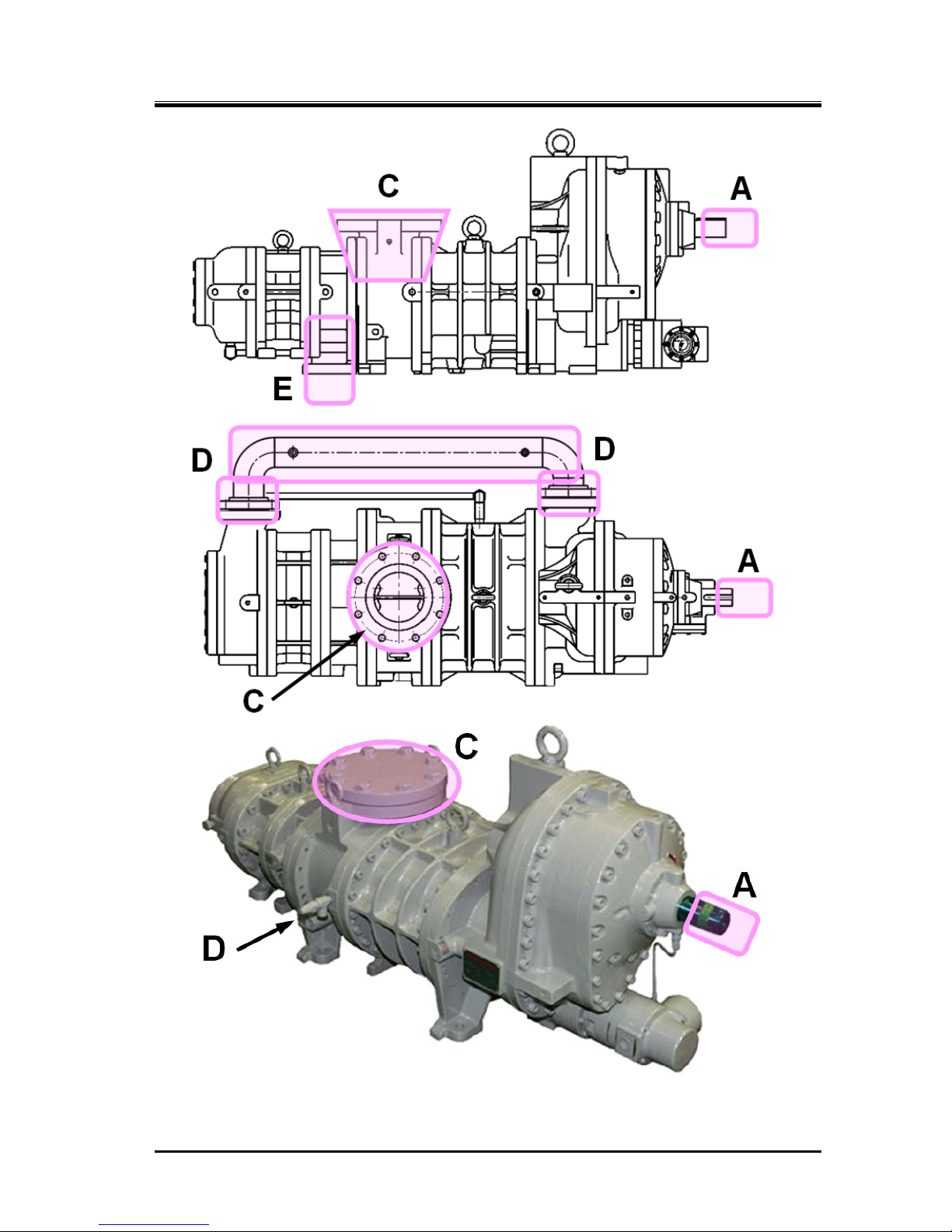
A
Motor and
compressor coupling
Refer to Figure 1-1
Caught in due to contact Install coupling cover
and prohibit opening.
Keep away.
Turn off motor main
power and control power,
and conduct
lockout/tagout.
B
Motor terminals
Electric shock caused by
contact with live wires or
electrical leakage
Keep away.
Do not open terminal
boxes.
Do not touch terminal
boxes.
Turn off motor main
power and control power,
and conduct
lockout/tagout.
C
Compressor
low-stage side
suction casing
Refer to Figure 1-1
Frostbite due to contact
Contact with or inhalation
of hazardous substances
generated by leakage of
refrigerant or the like
Keep away and do not
touch.
Wear protective gear.
Detect gas leakage.
Wear protective gear.
Work under room
temperature.
D
Compressor
intermediate piping
(low-stage discharge
port to high stage
suction port)
Refer to Figure 1-1
Burn injury due to contact
Contact with or inhalation
of hazardous substances
generated by leakage or
spout of refrigerant or the
like
Keep away and do not
touch
Wear protective gear
Gas leakage detection
Wear protective gear
Work in temperatures
below 40 °C
E
Compressor
high-stage side
discharge casing and
discharge piping
Refer to Figure 1-1
Burn injury due to contact
Contact with or inhalation
of hazardous substances
generated by leakage or
spout of refrigerant or the
like
Keep away and do not
touch.
Wear protective gear.
Detect gas leakage.
Wear protective gear.
Work at a temperature of
not higher than 40°C.
F
Check valves/service
valves and joints on
each section of the
package unit
Contact with or inhalation
of hazardous substances
generated by mishandling
or leakage
Frostbite or burn due to
contact
Sufficient ventilation
Indicate valve
open/close state.
Keep away and do not
touch.
Wear protective gear.
Sufficient ventilation
Wear protective gear.
Tagout for controlled
valve
G
Solenoid
valves/motor
operated valves on
each section of the
package unit
Electric shock caused by
contact with live wires or
electrical leakage
Pinched due to contact
with driving part
Install protective cover
on terminals, and
prohibit opening.
Keep away and do not
touch.
Wear protective gear.
Turn off each breaker and
the control power, and
conduct lockout/tagout.
Wear protective gear.
H
Electric components
in each section of the
package unit (oil
heater, protective
switch, etc.)
Electric shock caused by
contact with live wires or
electrical leakage
Pinched due to contact
with driving part
Install protective cover
on terminals, and
prohibit opening.
Keep away and do not
touch.
Wear protective gear.
Turn off each breaker and
the control power, and
conduct lockout/tagout.
Wear protective gear.
I
Package unit oil
drains
Contact with hazardous
substances generated by
leakage or spout
Burn caused by contact
with high-temperature
fluid
Sufficient ventilation
Keep away and do not
touch.
Wear protective gear.
Sufficient ventilation
Wear protective gear.
Work at a temperature of
not higher than 40°C.
J
Noises
Damage caused b y noise Wear protective gear.
—
2202L5JE-DA-C5-N_2015.05.
1. Safety
Compound 2-stage Screw Compressor 1.3 Residual Risks
1612LSC Speed Increaser Type
1-5
Figure 1-1 Locations of Hazardous Sources (compressor)
2202L5JE-DA-C5-N_2015.05.
1. Safety
Compound 2-stage Screw Compressor 1.4 Safety Devices
1612LSC Speed Increaser Type
1-6
1.4 Safety Devices
For safe use and protection of this product, make sure to attach safety devices to this product in
accordance with the regulations and the following instructions.
Safety devices cannot be kept in normal condition unless inspected and maintained at re gular intervals.
Their maintenance and inspection need to be performed as an important part of the
maintenance/inspection work project. Provide users of this product with necessary information on the
safety devices, for example, types of the safety devices, installation position, function, and inspection
method of safety related devices.
Check the safety devices after turning on the power and before operation of this
product. If they do not operate normally, immediately take repair or replace
safeties before starting this product.
1.4.1 Emergency Stop Button
Overview/Function/Purpose
The emergency stop buttons are used to stop the compressor operation immediately if an
emergency occurs in this product.
Installation Positions
On the control board and in the operation control room
Stop/Restoration Methods
The operating procedures for the emergency stop button, i.e., how to stop the operation and
restore the normal operating condition, must be clearly defined and the information provided to the
user of this product.
Inspection Method/Cycle
The emergency stop buttons must be tested before commissioning and must also be periodically
re-tested after that. The inspection procedures and the inspection interval for the emergency stop
button must be clearly defined and the information provided to the user of this product.
1.4.2 Breakers of Motor Main Power and Control Power
(with Lockout/Tagout Mechanism)
Overview/Function/Purpose
Turn off the main motor and control power, and if there is any possibility of danger during work
(especially during cleaning, maintenance, inspection, or troubleshooting), lockout/tagout devices
must be used on the breakers of the main motor and control powers to prevent injuries to workers in
case the power is turned on accidentally during work.
Methods of Performing and Releasing Lockout/Tagout
Make sure to clearly notify methods of performing and releasing lockout/tagout referring to the
regulations created by Occupational Safety & Health Administration (OSHA) or local governing
body.
Inspection Method/Cycle
The inspection procedures and the inspection interval for the lockout/tagout devices must be clearly
defined and the information provided to the user of this product.

2202L5JE-DA-C5-N_2015.05.
1. Safety
Compound 2-stage Screw Compressor 1.4 Safety Devices
1612LSC Speed Increaser Type
1-7
1.4.3 Compressor Protective Devices
Be sure to adjust the set values and check operation of the protective devices at
the commissioning.
Overview/Function/Purpose
These protective devices are used to protect this product.
Protecting from discharge temperature rise (DT)
This device stops the compressor operation when the discharge temperature of the
compressor exceeds the set value.
Install a temperature sensing port to the discharge pipe.
Protecting from oil temperature rise (OT)
This device stops the compressor operation when the oil temperature of the compressor
exceeds the set value.
Install a temperature sensing port to the package unit's oil supply pi pe (after the oil cooler).
Protecting from high pressure (HP)
This device stops the compressor operation when the discharge pressure abnormally rises
due to mishandling of the compressor or stoppage of cooling water supply to the condenser.
This device prevents explosion of the equipment and component s.
Install a pressure sensing port to the discharge pipe.
Protecting from intermediate pressure (IP)
This device controls the compressor appropriately when the intermediate pressure exceeds
the set value.
In some cases, this device stops the compressor operation.
Install a pressure output port to the package unit's intermediate gas pipe (or compressor's
intermediate gas pressure output port).
Protecting from suction pressure drop (LP)
This device stops the compressor operation when the suction pressure becomes below the
set value.
Install a pressure sensing port to the suction pipe.
Protecting from oil pressure (OP)
This device stops the compressor operation when lub ricating oil sup ply is not sufficient, the oil
filter is clogged, the refrigerant is mixed into the lubricating oil, and oil supply pressure
difference (from discharge pressure) becomes below the set value.
This device is to protect the compressor from wear and burnout.
Install a pressure sensing port to the package unit' s oil sup ply pipe (af ter the oil p ump) and the
discharge pipe.
Protecting from motor overcurrent (OCR)
This device controls the compressor appropriately when the current exceeds the set value. In
some cases, this device stops the compressor operation.
This device is normally installed in the compressor operation controller.
2202L5JE-DA-C5-N_2015.05.
1. Safety
Compound 2-stage Screw Compressor 1.4 Safety Devices
1612LSC Speed Increaser Type
1-8
Connection Positions and Settings
Specify the connection position and setting for each compressor protective device, and make sure
to provide users of this product with them.
Make sure that the set values do not exceed the operating limits shown in Chapter 2, section 2.3.2
and Table 2-2 of this manual.
Inspection Method/Cycle
Compressor protective devices require operation tests and confirmation of the settings calibration
before test run as well as at regular intervals.
Specify the inspection methods/intervals of the compressor protection devices, and make sure to
provide users of this product with such information.
In the operation test, check that alarms and protective devices operate norm ally
by using devices such as pressure tester. Do not operate the compressor with all
the valves closed, or in any other dangerous conditions.
If the protection from oil pressure (OP), high pressure (HP) activates, do not
restart operation until the cause of activation is removed.
2202L5JE-DA-C5-N_2015.05.
2 Compressor Specifications and Structure
Compound 2-stage Screw Compressor 2.1 Overview of the MYCOM 1612LSC Speed Increaser Type
1612LSC Speed Increaser Type
2-1
2 Compressor Specifications and Structure
2.1 Overview of the
Compound 2-stage
Screw Compressor 1612LSC Speed Increaser Type
The 1612LSC is a compound screw compressor integrating two stages of compressor
into a single body. The 1612LSC has been developed based on the LSC model of the 1612C Series
compressors —our most popular and long-selling products boasting the delivery of over 1000 units
worldwide since they were first put on the market— by adding the speed increaser gear system to
provide it with optimum performance for applications to ultra-cold and rapid freezing storage systems in
bonito and tuna fisheries.
Generally, screw compressors use oil injection to keep discharge temperature low during operation
without loss of volumetric efficiency even at high compression ratios, with singles-stage usage possible
even at evaporative temperatures near −40 °C.
However, for low-temperature regular usage, to improve KW/RT (the ratio of power consumption versus
cooling ability), a 2-stage compression method is used. To use standard-type screw compressors in a
2-stage compression method, at least two screw compressors must be combined so that there is a
high-stage and a low-stage, which requires multiple sets of machinery, power, and utilities, etc. to be
installed.
This 2-stage screw compressor combines these two units into one compound machine.
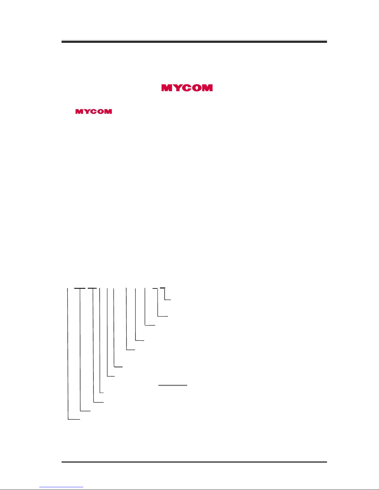
2.2 Model Designation of the Compressor
This manual describes the 1612LSC-*B*-52, -62, -53, -63, and -54 speed increaser type models.
The meaning of the type designation stamped on the nameplate of the compressor MODEL column is
as follows.
*1612LSC-*B*-52(62, 53, 63, 54)
2, 3 or 4
:Speed increaser gear ratio specification
( refer to the specifications table on the next page.)
5:Power frequency 50Hz (6:60Hz)
Vi of the high-stage discharge port specification (volume ratio),
as standard L port or M port
Means the machine (low-stage) booster
Vi of the low-stage discharge port specification (volume ratio),
as standard L port or M port
Means two-stage machine single unit
Shows the specifications of the high-stage rotor length,
only S for accelerator
speed increaser type
Shows the specifications of the low-stage rotor length, only L for speed increaser type
High-stage rotor
diameter of 125
Low-stage rotor diameter of 160
Means the working fluid
(Example: N = ammonia, F = Freon, P = Propane , HE = helium)
2202L5JE-DA-C5-N_2015.05.
2 Compressor Specifications and Structure
Compound 2-stage Screw Compressor 2.3 Compressor Specifications
1612LSC Speed Increaser Type
2-2
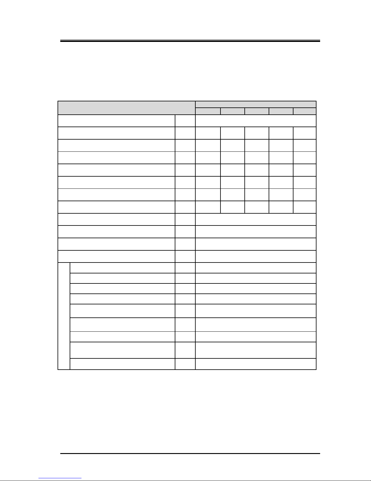
2.3 Compressor Specifications
2.3.1 Standard Specifications
Table 2-1 1612LSC Speed Increaser Type Screw Compressor Specifications
Item
1612LSC Speed Increaser type
52 62 53 63 54
Product mass kg 560
Applied frequency Hz 50 60 50 60 50
Motor Poles - 4P 4P 2P 2P 2P
Speed increaser gear ratio - 1.809 1.809 1.220 1.220 1.472
Male rotor rotational speed min
-1
2610 3150 3610 4350 4350
Female rotor rotational speed min
-1
1740 2100 2407 2900 2900
Low-stage swept volume m3/h 551 665 762 918 918
High-stage swept volume m3/h 174 210 241 290 290
Applied refrigerant - Ammonia, Hydrofluorocarbon, other
Design pressure MPa 2.6
Capacity control range (Actual load) % 10 to 100
Rotation direction - Crockwise viewed from motor
Connection pipe size
Suction flange low-stage - MYCOM 125A (5″)
Discharge flange low-stage
- MYCOM 80A (3″)
Suction flange high-stage - MYCOM 80A (3″)
Discharge flange high-stage
-
MYCOM 65A (2½″)
Journal lubricating oil supply
(low-stage)
- Rc1/2
Journal lubricating oil supply
(high-stage)
- Rc3/8
Oil injection lubricating oil supply
- Rc3/8
Mechanical seal and speed increaser
gear lubricating oil supply
- Rc1/4
Capacity control - Load: Rc1/4, Unload: Rc3/8
In this manual unless otherwise noted, pressure units MPa represents the gauge pressure.
For usage temperature ranges and pressure ranges, refer to Section2.3.2 “Operation Limits”.
2202L5JE-DA-C5-N_2015.05.
2 Compressor Specifications and Structure
Compound 2-stage Screw Compressor 2.3 Compressor Specifications
1612LSC Speed Increaser Type
2-3
2.3.2 Operation Limits
Table 2-2 Operation Limits of 1612LSC Speed Increaser type
Items Operation Limits
Maximum discharge pressure MPa 1.96
Minimum suction pressure MPa −0.080
Maximum intermediate pressure MPa 0.588
Minimum intermediate pressure - > Suction pressure
Oil supply pressure
・ Maximum journal lubrication pressure MPa Discharge pressure + 0.39
・ Minimum journal lubrication pressure
MPa
Discharge pressure +0.049 and
Suction pressure +0.49
・ Minimum oil injection pressure MPa Suction pressure +0.49
Maximum Suction temperature °C 85
Minimum suction temperature °C −60
Maximum low-stage discharge temperature °C 90
Maximum high-stage discharge temperature °C 100
Maximum oil supply temperature °C 60
Minimum oil supply temperature °C 30
Maximum M (mail) rotor rotation speed min-1 4500
Minimum M (male) rotor rotation speed min-1 1450
Note : Unless otherwise noted, the pressure unit MPa represents the gauge pressure in this manual.
If operation at a indicated load of less than 30 % of capacity control is continued
for a long time except when starting up the machine, abnormal noises or
vibration may occur, so avoid doing so.
Repeating startup or shutdown operations in a short period of time is detrimental
for the starter and the motor as well as for the compressor itself. Refer to the
documentation of each device for the starting and stopping limitations of the
starter and the motor. After stopping the compressor, wait 15 minutes or more
before performing the next startup procedure.
2202L5JE-DA-C5-N_2015.05.
2 Compressor Specifications and Structure
Compound 2-stage Screw Compressor 2.3 Compressor Specifications
1612LSC Speed Increaser Type
2-4
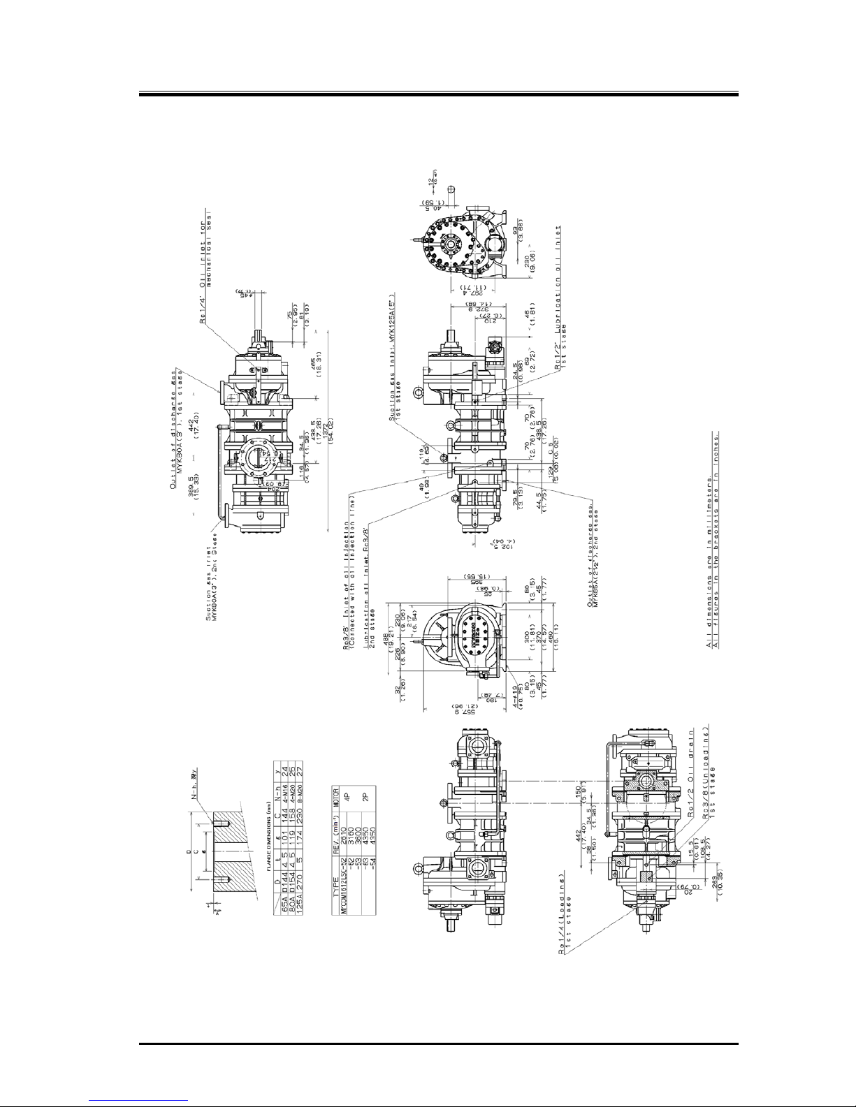
2.3.3 Outer Dimensions
Figure 2-1 1612LSC Speed Increaser Type Outer Dimensions
2202L5JE-DA-C5-N_2015.05.
2 Compressor Specifications and Structure
Compound 2-stage Screw Compressor 2.4 Structure of Compressor
1612LSC Speed Increaser Type
2-5
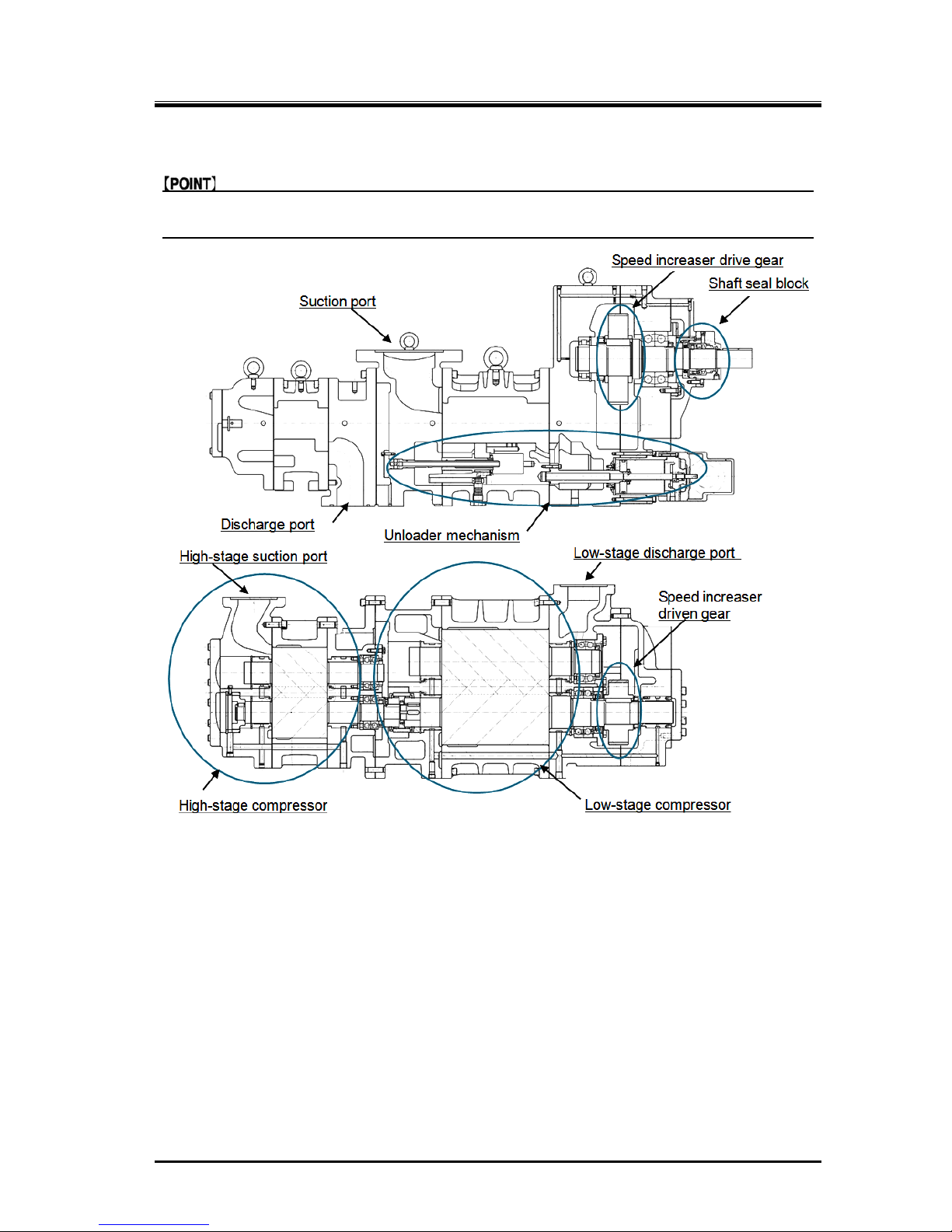
2.4 Structure of Compressor
For the names and locations of the compressor components, refer to Section 7.1 “Development
Views, Assembly Sectional Views” and Section 7.2 “Parts Configuration Table” in this manual.
Figure 2-2 1612LSC Speed Increaser Type Sectional View
The 162LSC screw compressor consists of the following four main blocks: the shaft seal block which
prevents leakage of the refrigerant gas and lubricating oil from the compressor’s axis; the speed
increaser gear casing assembly which houses the drive and driven gears for increasing the rotating
speed of the electric motor’s output shaft; the low-stage compressor block which pressurizes
(pre-compresses) the gaseous working fluid coming from the freezing storage system; and the
high-stage compressor block which further compresses the working fluid gas pressurized by the
low-stage compressor before discharging it into the freezing storage system.
Like with the 1612**C Series direct drive type screw compressors, the 1612LSC speed increaser type
screw compressors has the capacity control (unloading) mechanism which works for reducing the
machine load at the time of the start of operation and keeping constant the load which would otherwise
vary during operation of the freezing storage system.
Inside each of the low-stage and high-stage compressor casings, there is a pair of screw rotors
meshing each other and supported by bearings at both ends. One of each pair is the male rotor having
four convex-shaped screw lobes and the other is the female rotor having six concave-shaped screw
lobes. In combination, they perform the work of compressing the refrigerant gas through the process
described in the next section.

2202L5JE-DA-C5-N_2015.05.
2 Compressor Specifications and Structure
Compound 2-stage Screw Compressor 2.5 Mechanisms
1612LSC Speed Increaser Type
2-6
2.5 Mechanisms
2.5.1 Basics of the Screw Compressor
The screw compressor is a positive displacement rotary comp ressor.
As shown in Figure 2-3 Compressor Mechanism, the refrigerant (gas) is continuously compressed by
changing the volume between the casing and the male and female meshed screw rotors, which have
different profiles.
The rotor with 4 protruding lobe sections is called the M rotor (male rotor), and the rotor with 6 lobe
depressions is called the F rotor (female rotor). Throughout this manual they are referred to as the M
rotor and F rotor.
The compressor M rotor shaft is driven by the two-pole or four-pol e motor via the spe ed i ncreaser ge ar.
Figure 2-3 Compressor Mechanism
2.5.2 Suction Process
As shown in Figure 2-4 Suction Process, the rotors’ different profiles mesh together. Also the volume
enclosed between the M and F rotor lobes and compressor casing increa ses from the suction side as
the rotors turn.
As rotations continue, at a certain point the volume reaches it s maximum, the rotors start to tra p the gas
between the lobes and compressor casing thereby isolating the gas from the suction port.
Figure 2-4 Suction Process
2202L5JE-DA-C5-N_2015.05.
2 Compressor Specifications and Structure
Compound 2-stage Screw Compressor 2.5 Mechanisms
1612LSC Speed Increaser Type
2-7
2.5.3 Compression Process
As the rotors further rotate, the sealing line between them moves toward the discharge side and the
volume between the rotor lobes decreases and compresses the trapped gas.
Figure 2-5 Compression Process Figure 2-6 Discharge Process
2.5.4 Discharge Process
Through the compression process, the volume between rotor lobes decreases to a predetermined
value at the discharge port.
Following rotor rotation, the compressed refrigerant gas is pushed out of the discharge port.
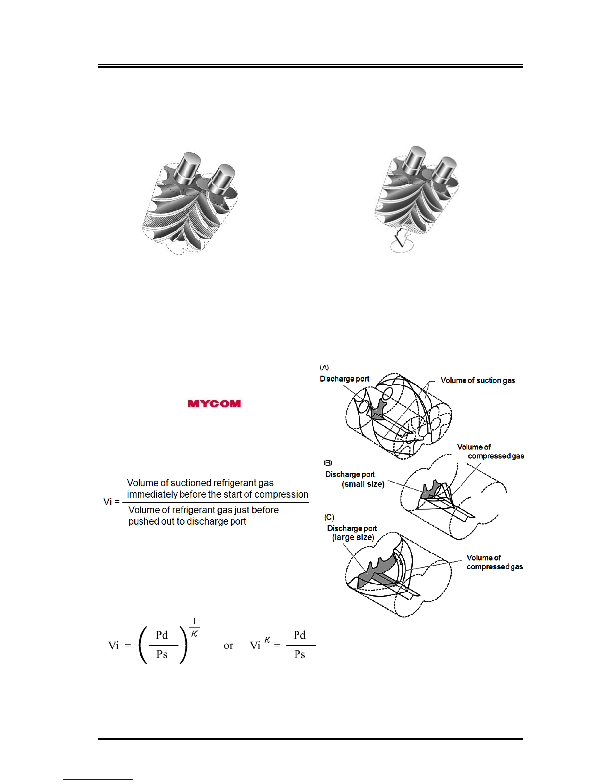
2.5.5 About Volume Ratio (Vi)
Volume ratios (Vi) of C-series screw
compressors are indicated in performance tables
or catalogs by using port symbols L and M.
The volume ratio represented by each symbol is
as follows:
L=2.63, M=3.65.
Which volume ratio (L or M) should be used is
decided according to operating conditions. If the
compressor is used with a volume ratio that does
not match operating conditions, operation will go
inefficiently wasting the power.
The relationship between volume ratios and
generally used compression ratios is as follows:
(Vi)
κ
= πi = Pd/Ps κ= Cp/Cv of refrigerant gas
Vi = designed volume ratio πi = designed compression ratio
The constant of the refrigerant gas also a factor, and the Vi value for the compression ratio will change
according to the refrigerant gas used.
Figure 2-7 Volume Ratio Explanation
2202L5JE-DA-C5-N_2015.05.
2 Compressor Specifications and Structure
Compound 2-stage Screw Compressor 2.5 Mechanisms
1612LSC Speed Increaser Type
2-8
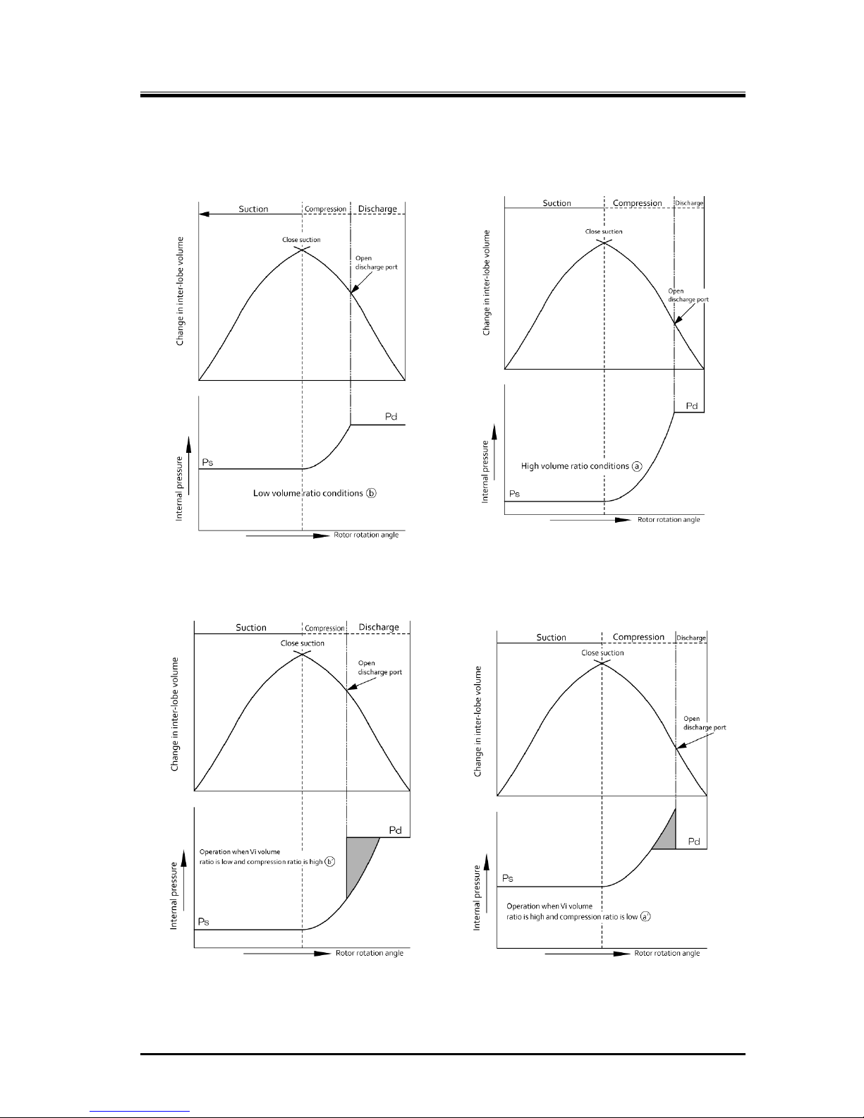
(A) When Vi matches operation conditions
The required compression ratio and Vi are both low The required compression ratio and Vi are both high
(B) When Vi does not match operation conditions
Vi is too low compared to
the required compression ratio
Vi is too high compared to
the required compression ratio
Figure 2-8 Relationship between volume ratio (Vi) and operation conditions
2202L5JE-DA-C5-N_2015.05.
2 Compressor Specifications and Structure
Compound 2-stage Screw Compressor 2.5 Mechanisms
1612LSC Speed Increaser Type
2-9
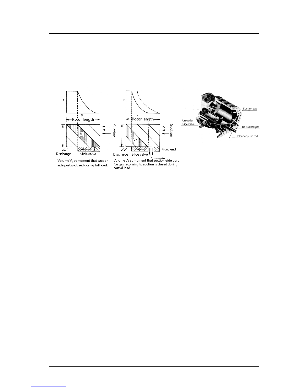
2.5.6 Capacity Control Mechanism
The capacity control structure involves the moving of a slide valve, bypassing suction gas just before
compression on the suction side, which shortens the portion of the rotor used for compression. The
slide valve is at the bottom of the casing where the rotors mesh together, and is constructed to move
parallel to the rotor’s axis. This movement is changed by a cam mechanism into rotation movement,
and as the position (capacity control ratio) is indicated externally, the electrical resistance value
changes to provide feedback to the automatic control circuit.
Figure 2-9 Capacity Control Mechanism
The 1612LSC speed increaser type has capacity control on the lo w-stage block only.
2.5.7 Bearings and Balance Piston
For the load created on the rotor perpendicular to the axle, a white metal-lined sleeve-type bearing is
used. The bearing uses surface fitted ball bearings with angular contact for loads along the axis
direction.
In particular, axial load for the M rotor, which has one type of helical gear, is comparatively larger than
that of the F rotor because of the thrust load from discharge pressure. This load for the M rotor is
reduced by the use of a thrust bearing, along with a balance piston providing opposing hydraulic
pressure.
2.5.8 Shaft Seal
To prevent refrigerant gas and oil leakage, a reliable mechanical seal assembly is used for the shaft
seal of the speed increaser gear spindle.
Mechanical seal assembly is mainly composed of "rotating ring" installed on the rotor shaft and
"stationary ring" installed in the seal cover. Rotating ring rotates with the shaft, and slides each other
with the stationary ring while maintaining a micron class gap. The sliding each other place is called as
the sliding surface.
As an example, for the BBSE (Balanced Bellows Single Seal)-type, which is a standard seal currently in
use, the fixed ring (mating ring) is cast iron, and the rotating ring is carbon, with an O-ring for the
packing.
Figure 2-10 Slide Valve in the
Rotor Casing
2202L5JE-DA-C5-N_2015.05.
2 Compressor Specifications and Structure
Compound 2-stage Screw Compressor 2.6 Gas and Oil Flow
1612LSC Speed Increaser Type
2-10
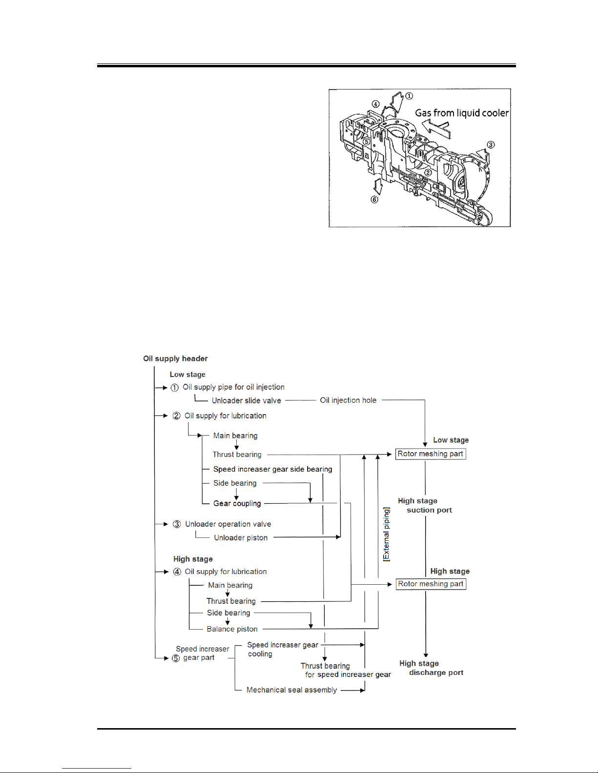
2.6 Gas and Oil Flow
The screw compressor’s compression process is
described earlier in this manual.
Gas for the compound speed increaser type 1612LSC
compressor passes from the evaporator and through
the suction strainer and check valve, and is sucked
into the center part of the compressor ①, and it is
compressed at the low-stage ② .Then the
compressed gas is discharged at ③. ③ and ④ are
connected by piping through which gas used for super
cooling is mixed in from the liquid cooler.
Lubricating oil injected at the low-stage is, while kept
mixed with gas, suctioned from ④ into the high-stage.
After being compressed at ⑤, the gas mixed with
lubricating oil is discharged from ⑥ to the oil separator, and then sent to the condenser.
The oil is cooled even without intermediate gas cooling, so the high-stage discharge temperature can
be maintained at below 90 °C.
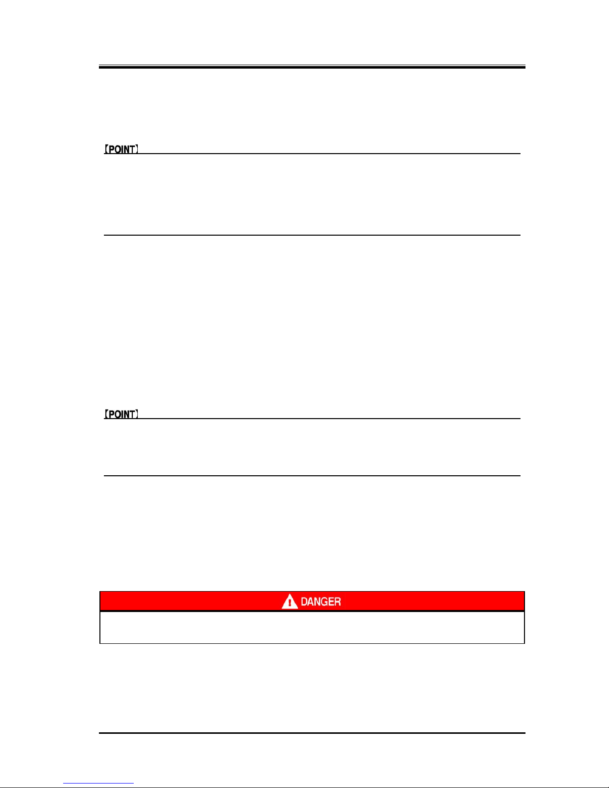
Oil Supply Route
Lubricating oil is split into 4 flows as shown in Figure 2-12, and after providing lubrication, it is
mixed with discharge gas and leaves the compressor. In standard configurations, oil injection is not
performed at the high-stage.
Figure 2-12
1612LSC Speed Increas er Type Oil Supply Route
Figure 2-11 Gas Flow
2202L5JE-DA-C5-N_2015.05.
3 Installation
Compound 2stage Screw Compressor 3.1 General Precautions for Installation
1612LSC Speed Increaser Type
3-1
3 Installation
3.1 General Precautions for Installation
This chapter is based on the assumption that the compressor is installed to a standard
refrigeration/cold storage package unit.
If the package unit is not a standard refrigeration/cold storage package unit, prepare an
installation procedure manual referring to this chapter and considering safety precautions, before
installing the compressor.
If there are any questions, please contact our local sales offices or service centers.
In some cases, it may be required that installation is performed by qualified personnel.
Make sure that the work is performed by qualified personnel in compliance with local laws and
ordinances.
Read this chapter and related documents, and fully understand their contents before
performing installation.
Electrical work must be performed only by electrical engineers .
3.2 Installation Works
3.2.1 Unpacking
Check that there are no abnormalities such as damage on the compressor.
If there are abnormalities or deficient parts on the compressor, please contact our local sales
offices or service centers.
Unnecessary packaging materials should be discarded according to the laws and ordinances, or
your company’s rules.
3.2.2 Storage
If you need to store the compressor before installation, perform the followings:
Store it indoors.
Seal nitrogen gas in the compressor. (Pressure: approximately 0.15 MPa)
3.2.3 Transportation
Dropping of the lifted compressor may cause death or serious injury to the
worker. Do not allow anyone to be under the lifted compressor.
1. To lift the compressor, use lifting equipment with sufficient load capacity for the mass of the
compressor and appropriate lifting slings having proof load of more than the mass of compressor.
2. Secure sufficient space for safe lifting.
2202L5JE-DA-C5-N_2015.05.
3 Installation
Compound 2stage Screw Compressor 3.2 Installation Works
1612LSC Speed Increaser Type
3-2
3. Check the wire ropes before use. Thoroughly check the wire ropes for problems such as kinks,
knots, and broken strands. Do not start lifting unless the wire ropes have been verified and have no
problems. If you cannot make a correct evaluation or judgment, entrust an expert to inspect.
4. To lift the compressor, attach the wire ropes to the attached eyebolts using appropriate shackles
and hooks. The eyebolts are only used for lifting the compressor. Do not use the eyebolts to lift the
compressor with any attached apparatus.
The compressor eyebolts must not be used to lift the p ackage unit. To lift the package
unit, use the lifting chains on the compressor unit base periphery or other lifting
devices provided on the compressor unit base.
5. Check the transportation route for any obstacles in consideration of the compressor size.
6. Before lifting, check that the hook is located above the gravity center of the compressor.
7. Instruct all workers to move from near the work site before lifting.
8. Before lifting the compressor, alert all workers on the site of possible dangers of the lifting process
by signal (such as calling at the beginning of the work or making a signal by hand). Do not lift the
compressor unless the signals are completely understood by all personnel working together.
9. Slowly windup the wire ropes until shortly before the compressor leaves the ground.
10. Then, wind up the wire ropes a little further until the compressor is slightly away from the ground
and check that the compressor is balanced. If the compressor is inclined, return the compressor to
the ground and correct the inclination by adjusting the wire ropes. Then, restart the lifting operation.
11. Make sure to wind up the compressor slowly. Lifting it too quickly may damage the lifting equipment
including the wire ropes or part of the compressor.
12. When lifting the compressor, check the state of the wire ropes and lifting equipment. Check that the
compressor is not inclined.
13. When moving the lifted compressor, always use guiding ropes.
14. When moving the compressor, turn away workers from the movement direction and check safety.
15. Do not lift the compressor above any safety aisles unless absolutely necessary.
16. Do not put the compressor in a safety aisle. Always keep the safety aisle free of obstacles.
17. Remove any obstacles before putting down the compressor on the ground. The compressor should
not be inclined or unstable.
18. Before putting down the compressor on the ground, announce to the workers around the working
area.
19. When lowering the compressor onto two or more blocks, align the tops of blocks so that the
compressor becomes stable horizontally on them.
20. Lower the compressor slowly so that it does not get damaged due to impact.
 Loading...