

C OMBI OVEN
INSTALLATION MANUAL

INDICE
1. INTRODUCTION ............................................................................................................. 6
2. TECHNICAL CHARACTERISTICS .................................................................................. 7
2.1 Main characteristics MyChef S ............................................................................. 7
2.2 Main characteristics MyChef L ............................................................................. 7
3. GENERAL SAFETY AND ACCIDENT PREVENTION REGULATIONS............................ 8
3.1 Personnel responsible for using the equipment .................................................. 8
3.2 Electrical hazard ..................................................................................................... 8
3.3 Thermal hazard ...................................................................................................... 8
3.4 Corrosion hazard.................................................................................................... 8
4. RECEPTION, TRANSPORT AND POSITIONING .......................................................... 10
4.1 Reception .............................................................................................................. 10
4.2 Transport .............................................................................................................. 10
4.3 Positioning ............................................................................................................ 10
5. INSTALATION .............................................................................................................. 12
5.1 Electrical connection ........................................................................................... 12
5.1.1 Three phase connection 400V 3L+N .......................................................... 14
5.1.2 Three phase 230V 3L ................................................................................... 15
5.1.3 Single phase 230V L+N ................................................................................ 17
5.2 Water connection ................................................................................................. 19
5.2.1 Water input .................................................................................................... 19
5.2.2 Drain .............................................................................................................. 19
5.3 Vapour condensation hood ................................................................................. 19
6. GENERAL ELECTRICAL DIAGRAM.............................................................................. 21
6.1 Power MyChef S ................................................................................................... 21
6.2 Relés MyChef L .................................................................................................... 22
6.3 Control MyChef S and MyChef L ......................................................................... 23
5

1. INTRODUCTION
Before carrying out any intervention or use of the equipment, it is necessary
to read this manual carefully and completely.
The manufacturer shall disclaim any liability for problems caused by
improper installation, modification, use or improper maintenance.
This manual has been carefully prepared and checked to provide reliable and helpful
information for proper installation, use and maintenance that will ensure proper
operation and prolong the life of the furnace. This manual is divided into two parts, the
first part dedicated to the installation of the equipment at the working point, and the
second part focused on cleaning and maintenance of the oven.
The manufacturer disclaims any implied or explicit liability for any errors or omissions
it may contain.
- The furnace may not be used by personnel who have not received any kind of
training, and who do not have the necessary skills or experience for the correct
operation of the equipment. Do not allow children to use or play with the
computer.
- The owner of the equipment has the obligation to have this manual read to the
personnel in charge of its use and maintenance, and to keep this manual in a
safe place so that it can be used by all users of the equipment and for future
reference. If the equipment is sold to other people, this manual must be given
to them.
- This oven may only be used for the purpose for which it was designed, i. e.
cooking, heating, regenerating or dehydrating foodstuffs. Any other use may be
hazardous and may result in personal injury and damage to property.
- The equipment is shipped from the factory once it has been calibrated and
passed rigorous quality and safety tests to ensure its correct operation.
6
4GN 1/1
6GN 2/3
6GN 1/1
6GN 1/1 T
9GN 1/1
External dimensions
(Width x Depth x
Height)
520 x 800 x
662mm
520 x 623 x
662mm
520 x 800 x
662mm
760 x 595 x
662mm
520 x 800 x
822mm
Capacity
4 GN 1/1
40mm
6 GN 2/3
40mm
6 GN 1/1
40mm
6 GN 2/3
40mm
10GN 1/1
40mm
Power (1L+N)
2,9/5,6kW
2,9/5,6kW
- - -
Power (3L, 3L+N)
5,6kW
5,6kW
7kW
7kW
10,4kW
Distance between
trays
62mm
54mm
54mm
54mm
54mm
Meals/day
20-80
20-80
30-100
30-100
50-150
Currant (1L+N)
13/24A
13/24A
- - -
Current (3L, 3L+N)
12A
12A
15A
15A
23A
Cable section
2.5mm2
2.5mm2
2.5mm2
2.5mm2
2.5mm2
6GN 1/1
6GN 2/1
10GN 1/1
10GN 2/1
External dimensions
(Width x Depth x Height)
760 x 700 x
822mm
760 x 950 x
822mm
760 x 700 x
1122mm
760 x 950 x
1122mm
Capacity
6 GN 2/3
40mm
6 GN 1/1
40mm
6 GN 2/3
40mm
10GN 1/1
40mm
Power (1L+N)
10.7kW
17.2kW
18.4kW
34.4kW
Power (3L, 3L+N)
73mm
73mm
73mm
73mm
Distance between trays
40-110
60-180
80-160
150-300
Meals/day
16A
25A
27A
50A
Currant (1L+N)
2.5mm2
4mm2
4mm2
10mm2
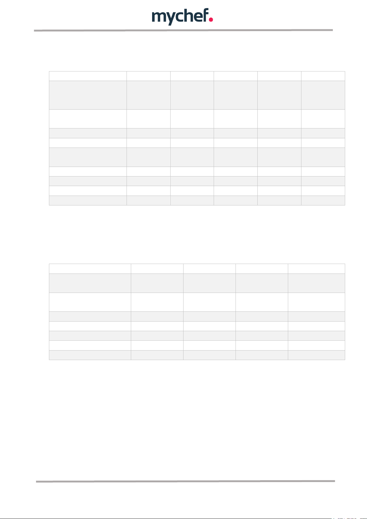
2. TECHNICAL CHARACTERISTICS
2.1 Main characteristics MyChef S
Table 1: Main features of MyChef S ovens.
The maximum recommended load of food per GN 1/1 40mm tray is 3.5 Kg and 2Kg for
GN 2/3 trays.
2.2 Main characteristics MyChef L
Table 2: Main features of MyChef L ovens.
The maximum recommended load of food per GN 1/1 65mm tray is 5 Kg and 3.5Kg for
GN 2/3 trays.
7
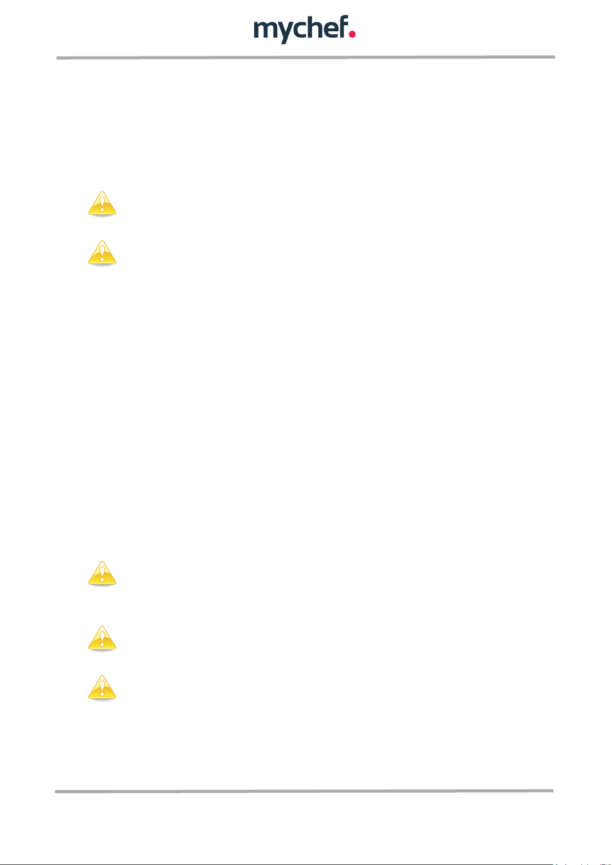
3. GENERAL SAFETY AND ACCIDENT PREVENTION REGULATIONS
Personnel performing any action on the furnace, whether it be use, cleaning,
installation, handling, etc. must be familiar with the safety regulations and
instructions for use.
Do not allow unauthorized personnel to use, handle, or clean equipment.
Keep ventilation openings clear of obstacles. Do not install the equipment in
the vicinity of flammable products. Avoid positioning the oven near sources
of heat such as stoves, irons, fryers, etc. Check the safety distances in
chapter ¡Error! No se encuentra el origen de la referencia..
DANGER OF ACCIDENT! Use caution when using food containers in the oven
when the top tray is 160 cm or higher. There is a risk of injury from the hot
contents of GN trays.
While the furnace is in operation, avoid touching metal parts and the glass of
the door as they can exceed 60°C. Touch only the handle and control panel.
3.1 Personnel responsible for using the equipment
Use of the equipment is reserved for trained personnel.
3.2 Electrical hazard
Work on the power supply and access to live parts is permitted only by qualified
personnel and at their own risk. In any case, this access must be done with the
equipment disconnected from the mains supply.
If the appliance is placed on a trolley or on tables that have some mobility, do not allow
it to move while connected to the power source to avoid possible damage to the wiring,
drain pipes or water inlet pipes. In case you want to move or change the position of the
unit, disconnect the cables and drains and water pipes.
3.3 Thermal hazard
When the appliance is in operation, open the door slowly and carefully to avoid possible
burns from the steam or hot air that may come out of the cooking chamber.
3.4 Corrosion hazard
When using cleaning products, special care and appropriate safety measures should be
taken to handle these products. Always read the safety data sheets of the different
chemicals before using them and follow their instructions for use. These products, in
8

Use MyCare cleanduo in ovens equipped with automatic washing system,
and DA21 in ovens with semi-automatic washing system. Use of other
products voids warranty.
contact with any part of the body, are abrasive and can produce skin and eye irritations
and caustications.
During the cleaning process of the combi steamer and in case of aerosol or mist
formation during handling of the cleaning products, wear a facemask with particle filter
type P2 / P3, panoramic splash glasses and/or spray masks and chemical protective
gloves.
MyCare cleanduo and DA21 cleaning products have been specially formulated for the
correct cleaning and protection of MyChef ovens with automatic and semi-automatic
washing respectively. Both products contain, in addition to detergent, polish for a
perfect finish. The use of these detergents in MyChef ovens is mandatory.
9

4. RECEPTION, TRANSPORT AND POSITIONING
Before carrying out the installation, the dimensions of the site where the equipment is
to be installed and the electrical and water connections must be checked, and it must
be verified that they are within the parameters detailed in the installation sheet.
4.1 Reception
Once the furnace has been received, check that the model purchased corresponds to
the order.
Check that the packaging is undamaged during transport and that there are no missing
parts or pieces of equipment. If any anomalies or problems are detected, please
contact your dealer immediately.
4.2 Transport
The equipment must be transported in its original packaging to the place closest to the
point of installation to avoid damage as much as possible. It is recommended that the
original packaging be stored until the equipment is properly installed and operating.
To move the equipment and place it in your workspace, consider the following
observations:
- The dimensions of the different models to be taken into account when passing
through narrow spaces (passageways, doors, narrow spaces). See Table 1 and
Table 2.
- The manipulation must be done with the necessary personnel to move the load
of the furniture taking into account the regulations in force regarding work
safety at the place of installation.
- During the movement of the oven, it must always be in a vertical position. It
must be lifted perpendicular to the ground and transported parallel to it.
- Make sure that during transport it does not tip over and does not hit any
objects.
4.3 Positioning
- Place the oven at a convenient distance from the wall to make the electrical and
water connections. There must be a minimum separation from the parts of the
furnace so that it can be properly ventilated and cooled. This minimum distance
is:
o 50mm on the left and right sides
o 100mm from the rear part
o 500mm at the top
10

For the installation of stacked MyChef ovens, follow the instructions
supplied with the corresponding stacking kit.
500m
100mm
50mm
1000m
50mm
- The unit must be placed on a MyChef support table or wall mount.
- If there are heat sources near the equipment (burners, grills, grill, fryer, etc.),
these must be at a distance of more than 1 metre.
- Once it is placed in the workspace, check that it is level.
- Never block the underside of the front water collector.
Figure 1: Example of suitable installation location.
11

5. INSTALATION
Connection to an equipotential bonding system ensures additional safety in
the event of simultaneous ground fault and differential failure.
Observe the applicable regulations for connecting the equipment to the lowvoltage mains supply.
5.1 Electrical connection
Check that the voltage at the point where the furnace is to be connected matches the
operating voltage of the equipment.
Before carrying out any electrical work, make sure that there is no electric current at the
equipment connection point.
The equipment must be connected to the mains by means of an omnipolar cut-off
switch and with a contact opening distance of more than 3 mm. Also install a class A
differential device and overcurrent protection.
Always guarantee an efficient earthing system.
Connect the equipment to an equipotential bonding system using the specially
designed contact for this purpose (see equipotential sign on the lower left side of the
equipment). In the case of two stacked equipment, both must be connected to the
equipotential bonding system.
Wiring and other safety devices used for electrical installation must have the
appropriate cross-section for the equipment in question.
Before starting the electrical installation, verify that the electrical requirements of the
furnace and mains supply are the same.
For correct connection after positioning, you will need a cable with a length that allows
you to reach the connection point plus about 20cm, to make the connection on the
back of the equipment. Remove the rear plate from the equipment. Insert the cable
through the cable gland in the lower left-hand side of the furnace (see rear panel).
Some MyChef ovens can be connected to different voltages and configurations at the
time of installation. To make the correct connection, use the terminal blocks supplied
with the equipment according to the instructions in the following subchapters. These
terminal strips are located between contacts 4 and 5 of the terminal block.
12

Figure 2: Terminal junction strips.
Figure 3: Entrada de cable y bornero.
Never connect a phase to neutral or ground. Check that the installation
voltages correspond to those of the equipment.
Check, once the connection has been made, that no cable is loose and they are all
firmly fastened. Also secure the cable gland.
The following subchapters show the three types of possible connections for MyChef
ovens.
13

5.1.1 Three phase connection 400V 3L+N
Figure 4: Three phase 400V 3L+N.
Figure 5: Three phase 400V 3L+N.
Color
Cable
Connector
■
Brown
L1
1 ■ Black
L2
2 ■ Grey
L3
3
■
Blue
Neutral
4
■
Green-yellow
Ground
Ground
Table 3: Three phase cable 400V 3L+N.
14

Figure 6: Three phase 230V 3L.
Figure 7: Three phase 230V 3L.
Color
Cable
Connector
■
Brown
L1
1
■
Black
L2
2,3
■
Grey
L3
4 ■ Green-yellow
Ground
Ground
5.1.2 Three phase 230V 3L
5.1.2.1 MyChef
Table 4: Three phase cable 230V 3L MyChef.
To connect terminal block positions 2-3, use the connecting plate supplied with your
MyChef oven.
15

5.1.2.2 MyChef L
Figure 8: Three phase 230V 3L.
Figure 9: Three phase 230V 3L.
Cable
Cable
Connector
■
Brown
L1
1 ■ Black
L2
2,4
■
Grey
L3
3
■
Green-yellow
Ground
Ground
Table 5: Three phase cable 230V 3L MyChef L.
In this type of connection, the triangular convection resistors must be rewired (Delta).
Figure 10: Star and triangle (Delta) connections
16

Figure 11: Single phase half power.
Figure 12 Single phase half power.
Figure 13: Single phase full power
Figure 14: Single phase full power.
5.1.3 Single phase 230V L+N
This type of connection is only valid for MyChef ovens S 4GN1/1 and MyChef S
6GN2/3.
17

Color
Cable
Connector
■
Brown
L1
1,2,31
■
Blue
Neutral
4 ■ Green-yellow
Ground
Ground
1
Table 6: Single phase cable 230V L+N.
Use the connecting plates supplied with your MyChef furnace to connect positions 1-2
and 2-3 of the terminal block.
Connection in position 3 is made at full power.
18

If it is a new installation, the water should be allowed to run until the
connection is completely purified. This operation must be repeated each
time work or repairs are carried out on the water supply to the furnace
A
B
5.2 Water connection
5.2.1 Water input
Cold water (max. 30°C) ¾’’ from 150 to 400 kPa of dynamic flow pressure.
Potable quality water with the following characteristics:
- Hardness between 3º y 6º FH
- PH between 6,5 y 8,5
- Chlorides lower than 30ppm
Use of water softener and filter is mandatory.
The furnace has two dedicated water inlets on the back of the furnace, one for soft
water (A) used for steam generation and one for untreated water (B) for self-cleaning
processes.
Figure 15: Soft (A) and untreated (B) water inlets.
5.2.2 Drain
For proper operation of the steam system of the furnace, the equipment must be
connected to a drainage system of 40mm nominal diameter (DN40) through a heatresistant pipe. The MyChef oven incorporates an internal odour blocking system that
can come from the drainpipe.
For correct operation, keep in mind that the pipe must have a constant minimum slope
of 5º.
5.3 Vapour condensation hood
Refer to the installation manual supplied with the vapour condensing hood for
installation.
19

The steam condensing hood is optional equipment. The hood can be
installed after the furnace has been installed.
20

6. GENERAL ELECTRICAL DIAGRAM
6.1 Power MyChef S
Figure 16: Electrical drawing MyChef S.
21

6.2 Relés MyChef L
Figure 17: Electrical drawing MyChef L.
22

6.3 Control MyChef S and MyChef L
Figure 18: Human interface.
23
 Loading...