

Mychef FSSB22G2, iSENSOR, TTSB06G2, FSSB2UG2, FSSB2LG2 Installation, Operation And Maintenance Manual
...
INSTALLATION, OPERATION AND MAINTENANCE MANUAL
iSENSOR

1
Index
1. INTRODUCTION ..................................................................................................................... 3
2. TECHNICAL CHARACTERISTICS .............................................................................................. 3
2.1 Functional equipment ................................................................................................... 3
2.2 Constructive features .................................................................................................... 3
2.3 General tabletop model sizes ........................................................................................ 4
2.4 General floor standing model sizes ............................................................................... 5
3. GENERAL SAFETY AND ACCIDENT PREVENTION REGULATIONS ........................................... 6
3.1 Operating personnel of the machine ............................................................................ 6
Personnel must be familiar with the safety regulations and instructions for use. ................... 6
3.2 Electrical hazard ............................................................................................................ 6
3.3 Thermal hazard ............................................................................................................. 6
3.4 Hazard arising from the use of gas ................................................................................ 6
This machine is not designed for the use of Oxygen O2 or other flammable gases. .................... 6
4. INSTALLATION ....................................................................................................................... 6
5. CONTROL PANEL.................................................................................................................... 7
6. CALIBRATION ......................................................................................................................... 8
6.1 Self Calibration system SCS ........................................................................................... 8
7. OPERATION ........................................................................................................................... 9
7.1 Powering and switching on the machine ...................................................................... 9
7.2 Inert gas injection ........................................................................................................ 10
7.3 Operating modes ......................................................................................................... 10
7.3.1 Automatic mode .................................................................................................. 10
7.3.2 Manual mode ...................................................................................................... 11
7.3.3 Autoclean ............................................................................................................ 13
7.4 Packaging ..................................................................................................................... 13
8. ERRORS ................................................................................................................................ 15
9. MAINTENANCE .................................................................................................................... 16
9.1 Cleaning ....................................................................................................................... 16
9.2 Vaccum pumb oil ......................................................................................................... 16
9.3 Welding bar ................................................................................................................. 16
9.4 Lid gasket ..................................................................................................................... 16
10. MAINTENANCE SCHEDULE .............................................................................................. 17
10.1 Check the oil level ....................................................................................................... 17
10.2 Changing the pump oil ................................................................................................ 18

2
10.2.1 Table top models ................................................................................................. 18
10.2.2 Fool standing models .......................................................................................... 22
10.3 Other maintenance operations ................................................................................... 23
10.4 Owner’s liability ........................................................................................................... 23
11. SPECIFICATIONS............................................................................................................... 24
11.1 General wiring diagram iSensor Tabletop SMALL, MEDIUM Y LARGE ........................ 25
11.1.2 General wiring diagram iSensor Floor standing SMALL, MEDIUM Y LARGE ........... 26
11.2 Pneumatic diagram ..................................................................................................... 27

1. INTRODUCTION
Removable solder bar without
connections.
Possibility of programming up to 9 work
cycles.
Optional inert gas inlet on all models.
External vacuum accessory for all iSensor
tabletop models (optional).
Progressive pressure recovery to avoid
damage to the bag caused by spines,
bones, etc....
Polyethylene plate inside the chamber,
which increases the vacuum speed and
regulates the working height.
Controlled visualization of all process
steps.
Vacuum control by sensor.
Auto-calibration system
Vacuum plus vacuum to force air out of
porous products.
Intelligent mode for packaging liquids
and porous products (iVac).
AUTO-CLEAN OIL process, self-cleaning
oil system.
Standard external vacuum for all tabletop
models.
Double sealing 2x3 mm for iSensor
tabletop packaging machines.
Double welding 2x4 mm for iSensor floor
standing packers.
Built in stainless steel.
The tank has rounded edges for easy
cleaning.
Transparent methacrylate lid to visualize
the element to be packed.
For standing models, 4 wheels two with
brake for easy mobility.
Rear oil level indicator
For floor standing models, it is possible to
choose the sealing shape:
This document has been prepared and to provide reliable and helpful information for the use
of the equipment. The manufacturer disclaims any implied or explicit liability for any errors or
omissions it may contain.
Before carrying out any intervention or use of the machine, it is recommended to read
this manual carefully and completely.
The owner of the equipment is obliged to have this manual read by the personnel in
charge of its operation and maintenance.
2. TECHNICAL CHARACTERISTICS
2.1 Functional equipment
3
NOTE: The floor standing models are factory wired to 400V with 3 phases plus a neutral, if you
want the 230V voltage with 3 phases will be provided a technical note for a specialized SAT to
make the change.
2.2 Constructive features
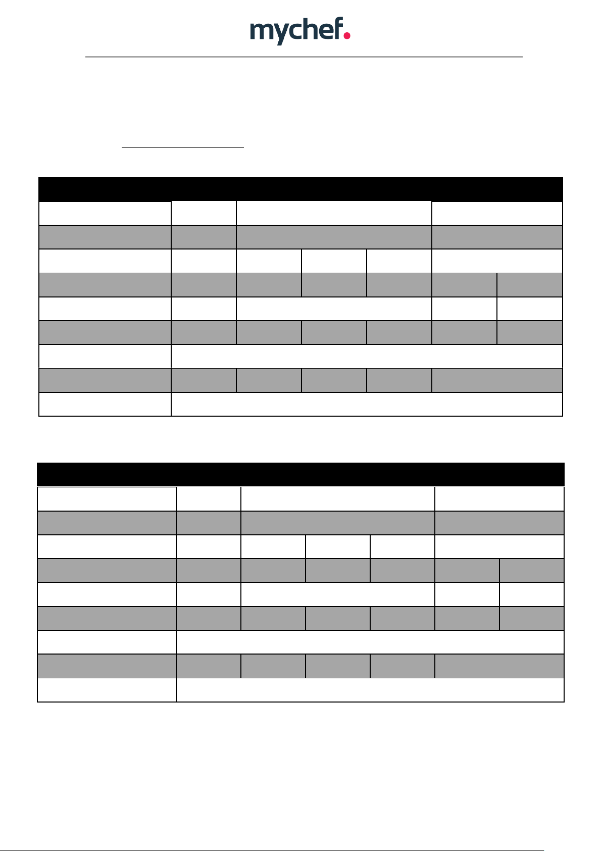
REFERENCE
TTSB06G2
TTMB10G2
TTMB16G2
TTMB20G2
TTLB21G2
TTLB22G2
External dimensions (mm)
388x491x382
475x561x454
620x571x469
Internal dimensions (mm)
328x385x162
412x453x200
560x465x210
Pump capacity (m3/h)
6
10
16
20
20
Machine cycle (S)
40
41
30
28
40
35
Sealing bar length (mm)
315
405
455
455 x2
Approximate weight (kg)
28
38
39
40
43
45
Voltage
230/1/50-60Hz
Power (kW)
0,25
0.30
0,55
0,75
0.75
Lubricant
Synthetic food grade oil SAE 10 VSL 32
REFERENCE
TTSB06E2
TTMB10E2
TTMB16E2
TTMB20E2
TTLB21E2
TTLB22E2
External dimensions (mm)
388x491x382
475x561x454
620x571x469
Internal dimensions (mm)
328x385x162
412x453x200
560x465x210
Pump capacity (m3/h)
6
10
16
20
20
Machine cycle (S)
38
40
28
26
38
33
Sealing bar length (mm)
315
405
455
455 x2
Approximate weight (kg)
28
38
39
40
43
45
Voltage
230/1/50-60Hz
Power (kW)
0.25
0.30
0,55
0,75
0.75
Lubricant
Synthetic food grade oil SAE 10 VSL 32
2.3 General tabletop model sizes
iSensor tabletop models with inert gas:
4
iSensor models for tabletop without inert gas:

2.4 General floor standing model size
REFERENCE
FSSB2*G2
FSSB4*G2
FSMB4*G2
FSMB6*G2
FSLB6*G2
FSLB1*G2
External dimensions (mm)
853x537x1032
930x607x1046
1136x707x1050
Vacuum chamber dimensions (mm)
700x430x180
800X500X200
1000x600x200
Dimensions with packaging (mm)
925x665x1300
1002x735x1314
1208x835x1318
Pump capacity (m3/h)
20
40
40
63
63
100
Machine cycle (S)
25-60 segundos
Sealing bar length (mm)
*410 + 410 mm
* 410 + 630 mm
* 410 + 410 + 580 mm
*460 + 460 mm
* 460 + 730 mm
* 460 + 460 + 680 mm
* 560 + 560 mm
* 560 + 880 mm
* 560 + 560 + 880 mm
Approximate weight (kg)
147
157
197
215
247
265
Voltage
230 V / 1L +
N/50Hz
400V / 3L + N / 50Hz
230V / 3L /50 Hz
Power (kW)
0,75
1,125
1,125
1,5
1,5
2,25
Lubricant
SAE 10 VSL 32
SAE 30 VSL100
* replace the asterisk with the desired sealing setting (2, L, U)
iSensor floor standing models with inert gas:
5
iSensor floor standing models without inert gas:

3. GENERAL SAFETY AND ACCIDENT PREVENTION REGULATIONS
3.1 Operating personnel of the machine
The use of the machine is reserved for trained personnel.
Personnel must be familiar with the safety regulations and instructions for use.
3.2 Electrical hazard
Work on the power supply and access to live parts is permitted only by qualified
personnel and at their own risk. In any case, this access must be done with the device
disconnected from the mains supply.
3.3 Thermal hazard
Keep ventilation openings clear of obstacles.
Do not install the machine in the vicinity of flammable products.
6
3.4 Hazard arising from the use of gas
The use of gas for controlled atmosphere packaging is restricted to the use of N2
nitrogen or CO2 carbon dioxide or mixtures of both.
This machine is not designed for the use of Oxygen O2 or other flammable gases.
4. INSTALLATION
Once the equipment has been received, the packaging will be carefully removed by checking
with the label (located on the back left) that it is the requested equipment. Once the
equipment has been checked, read this "Installation, use and maintenance manual" taking into
account the following precautions:
a) Personnel responsible for installation must be qualified in the installation of
machinery.
b) Check that the supply voltage/current is that required by the equipment.
c) Grounding is mandatory.
d) Check that the components of the equipment are correctly placed and undamaged
due to transport
Place the equipment on a flat surface and check that the machine is level.
The equipment must be positioned in such a way that it is protected against splashing water
and dirt.
Before starting up the equipment, check through the rear sight glass that the oil level is
between the MAX and MIN marks. If it is below the minimum, it must be filled in (see section
10 Maintenance).
7
Function
Description
A
1
Modes
Labels of the 3 operating modes: Automatic, Manual and Self Cleaning.
2
“AUTO ”Icon
Automatic mode indicator.
3
“MANUAL” Icon
Operation mode indicator Manual.
4
“CLEAN” Icon
Self-cleaning mode indicator.
5
“OFF” Icon
Indicator of the packer shutdown process.
6
Program indicator
Program display in the Manual mode. The numeric display shows the number of the selected program.
B
7
Numerical display
Shows integers from 0 to 199 or with a decimal from 0.0 to 99.9. This display shows all the numerical parameters
required during the vacuum cycle or the configuration of the packaging machine; from the vacuum level in % to
sealing times, self-cleaning, etc., passing through the error number or program selection in manual mode.
8
Error Icon
Error indicator, shows that the central numerical display shows an error value.
9
% of vacuum
Icon indicating that the central numeric display shows a value in %.
10
Seconds Icon
Icon indicating that the central numeric display shows a value in seconds.
11
Minute Icon
Icon indicating that the central numeric display shows a value in minutes.
C
12
States
Labels of the 5 operating cycle states of Vacuum, Gas, Sealing, Air and Repeat.
13
Extra vacuum
indicator
Indicator of the Extra Vacuum status, where the packer maintains 100% vacuum for a certain period of time.
14
Vacuum Icon
Vacuum status indicator. Indicates that the chamber is being vacuumed. (Pump running)
15
Gas Icon
Gas status indicator. Indicates that gas is being injected into the chamber.
16
Sealing Icon
Sealing status indicator. Indicates that the vacuum bag is being sealed.
17
Air Icon
Air status indicator. Indicates that atmospheric pressure in the chamber is recovering.
18
Cycles Icon
Repeat status indicator. Indicates the vacuum cycle repeat number and recovery in manual mode. If a multicycle
mode is set, the numeric display below the icon indicates the current cycle number in countdown.
19
Encoder push button
icon
Indicates that the cover can be closed to start operation.
20
Closed lid icon
Indicates that the cover can be closed to start operation.
21
Open lid icon
Indicates that the lid can be opened.
22
Type of air icon
Indicates the selected air inlet mode: Soft (progressive air inlet), Fast (normal air inlet) and Stop (blocking of the
vacuum percentage in the chamber for making marinades, etc.).
23
“Ready” icon
Indicates whether the machine is ready to start a new packaging cycle. If this icon flashes, the machine will be
ready after opening the filler cap.
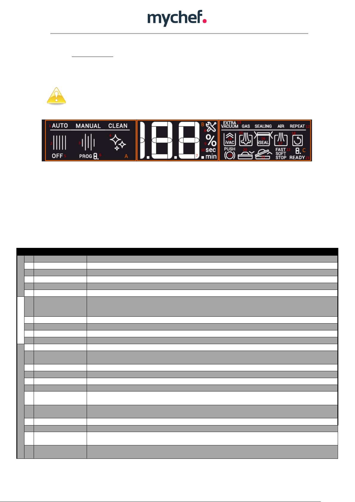
5. CONTROL PANEL
MyChef iSensor packaging machines consist of an LCD display and a rotary encoder with a
central button.
Do not clean the screen surface of the packaging machine with liquids containing
alcohol, solvents, acids or detergents that may damage the screen surface and affect
its visualization.
Figure 1. LCD Screen with the whole segments
Each zone contains a series of icons and text elements that describe at all times the state of
operation of the packaging machine and allow the user to interact with the machine, changing
the packaging parameters to suit each use. The role of each of them is explained below:
The LCD display is structured in three main zones:
- The left zone or operating mode zone(A in Figure 1)
- The central zone or zone of vacuum percentage level and error indicator (B in Figure 1)
- The right zone or status zone (C in Figure 1)
Table 1. Control board indicators, displays and buttons

8
6. CALIBRATION
6.1 Self Calibration system SCS
The iSensor tabletop and floor-standing packers have a fully automatic calibration system, Self
Calibration System (SCS), patented by myChef. As a result of this automatic recalibration
algorithm of the vacuum percentage, we have the following advantages:
Calibration without user intervention
The vacuum packer automatically detects optimal calibration conditions and can be
calibrated autonomously based on the following physical changes:
Automatic adaptation to temperature variations
Automatic adaptation to climatic variations
Automatic adaptation to height variations
Automatic adaptation to changes in oil properties.
The machine is capable of detecting both increases and decreases in the differential
pressure of the atmosphere, recalibrating accordingly.
Greater accuracy in vacuum measurement
When calibrated constantly and automatically, the values used to calculate the vacuum
percentage are dynamically updated. Therefore, the percentage of vacuum selected by the
user has a lower error than if calibration was not performed dynamically.

9
7. OPERATION
7.1 Powering and switching on the machine
When the machine is turned on, a start-up process takes place where all internal values are
initialized and safety and control checks are carried out to ensure optimum control of the
packaging. This will be displayed on the screen with all segments flashing simultaneously for a
few seconds.
During this blinking, technical control parameters can be called up by pressing the encoder
button. These parameters may be relevant for maintenance purposes. Specifically, it will show
two parameters:
- Vacuum pump operating hours.
- Number of vacuum cycles performed.
The first value displayed is the operating hours of the vacuum pump. This will be identified by
the "Vacuum" icon, which will light up in the right-hand block of the screen. The digits of the
number will be shown on the central display cyclically by marking the end of the digits with an
"H". For example, if the pump motor has been running for 20991 hours, the display will
show:"2 - 0 - 9 - 9 - 9 - 1 - H", looped.
Figure 2. Display of vacuum pump operating hours
By pressing the push-button while the number of pump operating hours is displayed, the filler
will go on to show the number of complete vacuum cycles it has completed. The value will be
displayed using the same method, changing the "H" that identifies the end of the number of
operating hours to a "C" for packaging cycles. In this case the value will be identified by the
"Repeat" icon.
Figure 3. Displaying the number of vacuum cycles performed
Press the central button again to finish displaying this value and continue the machine start
process.
Once the packaging machine is connected and the initialization process is completed (whether
or not the status values of the pump are consulted), it will be switched off, waiting for the user
to switch it on to start working.
The machine can be switched on in three different ways:
- Using the encoder push button.
- Rotating the encoder in any direction.

10
- Opening the lid.
Any interaction will start it in automatic mode so that with only one more movement of the lid
it can start to pack.
¡WARNING! The Manufacturer shall not be liable for any injury to persons or animals
and damage to components resulting from improper use and not in conformity with
the machine.
7.2 Inert gas injection
In some foods, it may be interesting or advisable to use antioxidant gas to improve the
preservation of the same or also mixtures of gas to avoid crushing the packaged product. This
option is available with all myChef iSensor vacuum packers’ machines
The following is a description of the precautions to be taken into account when carrying out
vacuum packaging in a protective atmosphere:
NEVER USE FLAMMABLE GASES OR MIXTURES IN WHICH THERE IS TOO MUCH
OXYGEN, THE OXYGEN CAUSES THE FLAMMABILITY POINT OF THE MATERIALS TO
DROP AND THERE IS A RISK OF EXPLOSION.
THE INSTALLATION MUST BE DONE BY A SPECIALIZED TECHNICIAN.
GAS TANKS MUST BE SECURELY FASTENED.
THE GAS OUTPUT PRESSURE OF THE PUMP SHOULD NOT EXCEED 1 bar BECAUSE A
HIGHER PRESSURE MAY DAMAGE THE COMPENENTS OF THE PACKAGING MACHINE
ONCE THE LAST GAS OPERATION HAS BEEN MADE, CLOSE THE STOPCOCK OF THE GAS
TANKS.
TO CONNECT THE GAS INPUT TO THE PACKAGING MACHINE A FLEXIBLE 10mm
ØINTERIOR TUBE THAT SUPPORTS PRESSURE AND SECURES THE CONNECTOR WITH A
METALLIC FLANGE WILL BE NEEDED TO BE CONNECTED.
7.3 Operating modes
ISensor packers have three different operating modes: Automatic mode, Manual mode and
Self-Cleaning mode. The operating mode is selected by rotating the encoder until the
corresponding icon is highlighted in the left menu of the LCD screen.
7.3.1 Automatic mode
The automatic mode of operation is designed so that the user can pack perfectly and
efficiently without having to configure any parameters. This mode performs a complete
packaging cycle without the need for monitoring: it produces vacuum in the pouch by
controlling the vacuum percentage with the intelligent iVAC algorithm, seals it hermetically by
regulating the seal duration with the iSeal algorithm and automatically recovers atmospheric
pressure in the chamber.

11
Figure 4. Automatic mode.
MyChef patented iVAC control algorithm automatically detects and completes the vacuum
process depending on the type of food and its conditions. It is particularly suitable for the
packaging of porous foods and liquids as it prevents them from boiling and overflowing out of
the bag.
On the other hand, the iSeal algorithm regulates the sealing time of each cycle to avoid
overheating in the bar and thus avoid burning the bag. This allows the bar temperature to be
adjusted to each seal, extending the service life of all bar components and guaranteeing
perfect seals regardless of the number of cycles previously performed.
To start it, just select the automatic mode by rotating the encoder and lower the cover once
the "AUTO" icon is on.
7.3.2 Manual mode:
The manual mode allows the user to fully control the packaging parameters and access special
features such as repeat vacuum cycles or extra sealing times.
Figure 5. Manual mode.
Once the "MANUAL" icon has been selected, the "PROG" icon at the bottom left of the screen
will light up and the digit next to it will indicate the selected program. By default this will be 0.
By pressing the button, the program icon will blink, allowing you to select the different
programs when rotating the encoder.
This mode is organized in 10 packaging programs, from 0 to 9. These allow you to configure
packaging parameters for a specific purpose such as making marinades or vacuuming products
with bones or pieces that may damage the bag. The programs allow you to save these
parameters and load them quickly every time you want to pack with the same characteristics.
These values do not have to be edited and entered each time, making it easy to perform
specific packaging processes multiple times over.
To edit the parameter values, press the encoder button with the selected program to be
modified. On the right size of the LCD screen, the icon related to the parameter to be modified
will start flashing; for example, if the vacuum level to be reached is changed, the "VACUUM"
icon will start flashing (later all the parameters and their relationship with the LCD screen icons
are presented). Then by rotating the encoder, you can modify the parameter value and
pressing it again saves it and jumps to the next value to be set. This process will be repeated
until all parameters are modified and saved, returning to the manual mode starting point.
If you want to use a previously configured and saved program without editing any options, you
can close the cover once you have selected the program in question. The packaging machine
enters the manual vacuum cycle according to the parameters stored in the memory without
any modification or confirmation of each value.

Figure 6. Parameters that the user can modify
All parameters are described below in configuration order:
- Vacuum percentage:
This parameter sets a vacuum value per cent, once this value is reached the pump will
switch off and jump to the next state. Once the value "Int" has been selected, the
vacuum percentage control is delegated to the iVAC algorithm explained in the
automatic mode. The icon that identifies it is the "VACUUM" icon.
- Vacuum extra time:
The extra vacuum time marks a time in seconds during which the vacuum pump is kept
turned on. This bonus is used to guarantee vacuum in very porous foods. For proper
operation this time can only be set when 100% vacuum is selected. The icon that
identifies it is the "EXTRA" icon.
12
- Gas percentage:
This parameter determines the value of the percentage of gas with which the chamber
will be filled. This value is conditioned by the percentage of vacuum selected in the
previous parameter; The vacuum level minus the gas level must be at least 50%. The
icon that identifies it is the "GAS" icon.
- Sealing time:
This time value specifies the seal time of the bag. It marks the duration of electrical
contact on the sealing bars and must be adjusted to each type of bag. In order to know
the ideal time it is recommended to consult with the bag supplier. As in the selection
of the vacuum percentage, selecting the "Int" value delegates’ control of the sealing
time to the iSeal algorithm that will regulate this time automatically. The icon that
identifies it is the "SEALING" icon.
- Atmospheric pressure recovery mode:
This parameter allows the selection of 3 types of air inlet:
1. FAST: The atmospheric pressure recovery in FAST mode allows the air to be blown in
by opening the inlet valve until the atmospheric pressure inside the chamber recovers.
It is the quickest and most suitable way in most cases.
2. SOFT: The pressure recovery in SOFT mode allows the air to enter intermittently,
controlling the deformation of the bag. This mode is useful for slowly restoring
atmospheric pressure so that the packaged food is properly molded to the pouch and
preventing sharp objects from breaking it.
3. STOP: This mode allows the pump to stop at a certain vacuum value by pressing the
encoder button or until it reaches the value determined by the vacuum percentage
parameter. The vacuum packer will hold this vacuum until the button is pressed again.
This process can be useful for marinating meat or fish or for extracting air from sauces.

13
The icon that identifies it is the "AIR" icon and selecting each type of recovery is done using the
icons below it: "FAST","SOFT" and "STOP".
- Repeat multiple vacuum cycles:
It is possible to program series of repetitions of the same vacuum cycle, i. e. it allows
the vacuum to be carried out and the atmospheric pressure in the packaging machine
to be restored cyclically. In each repetition, the packer reaches the vacuum value set in
the "Vacuum percentage" parameter. If this is 100% and an extra vacuum time is set,
this time is also completed within each repetition. The atmospheric pressure inside the
chamber is then recovered. This recovery is not fully completed as a small percentage
of vacuum is kept in the chamber to avoid opening the lid, allowing another repetition
to start automatically.
This process will perform as many repetitions as defined in this value, with a maximum
of 9. The icon that identifies it is the "REPEAT" icon and the digit below it marks the
number of repetitions remaining.
The gas injection is compatible with the cycle repeat mode, although it should be
noted that the gas will be injected only at the last repetition, in the same way that it is
injected when sealing is performed.
7.3.3 Autoclean:
When the oil in the vacuum pump has become whitish due to water condensation, this can be
removed with this mode. This process helps the water in the oil to evaporate due to
temperature.
These water particles can cause rust particles to appear in internal pump components.
Every 200 vacuum cycles, the vacuum packer will alert the user to perform a self-cleaning
process. This will happen when the machine is connected or switched on. If the lid is
closed during this period the "AUTO-CLEAN OIL" process will start automatically.
If you don't want to do the AUTOCLEAN at the time of the warning, you can rotate the
encoder to navigate through the menu and perform the cycle of your choice.
An AUTOCLEAN cycle can be performed whenever desired by entering the AUTOCLEAN mode
manually in the operating mode selection menu. The maximum duration of the AUTO-CLEAN
mode is 20 minutes, although it can be stopped by pressing the encoder button.
7.4 Packaging
In order to pack a product, the bag (suitable for vacuum packaging) must be placed correctly
on top of the polyethylene plate, the entire bag width must be above the sealing area. Make
sure that there is no product on the sealing bar. Then lower the lid of the packaging machine.
It is important to remember that a packaging process cannot be started while the manual
mode parameters are being set.
NOTE: It is recommended to use the safety latch on each packaging cycle, at this point the
active mode or program is started and the indicators of the processes to be carried out

14
(vacuum, extra vacuum, gas injection, sealing, progressive air inlet, repetitions) are illuminated
continuously:
- The vacuum process (VACUUM) extracts the air from the chamber and the central
display shows the percentage of vacuum achieved so far.
- The vacuum plus process (EXTRA VACUUM) keeps the vacuum pump running during
the programmed seconds. This is used to extract air from very porous food. The
central display shows the elapsed seconds.
- The gas injection (GAS) fills the chamber with the percentage of gas specified in the
program. The percentage of gas entered is also shown on the central display.
- The seal consists of three phases. The first is the lifting of the cylinders. During this
phase, the fixed value of the sealing duration in seconds is shown in the central
display. The second is resistance heating. In this phase the SEAL display will
progressively decrease from the previous value. The third phase, which lasts five
seconds, is the cooling of the bag and in it the SEAL display increases progressively up
to 5.0 seconds.
- The last phase is the recovery of atmospheric pressure (AIR). The display will show the
percentage of vacuum in the chamber decreasing. During this phase, the selected type
of atmospheric recovery will also illuminate; SOFT or FAST.
The active process is signalled by the associated indicator light. Once the process is complete,
the indicator will turn off.
If repetitions of packaging cycles (REPEAT) have been set up, they will be done at the start of
packaging. The "REPEAT" icon will light up and the "VACUUM","EXTRA VACUUM" or "AIR" icon
will also light up, depending on whether vacuum in the chamber, extra vacuum time or
atmospheric pressure is being recovered. Each time a repetition is made, the digit below the
"REPEAT" icon will decrease its value until it is passed to the last packaging cycle.
All processes except pressure recovery in the vacuum chamber can be cancelled by pressing
the encoder button while running. This will take you to the next step in the cycle until you
reach the air inlet where it will end.
If the vacuum is not correctly performed, the machine will display an error (see 8).
3-minute rest periods are recommended between cycle.

15
Error
Descripción
Solución
E01
Lowered lid
Open the lid. If the error persists, call your service technician indicating the
error code.
E02
Vacuum system failure
The system has detected that the vacuum pump has been running too long to
reach a certain vacuum level. Perform a system calibration. If the calibration is
successful, perform the test again. If not, call for service. The maximum running
time is 2 minutes.
E03
Fault in the vacuum sensor
(minimum)
Check the connection tube to the vacuum sensor for leaks or poor connection.
If you think everything is OK, call the service department indicating the error
code and the value of the central display just before the error.
E04
Fault in the vacuum sensor
(maximum)
Check the connection tube to the vacuum sensor for leaks or poor connection.
If you think everything is OK, call the service department indicating the error
code and the value of the central display just before the error.
E05
Internal Error
The control board has detected an internal error. Call your service
representative indicating the error code.
8. ERRORS
The machine has algorithms that allow the detection of anomalous situations that can lead to
a malfunction of the machine. These situations are reported to the user via an error screen as
shown below:
Figure 7. Errors display
The table below shows the errors and possible solutions:
Table 2. Errors and possible solutions
Due to automatic checks the machine can be turned off to avoid serious failure. Switch it on
normally.
In case of an error in the packaging machine, please contact the technical service.

9. MAINTENANCE
After any handling for cleaning, maintenance or repair, the equipment must be
disconnected from the mains supply.
If the power cord is damaged, it must be replaced by the manufacturer, its service
department or similarly qualified personnel in order to avoid danger.
9.1 Cleaning
Clean the vacuum packer regularly and carefully.
Cleaning the packer with high pressure cleaning equipment is HARMFUL to the
equipment and could result in breakage of the equipment and could result in loss of
the bottler's WARRANTY.
For the stainless steel housing, use a cloth dampened with water and detergent.
The lid must be cleaned with a cloth dampened with water and neutral detergent. DO
NOT USE ANY LIQUIDS CONTAINING ALCOHOL, ACID, DETERGENTS, SOLVENTS OR
EQUIVALENT FOR CLEANING THE LID.
16
Failure to comply with these instructions may cause the lid to break and will result in loss of
warranty on the lid.
9.2 Oil vacuum pump
Carry out periodic oil level checks, possibly complete if necessary, respecting the maximum
and minimum levels.
Use the type of oil recommended by the manufacturer of the vacuum pump (depending on the
model).
An oil in good condition must have a transparent colour. If it becomes white, this means that it
has acquired water due to condensation of the sucked in humid air, which would mean that it
has lost its characteristics and needs to be replaced.
The oil may also acquire a darker shade because it has sucked in dirt, which would mean that it
has lost its properties and needs to be replaced.
The vacuum pump used by this equipment is not designed to operate in extremely cold or
extremely hot environments. Operating temperature range 12/35°C.
9.3 Welding bar
Periodically check the condition of Teflon adhesive tape and sealing tape. These must be in
perfect condition and without knocks.
9.4 Lid gasket
Periodically check the condition of the sealing gasket on the cover. This one has to be in
perfect condition.

10. MAINTENANCE SCHEDULE
First 100 hours of operation
Change oil in the vacuum pump
Weekly or when the CLN message appears
on the packaging machine
Performing an auto-cleaning program
Check oil level
Check sealing bar condition
Check seal gasket lid condition
Semi-annually or every 500 hours of
operation
Change oil in the vacuum pump
Every 1000 operating hours
Change oil filter
Annually
Check for leaks in the vacuum circuit
It is recommended that maintenance work be carried out by a qualified person
or by your dealer or service technician.
10.1 Check the oil level
17
Table 3. Maintenance schedule
The rear cover does not need to be removed to check the oil level of the pump.
Illustration 1. Oil level indicator

10.2 Changing the pump oil
Caution: Before disassembling any components, make sure that the equipment is
disconnected from the mains supply and the inert gas connection.
Material required for oil change:
Material: Synthetic food grade oil SAE 10 VSL32 (table-top models ") Synthetic oil
SAE 30 VSL 100 (Floor standing models).
18
Illustration 2. Oil replacement kit
Tools:
o Allen screwdriver 3.
o Universal wrench.
10.2.1 Table top models
Step 1Unscrew the two rear screws
Unscrew, with the aid of the Allen key 3, the two screws on the back of the sides (Do not
disassemble the two front screws, the bowl pivots on them). Once these two have been
removed, loosen the central screw on the back with the same screwdriver (it is not necessary
to remove it completely).

Illustration 4. Hinged opening system
Illustration 3. Rear screws
Rear lateral part
Rear part
(Only loosen)
19
Step 2 Opening of the hinged system
Like the hood of a car, lift the rear of the packer until it stops.

Step 3 Open the cap to drain the pump
Illustration 5. Remove the oil drain plug
Using a universal wrench remove the oil drain plug from the pump.
20
Place a container under the hole so that the oil drains into it and does not contaminate the
floor of the packer.
Illustration 6. Oil drain
When all the oil has come out, put the cap back on.
Step 4 Open the oil filler cap.
With the help of the universal wrench we open the oil filler cap and, helping us, from a funnel
we pour the oil to the maximum of the packaging machine.

21
Illustration 7. Remove the oil filler cap and refill with new oil.
The oil level must be between the MIN and MAX limits indicated by the sight glass on the
pump.
Step 5 We close the filler oil cap
With the help of the universal wrench we close the oil filler cap and proceed to reverse process
to leave the machine operational.

10.2.2 Floor standing models
Illustration 8. Remove the 6 screws at the back
Illustration 9. Position of the drain plug
Position of the 6 screws
Drain stopper
Step 1: Unscrew the 6 screws at the rear with the Allen key 3.
22
Step 2 Remove the back cover and locate the pump.
Step 3 Open the cap to drain the pump
For the standing models, all pump plugs are located on the rear side as shown in Illustration 9.
Once the emptying plug has been located, proceed as in step 3 of section 10.2.1.
Step 4 Open the oil filler cap.
For models with 20 m3/h and 40 m3/h pumps, the fill plug is located at the top of the pump,
while for 63 m3/h and 100 m3/h models, the plug is on the right side just above the oil sight
glass.
Now with the help of a funnel we fill the pump until the oil level is between the MAX and MIN
marks that appear as a reference in the oil sight glass.

23
Step 5 Close the oil filler cap
With the help of the universal wrench we close the oil filler cap and proceed to reverse process
to leave the machine operational.
Step 6 We close the back of the packaging machine
With the help of the Allen wrench we replace the rear cover and the oil change will be
complete.
10.3 Other maintenance operations
Other maintenance operations, such as changing the oil filter, must be carried out by qualified
technicians or by your dealer or service personnel.
10.4 Owner’s liability
IT IS THE RESPONSIBILITY OF THE OWNER TO PERFORM REGULAR MAINTENANCE. IT MUST
BE POSSIBLE TO CHECK THAT THE MAINTENANCE HAS BEEN CARRIED OUT.
If the vacuum packing machine is subjected to harsh conditions, such as low temperatures
(below 12-15°C) or frequent short operating periods, checks must be carried out more
frequently.

11. SPECIFICATIONS
DISTFORM, SL. (SPAIN) CIF: B-25262726
Año: 2010
Modelo: TTMB20G2
Nº serie: 111111/001
Tensión: 230 Vac Frecuencia: 50HZ
Potencia: 750 W Gas: --
GIP: 65 Carga gas: --
The packaging machine has a type plate with the following specifications and references:
Manufacturer: Distform, S.L.
Carrer Tramontana, s/n
25123 Torrefarrera (Lleida)
Model
Serial number
Electrical characteristics
Year of manufacture
24
This packaging machine has been manufactured according to the following standards:
- UNE-EN 60335-1
- UNE-EN 60335-2-64
- EN 12100-1
- EN 12100-2
-
And it complies with the low voltage (2006/95/CE), electromagnetic compatibility
(2004/108/EC) and machinery (2006/42/EC) directives.
It is forbidden to damage, remove, modify, cover or alter the type/identification plate
of the equipment and must always remain visible. The alteration or removal of the
same may result in loss of warranty.

11.1 General wiring diagram iSensor tabletop SMALL, MEDIUM Y LARGE
25

26
11.1.2 General Standard wiring diagram iSensor floor standing SMALL, MEDIUM Y LARGE

2
1
2
1
2
1
VACUUM PACKAGE
M
GAS IN
Gas models only
ATMOSPHERE IN
CYLINDERS
11.2 Pneumatic diagram
27
 Loading...