

Mychef FSSB22G2, iSENSOR, TTSB06G2, FSSB2UG2, FSSB2LG2 Installation, Operation And Maintenance Manual
...
INSTALLATION, OPERATION AND MAINTENANCE MANUAL
iSENSOR

1
Index
1. INTRODUCTION ..................................................................................................................... 3
2. TECHNICAL CHARACTERISTICS .............................................................................................. 3
2.1 Functional equipment ................................................................................................... 3
2.2 Constructive features .................................................................................................... 3
2.3 General tabletop model sizes ........................................................................................ 4
2.4 General floor standing model sizes ............................................................................... 5
3. GENERAL SAFETY AND ACCIDENT PREVENTION REGULATIONS ........................................... 6
3.1 Operating personnel of the machine ............................................................................ 6
Personnel must be familiar with the safety regulations and instructions for use. ................... 6
3.2 Electrical hazard ............................................................................................................ 6
3.3 Thermal hazard ............................................................................................................. 6
3.4 Hazard arising from the use of gas ................................................................................ 6
This machine is not designed for the use of Oxygen O2 or other flammable gases. .................... 6
4. INSTALLATION ....................................................................................................................... 6
5. CONTROL PANEL.................................................................................................................... 7
6. CALIBRATION ......................................................................................................................... 8
6.1 Self Calibration system SCS ........................................................................................... 8
7. OPERATION ........................................................................................................................... 9
7.1 Powering and switching on the machine ...................................................................... 9
7.2 Inert gas injection ........................................................................................................ 10
7.3 Operating modes ......................................................................................................... 10
7.3.1 Automatic mode .................................................................................................. 10
7.3.2 Manual mode ...................................................................................................... 11
7.3.3 Autoclean ............................................................................................................ 13
7.4 Packaging ..................................................................................................................... 13
8. ERRORS ................................................................................................................................ 15
9. MAINTENANCE .................................................................................................................... 16
9.1 Cleaning ....................................................................................................................... 16
9.2 Vaccum pumb oil ......................................................................................................... 16
9.3 Welding bar ................................................................................................................. 16
9.4 Lid gasket ..................................................................................................................... 16
10. MAINTENANCE SCHEDULE .............................................................................................. 17
10.1 Check the oil level ....................................................................................................... 17
10.2 Changing the pump oil ................................................................................................ 18

2
10.2.1 Table top models ................................................................................................. 18
10.2.2 Fool standing models .......................................................................................... 22
10.3 Other maintenance operations ................................................................................... 23
10.4 Owner’s liability ........................................................................................................... 23
11. SPECIFICATIONS............................................................................................................... 24
11.1 General wiring diagram iSensor Tabletop SMALL, MEDIUM Y LARGE ........................ 25
11.1.2 General wiring diagram iSensor Floor standing SMALL, MEDIUM Y LARGE ........... 26
11.2 Pneumatic diagram ..................................................................................................... 27

1. INTRODUCTION
Removable solder bar without
connections.
Possibility of programming up to 9 work
cycles.
Optional inert gas inlet on all models.
External vacuum accessory for all iSensor
tabletop models (optional).
Progressive pressure recovery to avoid
damage to the bag caused by spines,
bones, etc....
Polyethylene plate inside the chamber,
which increases the vacuum speed and
regulates the working height.
Controlled visualization of all process
steps.
Vacuum control by sensor.
Auto-calibration system
Vacuum plus vacuum to force air out of
porous products.
Intelligent mode for packaging liquids
and porous products (iVac).
AUTO-CLEAN OIL process, self-cleaning
oil system.
Standard external vacuum for all tabletop
models.
Double sealing 2x3 mm for iSensor
tabletop packaging machines.
Double welding 2x4 mm for iSensor floor
standing packers.
Built in stainless steel.
The tank has rounded edges for easy
cleaning.
Transparent methacrylate lid to visualize
the element to be packed.
For standing models, 4 wheels two with
brake for easy mobility.
Rear oil level indicator
For floor standing models, it is possible to
choose the sealing shape:
This document has been prepared and to provide reliable and helpful information for the use
of the equipment. The manufacturer disclaims any implied or explicit liability for any errors or
omissions it may contain.
Before carrying out any intervention or use of the machine, it is recommended to read
this manual carefully and completely.
The owner of the equipment is obliged to have this manual read by the personnel in
charge of its operation and maintenance.
2. TECHNICAL CHARACTERISTICS
2.1 Functional equipment
3
NOTE: The floor standing models are factory wired to 400V with 3 phases plus a neutral, if you
want the 230V voltage with 3 phases will be provided a technical note for a specialized SAT to
make the change.
2.2 Constructive features
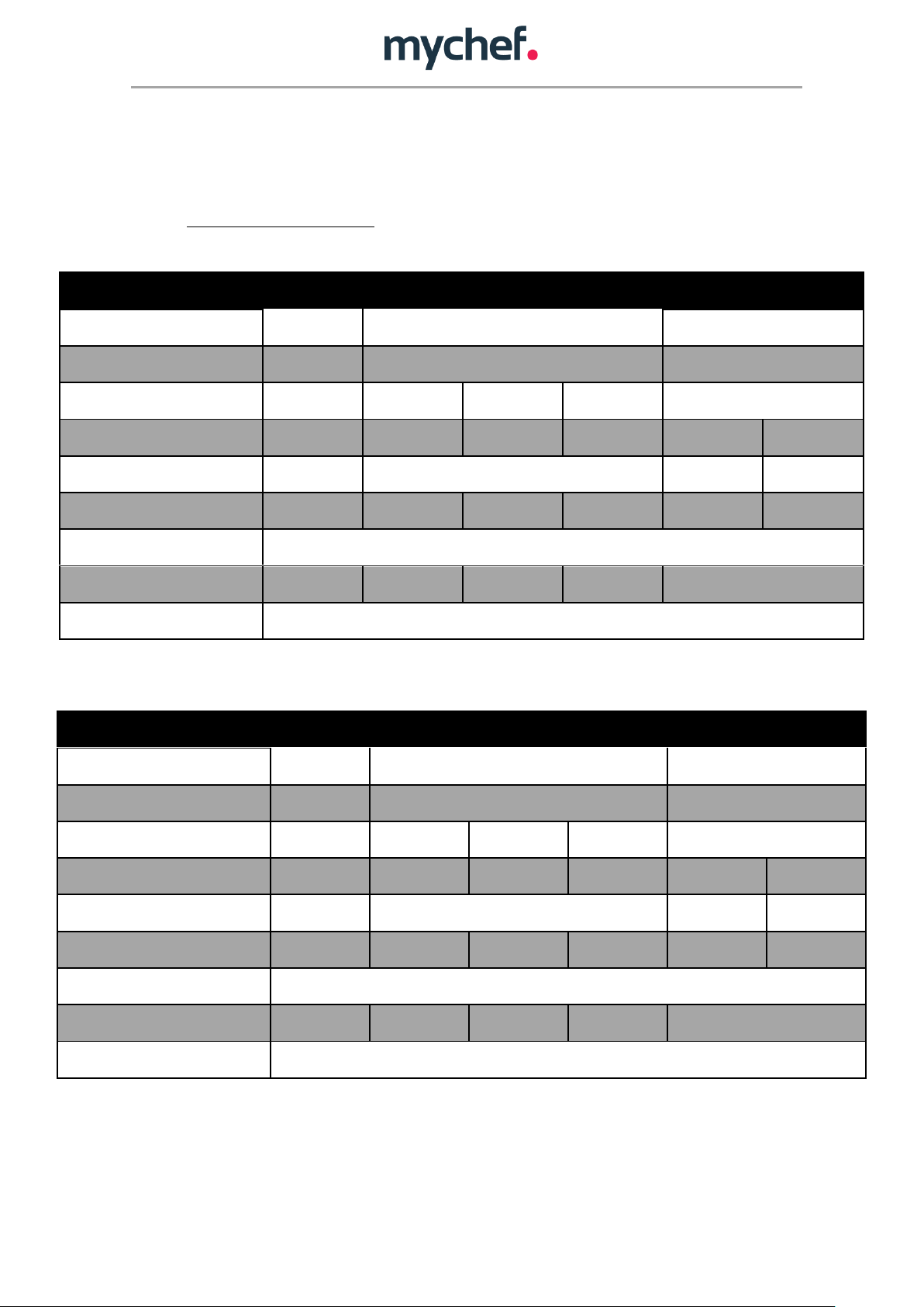
REFERENCE
TTSB06G2
TTMB10G2
TTMB16G2
TTMB20G2
TTLB21G2
TTLB22G2
External dimensions (mm)
388x491x382
475x561x454
620x571x469
Internal dimensions (mm)
328x385x162
412x453x200
560x465x210
Pump capacity (m3/h)
6
10
16
20
20
Machine cycle (S)
40
41
30
28
40
35
Sealing bar length (mm)
315
405
455
455 x2
Approximate weight (kg)
28
38
39
40
43
45
Voltage
230/1/50-60Hz
Power (kW)
0,25
0.30
0,55
0,75
0.75
Lubricant
Synthetic food grade oil SAE 10 VSL 32
REFERENCE
TTSB06E2
TTMB10E2
TTMB16E2
TTMB20E2
TTLB21E2
TTLB22E2
External dimensions (mm)
388x491x382
475x561x454
620x571x469
Internal dimensions (mm)
328x385x162
412x453x200
560x465x210
Pump capacity (m3/h)
6
10
16
20
20
Machine cycle (S)
38
40
28
26
38
33
Sealing bar length (mm)
315
405
455
455 x2
Approximate weight (kg)
28
38
39
40
43
45
Voltage
230/1/50-60Hz
Power (kW)
0.25
0.30
0,55
0,75
0.75
Lubricant
Synthetic food grade oil SAE 10 VSL 32
2.3 General tabletop model sizes
iSensor tabletop models with inert gas:
4
iSensor models for tabletop without inert gas:

2.4 General floor standing model size
REFERENCE
FSSB2*G2
FSSB4*G2
FSMB4*G2
FSMB6*G2
FSLB6*G2
FSLB1*G2
External dimensions (mm)
853x537x1032
930x607x1046
1136x707x1050
Vacuum chamber dimensions (mm)
700x430x180
800X500X200
1000x600x200
Dimensions with packaging (mm)
925x665x1300
1002x735x1314
1208x835x1318
Pump capacity (m3/h)
20
40
40
63
63
100
Machine cycle (S)
25-60 segundos
Sealing bar length (mm)
*410 + 410 mm
* 410 + 630 mm
* 410 + 410 + 580 mm
*460 + 460 mm
* 460 + 730 mm
* 460 + 460 + 680 mm
* 560 + 560 mm
* 560 + 880 mm
* 560 + 560 + 880 mm
Approximate weight (kg)
147
157
197
215
247
265
Voltage
230 V / 1L +
N/50Hz
400V / 3L + N / 50Hz
230V / 3L /50 Hz
Power (kW)
0,75
1,125
1,125
1,5
1,5
2,25
Lubricant
SAE 10 VSL 32
SAE 30 VSL100
* replace the asterisk with the desired sealing setting (2, L, U)
iSensor floor standing models with inert gas:
5
iSensor floor standing models without inert gas:

3. GENERAL SAFETY AND ACCIDENT PREVENTION REGULATIONS
3.1 Operating personnel of the machine
The use of the machine is reserved for trained personnel.
Personnel must be familiar with the safety regulations and instructions for use.
3.2 Electrical hazard
Work on the power supply and access to live parts is permitted only by qualified
personnel and at their own risk. In any case, this access must be done with the device
disconnected from the mains supply.
3.3 Thermal hazard
Keep ventilation openings clear of obstacles.
Do not install the machine in the vicinity of flammable products.
6
3.4 Hazard arising from the use of gas
The use of gas for controlled atmosphere packaging is restricted to the use of N2
nitrogen or CO2 carbon dioxide or mixtures of both.
This machine is not designed for the use of Oxygen O2 or other flammable gases.
4. INSTALLATION
Once the equipment has been received, the packaging will be carefully removed by checking
with the label (located on the back left) that it is the requested equipment. Once the
equipment has been checked, read this "Installation, use and maintenance manual" taking into
account the following precautions:
a) Personnel responsible for installation must be qualified in the installation of
machinery.
b) Check that the supply voltage/current is that required by the equipment.
c) Grounding is mandatory.
d) Check that the components of the equipment are correctly placed and undamaged
due to transport
Place the equipment on a flat surface and check that the machine is level.
The equipment must be positioned in such a way that it is protected against splashing water
and dirt.
Before starting up the equipment, check through the rear sight glass that the oil level is
between the MAX and MIN marks. If it is below the minimum, it must be filled in (see section
10 Maintenance).
7
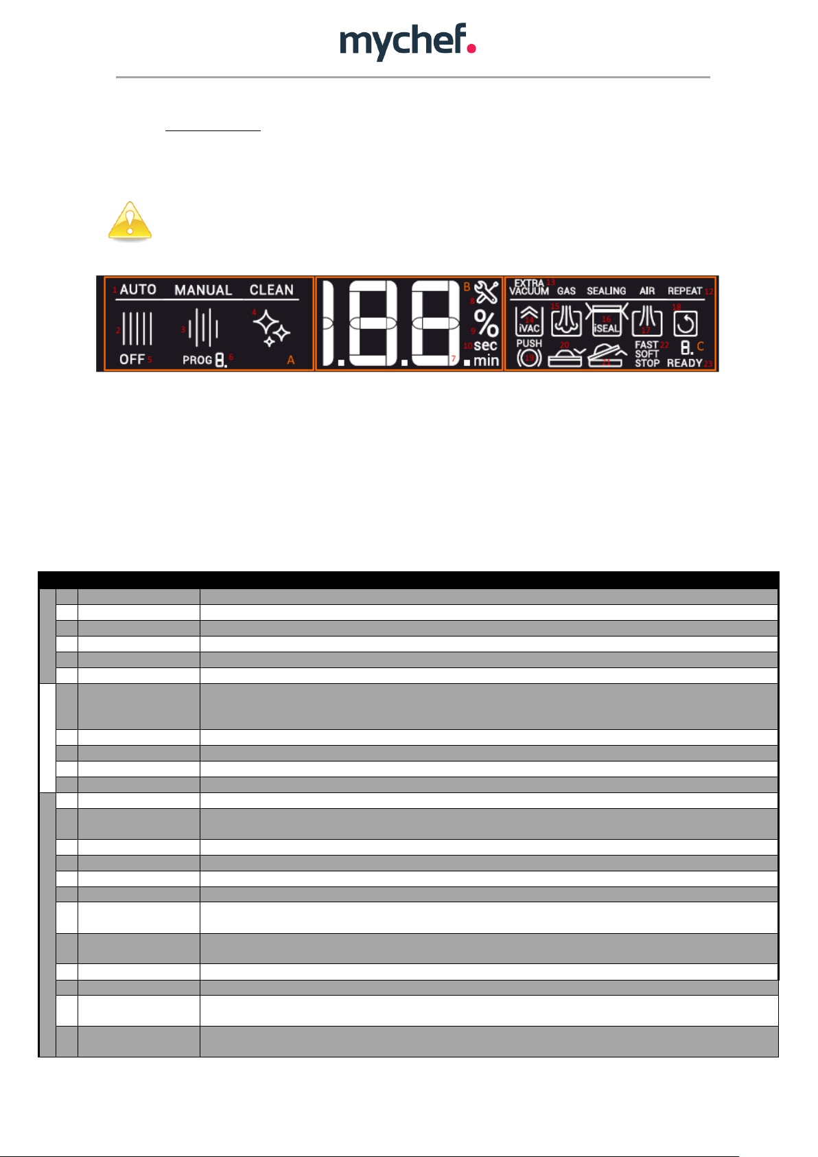
Function
Description
A
1
Modes
Labels of the 3 operating modes: Automatic, Manual and Self Cleaning.
2
“AUTO ”Icon
Automatic mode indicator.
3
“MANUAL” Icon
Operation mode indicator Manual.
4
“CLEAN” Icon
Self-cleaning mode indicator.
5
“OFF” Icon
Indicator of the packer shutdown process.
6
Program indicator
Program display in the Manual mode. The numeric display shows the number of the selected program.
B
7
Numerical display
Shows integers from 0 to 199 or with a decimal from 0.0 to 99.9. This display shows all the numerical parameters
required during the vacuum cycle or the configuration of the packaging machine; from the vacuum level in % to
sealing times, self-cleaning, etc., passing through the error number or program selection in manual mode.
8
Error Icon
Error indicator, shows that the central numerical display shows an error value.
9
% of vacuum
Icon indicating that the central numeric display shows a value in %.
10
Seconds Icon
Icon indicating that the central numeric display shows a value in seconds.
11
Minute Icon
Icon indicating that the central numeric display shows a value in minutes.
C
12
States
Labels of the 5 operating cycle states of Vacuum, Gas, Sealing, Air and Repeat.
13
Extra vacuum
indicator
Indicator of the Extra Vacuum status, where the packer maintains 100% vacuum for a certain period of time.
14
Vacuum Icon
Vacuum status indicator. Indicates that the chamber is being vacuumed. (Pump running)
15
Gas Icon
Gas status indicator. Indicates that gas is being injected into the chamber.
16
Sealing Icon
Sealing status indicator. Indicates that the vacuum bag is being sealed.
17
Air Icon
Air status indicator. Indicates that atmospheric pressure in the chamber is recovering.
18
Cycles Icon
Repeat status indicator. Indicates the vacuum cycle repeat number and recovery in manual mode. If a multicycle
mode is set, the numeric display below the icon indicates the current cycle number in countdown.
19
Encoder push button
icon
Indicates that the cover can be closed to start operation.
20
Closed lid icon
Indicates that the cover can be closed to start operation.
21
Open lid icon
Indicates that the lid can be opened.
22
Type of air icon
Indicates the selected air inlet mode: Soft (progressive air inlet), Fast (normal air inlet) and Stop (blocking of the
vacuum percentage in the chamber for making marinades, etc.).
23
“Ready” icon
Indicates whether the machine is ready to start a new packaging cycle. If this icon flashes, the machine will be
ready after opening the filler cap.
5. CONTROL PANEL
MyChef iSensor packaging machines consist of an LCD display and a rotary encoder with a
central button.
Do not clean the screen surface of the packaging machine with liquids containing
alcohol, solvents, acids or detergents that may damage the screen surface and affect
its visualization.
Figure 1. LCD Screen with the whole segments
Each zone contains a series of icons and text elements that describe at all times the state of
operation of the packaging machine and allow the user to interact with the machine, changing
the packaging parameters to suit each use. The role of each of them is explained below:
The LCD display is structured in three main zones:
- The left zone or operating mode zone(A in Figure 1)
- The central zone or zone of vacuum percentage level and error indicator (B in Figure 1)
- The right zone or status zone (C in Figure 1)
Table 1. Control board indicators, displays and buttons

8
6. CALIBRATION
6.1 Self Calibration system SCS
The iSensor tabletop and floor-standing packers have a fully automatic calibration system, Self
Calibration System (SCS), patented by myChef. As a result of this automatic recalibration
algorithm of the vacuum percentage, we have the following advantages:
Calibration without user intervention
The vacuum packer automatically detects optimal calibration conditions and can be
calibrated autonomously based on the following physical changes:
Automatic adaptation to temperature variations
Automatic adaptation to climatic variations
Automatic adaptation to height variations
Automatic adaptation to changes in oil properties.
The machine is capable of detecting both increases and decreases in the differential
pressure of the atmosphere, recalibrating accordingly.
Greater accuracy in vacuum measurement
When calibrated constantly and automatically, the values used to calculate the vacuum
percentage are dynamically updated. Therefore, the percentage of vacuum selected by the
user has a lower error than if calibration was not performed dynamically.
 Loading...