

C OMBI OVEN
U S ER MANUAL MYC HEF C ONC EPT

Index
1. INTRODUCTION ............................................................................................................. 6
2. MYCHEF CONCEPT ....................................................................................................... 7
2.1 Control .................................................................................................................... 7
2.1.1 Switching on the equipment ........................................................................ 11
2.1.2 Rotary knob LED indicator ........................................................................... 11
2.1.3 Cooking programs ........................................................................................ 12
2.1.4 Cooking mode .............................................................................................. 13
2.1.5 Cooking control ............................................................................................ 15
2.1.6 Programs edition .......................................................................................... 18
2.1.7 Step Edition ................................................................................................... 19
2.1.8 Starting the cooking cycle ........................................................................... 20
2.1.9 End of step .................................................................................................... 20
2.1.10 Fast cooling .................................................................................................. 20
2.1.11 Speed selection ............................................................................................ 21
2.1.12 HACCP data recording ................................................................................. 21
2.2 Cleaning the cooking chamber ........................................................................... 22
2.2.1 Manually assisted cleaning ......................................................................... 22
2.2.2 Self-Cleaning System ................................................................................... 23
2.3 Configuration menu ............................................................................................. 28
All records are presented below: ................................................................................ 29
2.3.1 Block P1, oven configuration ....................................................................... 29
2.3.2 Block P2, Date and time ............................................................................... 30
2.3.3 Block P3, Configuration SAT ....................................................................... 31
2.3.4 Block P4, Probe ............................................................................................ 33
2.3.5 Block P5, Statistics ....................................................................................... 33
2.3.6 Block P6, Errors ............................................................................................ 34
2.4 Errors y alarms ..................................................................................................... 34
5

Before carrying out any intervention or use of the equipment, it is necessary
to read this manual carefully and completely.
The manufacturer shall disclaim any liability for problems caused by
improper installation, modification, use or improper maintenance.
1. INTRODUCTION
This manual has been carefully prepared and checked to provide reliable and helpful
information for proper installation, use and maintenance that will ensure proper
operation and prolong the life of the oven. This manual is divided into two parts, the
first part dedicated to the installation of the equipment at the working point, and the
second part focused on cleaning and maintenance of the oven.
The manufacturer disclaims any implied or explicit liability for any errors or omissions
it may contain.
- The oven may not be used by personnel who have not received any kind
of training, and who do not have the necessary skills or experience for
the correct operation of the equipment. Do not allow children to use or
play with the equipment.
- The owner of the equipment has the obligation to have this manual read
to the personnel in charge of its use and maintenance, and to keep this
manual in a safe place so that it can be used by all users of the
equipment and for future reference. If the equipment is sold to other
people, this manual must be given to them.
- This oven may only be used for the purpose for which it was designed, i.
e. cooking, heating, regenerating or dehydrating food. Any other use
may be hazardous and may result in personal injury and damage to
property.
- The equipment is shipped from the factory once it has been calibrated
and passed rigorous quality and safety tests to ensure correct
operation.
6
Block
Function
Description
A
ON/OFF switch
Oven on/off switch
B
Connection slot
Slot for connecting the multipoint or sousvide probe
C
Program button PROG
Button for selecting and editing cooking programs.
D
STEP phase button
Button for selecting and editing the cooking program phases.
E
CLEAN self-cleaning button
Button for selecting self-cleaning programs.
A
B
D
C
E
F
A1
G H I J K L M N O P Q R S T U V W X
Y
Z
2. MYCHEF CONCEPT
2.1 Control
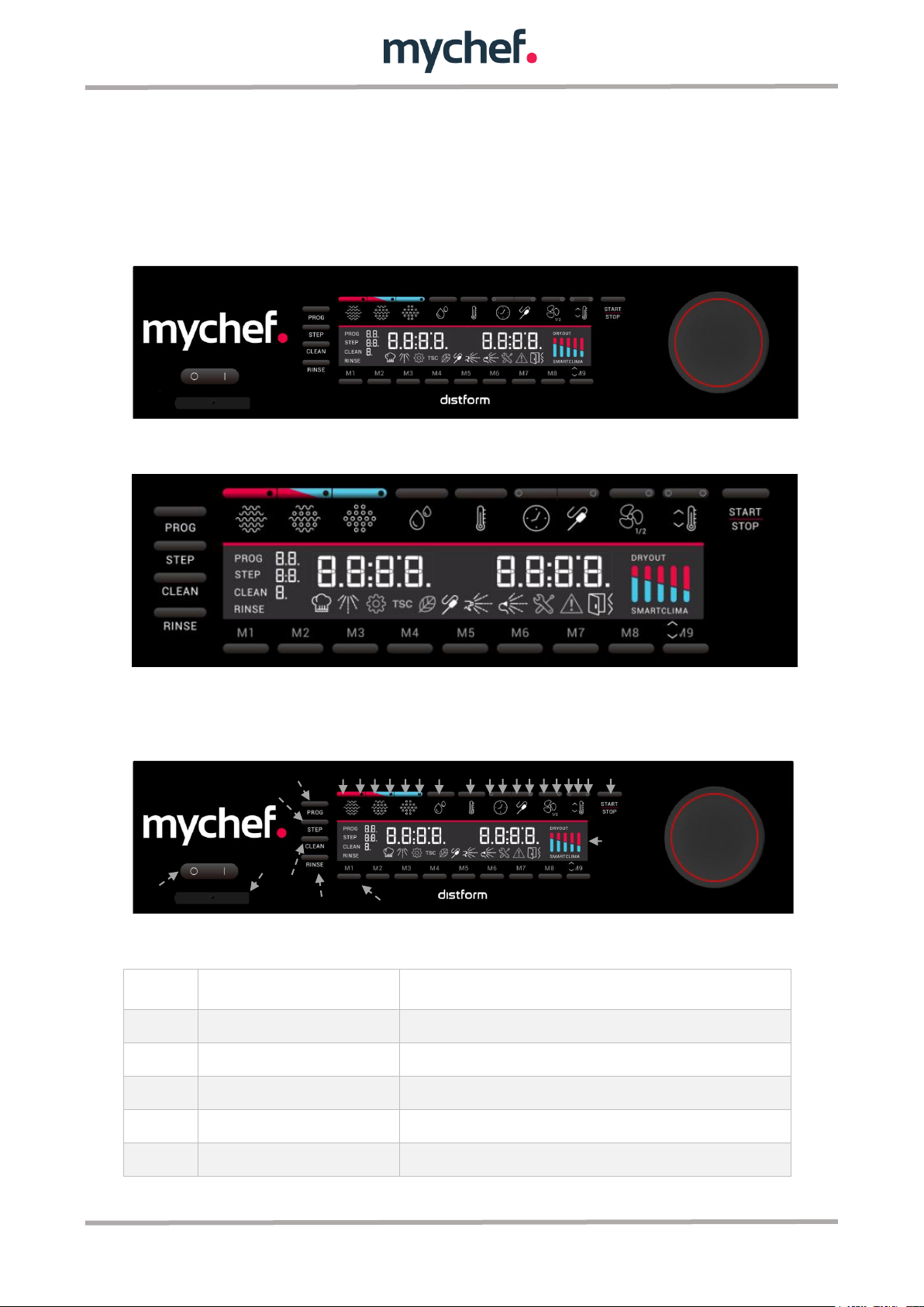
The figure below shows the control panel of a MyChef Concept oven. It consists of a
central LCD screen with different elements such as displays and icons, buttons, a
rotary knob and visual indicators of different colours.
Figure 1. Control panel.
Figure 2. Control panel detail.
The functionality of each of them is explained below:
Figure 3: Control panel description.
7
F
Rinse button RINSE
Convection mode selection button.
G
Convection button
Select the selected mode.
H
Convection mode indicator
Mixed mode selection button.
I
Mixed button for convection and
steam
Select the selected mode.
J
Mixed mode indicator
Steam mode selection button.
K
Steam button
Select the selected mode.
L
Steam mode indicator
Moisture percentage selection button. Only active in mixed mode.
M
Moisture button
Temperature selection button. In operation, the temperature can be
displayed by pressing this button.
N
Temperature button
Indicates the time firing selection.
O
Time indicator
Time selection button.
P
Time button
Convection mode selection button.
Q
Core probe temperature button
Select the heart probe cooking mode by pressing briefly.
Allows the core probe temperature to be read when performing a
long press.
R
Core probe indicator
Indicates the heart probe firing selection.
S
Fan speed button
Fan speed selection button. Each press changes the speed. There
are three speeds: maximum and reduced, and pressed.
The reduced speed is automatically selected at low temperatures.
The pulsed speed is automatically selected at very low
temperatures.
T
Fan speed indicator
Indicates whether the convection fan is at reduced speed, either
pressed or continues. If it is turned off the speed of the convection
fan will be maximum.
U
Cooling indicator
Indicates that cooling will take place or is taking place. If the
indicator flashes, cooling will take place when the temperature
adjustment button is pressed. If it is fixed, cooling is being carried
out.
V
Temperature adjustment knob
(preheating or cooling)
Allows you to start cooking with a cooling or preheating cycle
depending on the current chamber temperature and the desired
cooking temperature.
W
Preheating indicator
Indicates that a preheating is being or will be performed. If the
indicator flashes, a preheating will take place when the temperature
adjustment button is pressed. If it is fixed, this preheating is being
carried out.
X
START/STOP button
Oven start/stop button.
If the oven is on but not cooking, pressing lightly will start the
cooking cycle.
If the oven is on and cooking, pressing lightly will cancel the cooking
cycle.
8
Y
LCD display
LCD screen containing all the icons and displays needed to show
the status and allow user interaction with the oven.
Z
Rotary control
Used to edit values and navigate through the configuration menus.
It also has a multi-coloured LED display, which indicates the status
of the oven. For more information, see chapter 2.1.2.
A1
Memory Location Buttons
Each button is a quick memory location where a program or wash
cycle can be stored by long press. To start the stored program,
press slightly.
Icon
Function
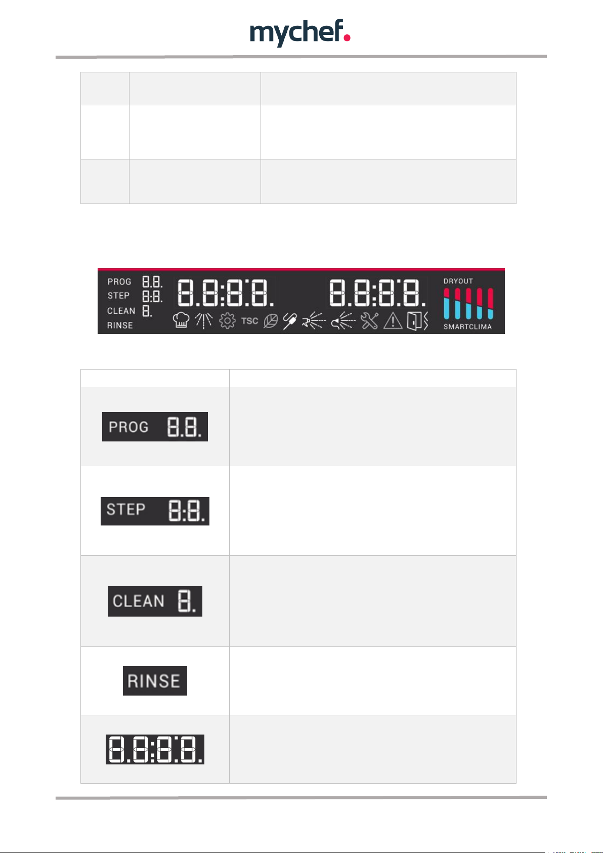
This icon shows the selected cooking program, the digits on the left show
the program number; 1,2,... 99. The flashing PROG icon indicates that the
program is being edited and shows the two digits. By contrast, if the digits
are held steady and flashing, the program is being selected and it is possible
to navigate through the programs using the rotary knob.
This icon shows the firing phases of the programs. The first digit shows the
phase in which you are while the second digit shows the total number of
phases. Like the previous icon, if the STEP icon flashes, the firing phase
indicated in the first digit is being configured. However, if the digits are
flashing and the icon remains fixed, it is possible to navigate through the
different phases using the rotary knob.
This icon shows the 4 self-cleaning programs of the oven. The digit shows
the program number and blinking indicates that you can navigate through the
various cleaning programs with the rotary knob.
If the oven does not have self-cleaning, there is only one manual program
with cleaning assistance.
This icon shows that the rinse program of the oven chamber has been
selected.
If the oven is not self-cleaning, there is no such function.
There are two displays of this type. Both display temperature and time
values as well as other keywords that define the oven's behaviour. In normal
operating mode, the display on the left of the control indicates the
temperature set for cooking. The one on the right shows the remaining time
if a time firing has been chosen or the core probe temperature if a core
Table 1: Panel Control description.
The LCD display is a very important part of the oven interface. The meaning and
usefulness of each icon is explained below:
Figure 4: LCD screen.
9
temperature firing has been chosen.
This icon indicates that cooking has started.
This icon indicates that an automatic or assisted manual cleaning cycle is
being performed.
This icon marks the setting mode. Allows you to display and edit the oven
configuration parameters.
This icon illuminates whenever the TSC, Thermal Stability Control, is
activated.
When this icon illuminates, the oven is in ECO mode. In this mode the oven
consumes a fraction of its usual power. The ECO mode is automatically
activated in situations where the oven requires little power, and
automatically deactivated in situations where full power is required.
This icon flashes when the oven does not detect any connected probe and
needs it to start or continue a firing cycle. If the probe is connected, the icon
will remain fixed when, without being in the firing process, the desired core
temperature is lower than the temperature read by the probe.
This icon lights up during the assisted manual cleaning process of the
camera. When this icon is lit and blinking, it indicates that liquid with
detergent must be introduced into the interior of the camera using a spray
gun.
This icon lights up during the manual cleaning process assisted by the
camera after the previous one. When this icon turns on and blinks, it
indicates that the shower faucet must be inserted into the interior of the
camera and rinsed.
This is the error icon. Lights up when an error occurs and is accompanied by
the error number on the right display.
This is the alarm icon. Lights up when an alarm occurs and is accompanied
by the alarm number on the right display.
This icon indicates if the door is open. The icon illuminates whenever the
oven door is not closed regardless of the operating moment.
10
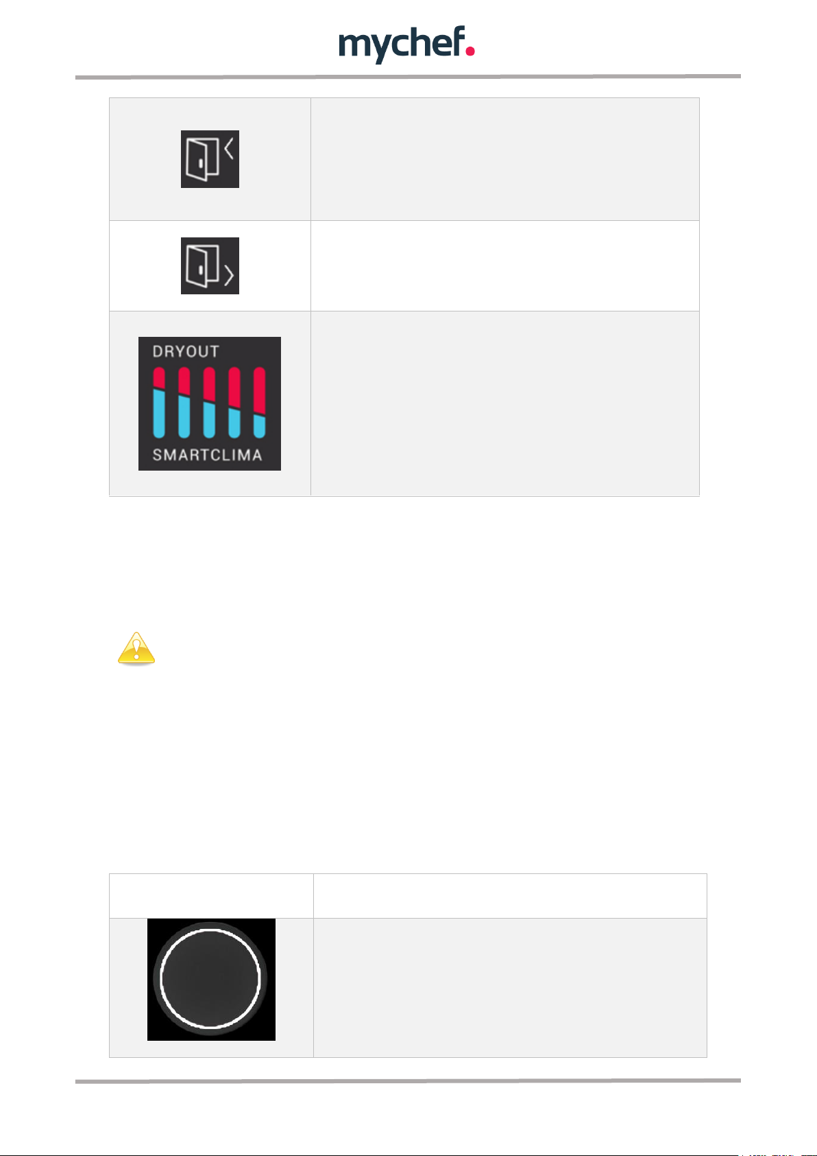
This icon indicates that the oven needs to be charged to continue the firing
cycle. When it turns on and flashes, the door must be opened and charged to
continue.
If a self-cleaning process is being performed, the icon indicates that the
detergent tablet must be inserted into the camera.
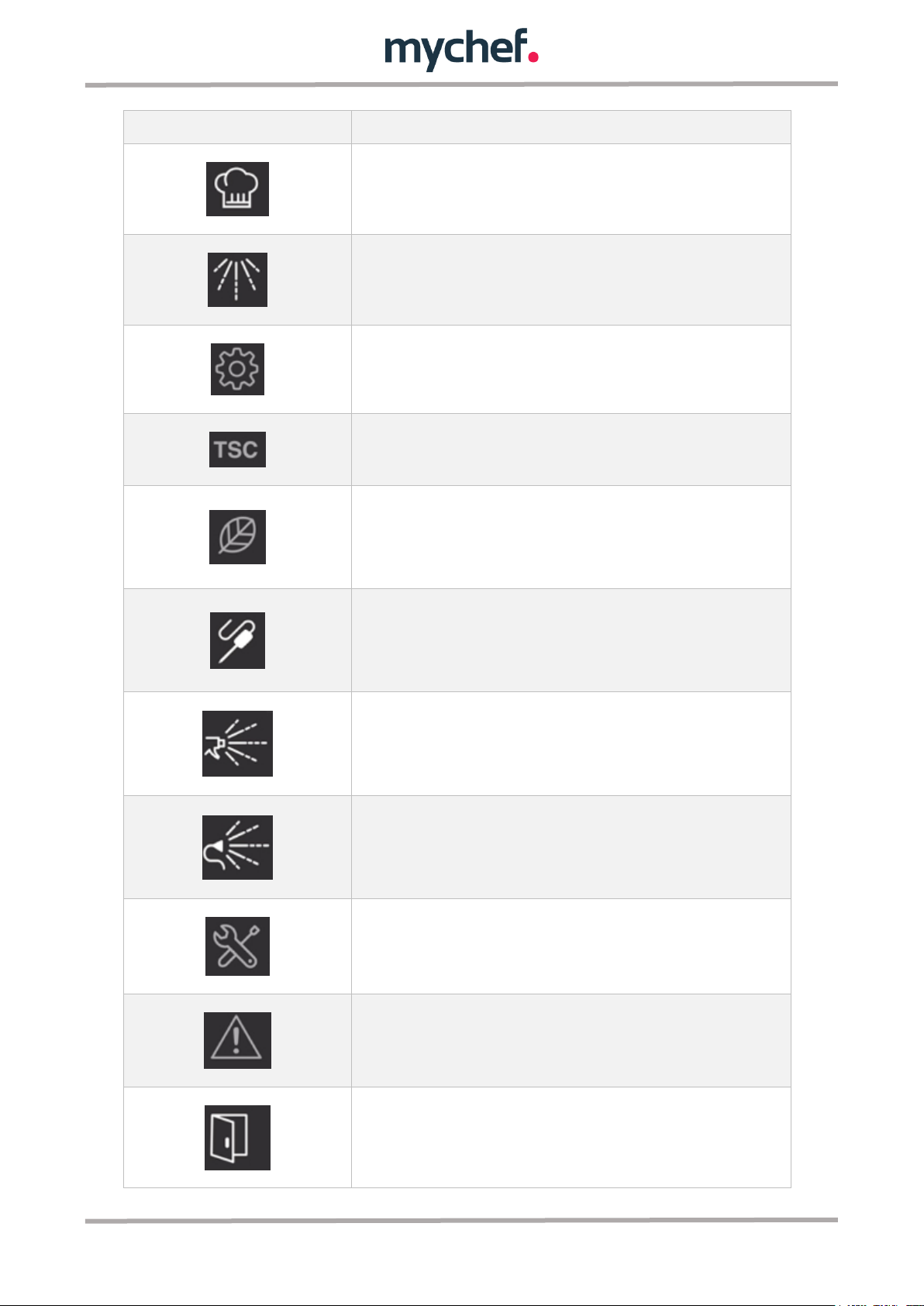
This icon indicates that a cooking process may be finished. When it comes
on and blinks, open the door and unload the trays with the cooked products.
This icon is used to indicate humidity inside the camera.
The DRYOUT icon is associated with the red icons at the top of the graph.
These icons indicate the degree of moisture removal in the camera. There
are five levels and grow from left to right illuminating one more bar each
time a level is raised.
Similarly, the SMARTCLIMA icon and blue bars indicate the degree of steam
generation. In this case they increase from right to left to maintain the same
representation model.
In order to protect the oven from possible overheating, some protective
elements may work even if the oven is switched off. When the oven is at a
safe temperature, they will turn off automatically.
Mode
Temperature
This colour indicates that the oven is not cooking or
cleaning. The oven's not working.
Table 2: Description of LCD display icons.
2.1.1 Switching on the equipment
The equipment is turned on or off using a switch on the control panel to the left of the
panel.
2.1.2 Rotary knob LED indicator
The rotary knob has an illuminated circle indicating the operating status of the oven.
This indicator changes colour depending on the state of the oven, allowing the user to
check easily and quickly and even while at a certain distance from the oven if a process
has been completed, etc.
The possible colours of the indicator and their meaning are given below:
11
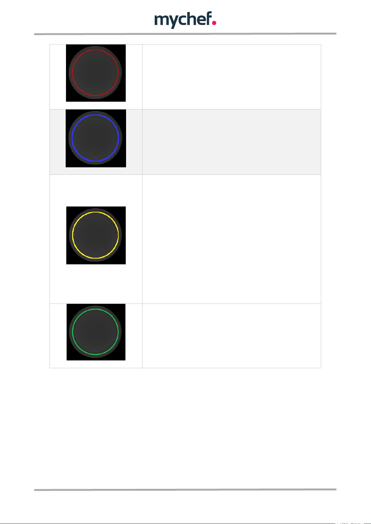
This colour indicates that you are cooking.
This colour indicates that a cleaning or rinsing process
is in progress.
This colour has three different meanings.
If the oven is cooking or washing, it indicates that the
cooking is about to end: if there is 1 minute left to finish
a time cooking or cleaning process, or, if a probe
cooking is taking place, it will light up when 5ºC is
missing for the final temperature.
It also indicates whether the oven is performing a
temperature setting process, both preheating and
cooling.
Finally, it is also used to indicate that the oven is in
setup mode.
This colour indicates that a cooking or cleaning process
is complete.
Table 2: Colour description rotary knob.
2.1.3 Cooking programs
There are 99 programs that can be edited and retrieved at will. All of them can have up
to 5 cooking phases.
There is also a manual mode that allows you to modify the cooking parameters
(camera temperature, humidity, time, etc.) without saving them in any program. This
manual mode is displayed as "PROG -" in program selection.
In user programs, it is possible to change any cooking parameters (temperature,
humidity, time, cooking mode, etc.). To do this, press the button corresponding to the
parameter to be modified and adjust the parameter value by turning the rotary knob.
12
When you change any parameters of the user programs, the manual program
is automatically selected to avoid modifying the data of the original program.
For example, pressing the humidity button defined in Table 1 will flash the moisture
display and you can adjust the humidity level.
To leave a program in continuous mode, press the time button and turn the rotary knob
counter clockwise until "Cont" appears on the time display.
There are several safety measures that prevent abnormal operation of the equipment,
of which the user must be aware during use.
In case of any error, the unit will stop and display its code (see chapter 1.6).
The oven will not operate if the door is open.
2.1.4 Cooking mode
There are three cooking modes: convection, mixed and steam. To select a particular
mode, click on the corresponding button.
Figure 5: Cooking mode selectors.
The convection mode acts as a forced convection oven without adding or removing
moisture from the firing chamber.
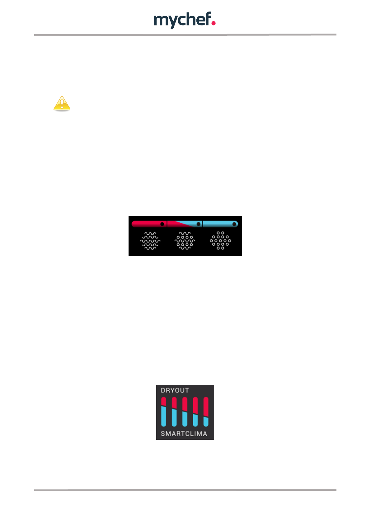
The combi convection mode enables intelligent, oven-controlled regulation of moisture
removal or moisture input in the cooking chamber. To do this, press the humidity
button and turn the knob to the desired value. This value is shown through the graphic
that appears in the following image, allowing 11 values; 5 for humidity contribution to
the firing chamber (the blue inferior bars labelled SMARTCLIMA, intelligent control of
water injection), 5 for humidity extraction (the upper bars labelled SMARTCLIMA red
with DRYOUT, intelligent control of humidity extraction) and a neutral value (all graphic
off).
Figure 6: Humidity setting in mixed mode.
The steam mode saturates the cooking chamber with moisture.
13

Mode
Icon
Temperature
Humidity
Convection
30 a 300ºC
0%
Mixed
30 a 300ºC
-100 a 100%, in
leaps of 20%
Steam
30 a 130ºC
100%
In order to prolong the life of your oven, it may automatically reduce the
maximum cooking chamber temperature.
The table below summarizes the characteristics of each of them.
Table 4: Cooking modes in MyChef ovens.
In all cooking modes it is possible to humidify the chamber at will. To do this, press the
HUMIDITY button until the blue humidity graph bars on the left side of the LCD display
light up. In the case of steam cooking, the SMARTCLIMA icon disappears and
intelligent humidity control is deactivated by passing the steam injection control to the
user.
14

2.1.5 Cooking control
2.1.5.1 Cooking by temperature and time control
The temperature and time control mode is the simplest, we simply choose a
temperature and time by rotating the circular knob after pressing the TEMPERATURE
and TIME buttons respectively.
When the START/STOP button is pressed, the oven will start heating the chamber and
stop after the set time has elapsed. At this point, the timer will display the keyword
"End", the oven will beep for one second and the door opening icon will light up until the
user finishes cooking by slightly pressing the START/STOP button.
Example of cooking at 90º for 10 minutes:
Figure 7: Example. Cooking 90ºC in steam mode for 10
minutes.
Figure 7: Oven temperature.
2.1.5.2 Temperature cooking and time control with temperature adjustment
The temperature and time firing control mode with temperature setting is very similar
to the previous method. In this mode the oven automatically brings the temperature in
the chamber to the value selected by the user so that when the opening and loading of
15

the feed occurs, therefore the start of cooking, the temperature in the chamber is equal
to the selected one. The oven automatically calculates the ambient temperature in the
chamber and decides whether a heating or cooling process should be carried out
depending on the desired value.
To use this mode, as in the previous case, we choose the temperature and cooking
time by pressing the TEMPERATURE and TIME buttons respectively. This time, instead
of pressing the "START/STOP" button to start the process, press the SETUP key.
This key has two small visual indicators to the left and right, one blue and one red.
Depending on the light that comes on, a cooling (blue) or preheating (red) will be
carried out.
Before cooking begins, the process indicator for the required process according to the
temperature of the chamber will blink indicating that pressing the button initiates a
preheating or cooling process. When pressed, the indicator will stop flashing and will
remain permanently lit indicating that the process has started.
You can cancel the preheating and continue cooking by pressing the START/STOP
button.
Once the oven reaches preheating temperature, it will indicate to the user that the oven
can be charged by an audible and visual warning: the door opening icon will light up
and the charge arrow will flash.
To avoid excessive overheating, this state is maintained for a maximum of ten minutes.
When you open the door and load the oven, the preheating program will end and the
firing program will be executed.
Example of cooking at 90º for 10 minutes with preheating:
Figure 9: Example. Cooking 90ºC in steam mode for 10 minutes.
16

Figure 8: Oven temperature.
2.1.5.3 Temperature cooking and core probe control
The core probe controlled temperature control mode terminates cooking when the
temperature in the food core is equal to the selected temperature. The chamber
temperature is kept constant and equal to the value selected on the temperature
display.
To use this mode, select a chamber temperature and a desired temperature at the
heart of the food by pressing the TEMPERATURE and PROBE buttons respectively and
adjusting them with the rotary knob. When the START/STOP button is pressed, the
oven will start to warm up and stop when the core probe temperature is equal to the
setpoint temperature of the probe. At this point, the timer will mark "End" until the user
finishes cooking by briefly pressing the START/STOP button.
If the probe is not connected, the oven will indicate this by means of the corresponding
icon flashing, and acoustically. In this case, connect the probe and press START/STOP.
If the probe is connected, and the probe reading is higher than the desired temperature,
the probe icon will remain fixed and cooking cannot begin. Decrease the temperature
at the probe, or change the desired end temperature.
Figur3 9: Probe icon.
17

For this cooking mode, the multipoint probe or the sous-vide probe must be
connected.
If we try to start a heart-probe-controlled program, and it is not connected,
the oven will sound and visually warn and the program will not start.
When the oven is in the process of cooking controlled through a core probe,
the chamber temperature display shows the temperature to be reached in
the chamber, and the core probe display shows the actual temperature of the
food.
Example of cooking at 90º until the temperature in the heart of the food is
55º:
Figure 12: Example. Cooking 90ºC in steam mode and core temperature 55ºC.
Figure 13: Oven temperature (blue) and core probe (yellow).
If we are performing a core probe controlled cooking cycle, the time/sound display will
indicate the actual probe temperature. By pressing the PROBE button, the display for
the probe will indicate the desired core probe temperature and can be modified by
rotating the encoder if desired.
2.1.6 Programs edition
Programs 1 to 99 can be modified by pressing the PROG button for a few seconds after
the program to be edited has been selected by rotating the knob. When an acoustic
signal sounds and the "PROG" icon to the right of the LCD flashes, the firing parameters
can be edited.
18

The first number in the phase indicator indicates the current phase and the
second number indicates the total of existing phases.
To add or remove phases in programs 1 to 99 before, enter program editing
mode.
If we are editing a program that has not been saved, the temperature and other values
will appear empty in the display screens and the LEDs will guide us to define all
cooking parameters. The indicator will blink along with the segments of the display
that represent the value associated with each parameter.
If we are editing an already stored program, the values will be set and the indicators will
show the parameters of the program. When selecting a parameter by pressing the
corresponding button, the segments associated with it will blink and the value can be
changed using the knob.
In any case we can edit the cooking mode, chamber temperature, humidity in combined
mode, cooking time or probe temperature depending on the selected end condition and
fan speed.
To save the program after this process is complete, press the PROG button until the
acoustic signal sounds again and the program number stops flashing.
2.1.7 Step Edition
The editing of the phases can be done directly in the manual program (---) or phases
can be added to the user programs. If you want to modify the phases in any user
program (programs 1 to 99), you must first enter the program editing mode of that
program. The editing process follows the same pattern as before using the flashing
segments and indicators to edit the parameters of each phase.
Navigation between steps
To navigate between the various phases, press the STEP key slightly. The digits to the
right of the STEP icon showing the current phase and the total number of existing
phases will flash and can be skipped from phase to phase using the rotary knob.
2.1.7.1 Add a Step
To add a step, enter the program editing mode. If the program has only one phase, the
program icon will blink and pressing the STEP button will add a new phase. If the
program already contained more than one phase, press the STEP button to navigate
through them until you reach the last one. At this point, pressing it again will add one
more phase. After adding all desired phases, press the PROG button for a few seconds
until the acoustic signal indicates that all changes have been saved.
Once a phase has been added, the firing parameters of the phase can be modified as
specified in the previous subchapters.
19

2.1.7.2 Delete
To delete a phase, enter program editing mode. Briefly pressing the STEP button will
take you from one phase to the next until you want to delete it. This will be deleted by
pressing the "Convection”, “Combined" or "Steam" button (depending on the mode
selected in the previous phase) whose light indicator will flash. Pressing it will erase
the current step and all subsequent steps allowing you to complete the program again
from the step you wanted to delete.
An example to clarify this elimination process would be to delete the second phase of a
three-phase program. To start, press and hold the PROG button with the selected
program until you enter edit mode. The STEP button should then be pressed to
navigate from the first phase to the second. At this point, press the convection button
that would blink in the upper left corner of the panel (since the second phase is
supposed to be a convection phase in the example) removing all values from step 2
and step 3 altogether.
2.1.8 Starting the cooking cycle
Once the cooking parameters have been selected, either manually or in a specific
program, we can start the process.
To do this, press the START/STOP key, and its indicator on the LCD will light up.
Figure 10: cooking indicator
2.1.9 End of step
At the end of a cooking cycle, the equipment visually and acoustically signals this
state. Specifically:
- The visual indicator on the rotary knob lights up in green
- 3 beeps of 2 seconds are emitted, with an interval of 10 seconds.
- The keyword "End" appears on the time/sound display of the LCD display until
the user finishes cooking.
To finish cooking, press START/STOP.
2.1.10 Fast cooling
Rapid cooling is a particular use of the temperature setting mode (preheating or
cooling) explained above. If a quick cooling process is desired, the preheating or
cooling firing start mode must be used. To do this, select a low temperature value in
manual mode, e. g. 30°C or "Off", and press the SET button.
In this mode the convection fan is switched on and the resistors are switched off. In
this particular case, even if the oven door is opened, the process will not stop and the
20

Note that in this mode, the convection fan works when the door is open.
Take appropriate precautions.
In order to be able to regulate the temperature in the chamber correctly, in
certain situations (low temperature, etc.) the oven can automatically select
the reduced convection speed.
Set the oven date and time when recording HACCP data.
fan will continue to rotate. This way, and with the door open, the temperature of the
chamber can be lowered in a few seconds.
Once in this mode, the display for the camera probe shows the temperature of the
camera probe continuously. To exit the quench mode, briefly press START/STOP.
2.1.11 Speed selection
In any cooking mode, the user can select the speed of the convection fan that best
suits his needs. To do this, press the fan speed button.
If the speed indicator is off, the oven will operate at maximum convection speed. If, on
the other hand, it is switched on, the oven will rotate the convection fan at a reduced
speed.
Figure 15: Maximum and reduced speed.
The fan has 3 operating speeds. Low speed with pulsed operation, low without pulsed
and high operation. The first one is only used for temperatures below 40ºC, the second
one only for temperatures above 40ºC and the last one for temperatures above 60ºC.
2.1.12 HACCP data recording
The equipment allows the recording of temperatures and events occurring during
normal use. To record data, insert a memory into the USB connector in the lower right
corner of the oven.
Figure 16: USB connector housing.
This data can be retrieved using the HACCPManager software (optional). They can also
be viewed from a computer.
21

For the use of the washing processes in as much as for the handling of the
products used in the process, appropriate protections must be used.
Figure 11: HACCPManager.
2.2 Cleaning the cooking chamber
Depending on the oven model, there are two types of processes for cleaning the firing
chamber: manual assisted and automatic.
The assisted manual programs are predefined in ovens that do not have a self-cleaning
system. Those that do have this system have predefined the different automatic
programs.
You can change the cleaning type by accessing the configuration parameters.
2.2.1 Manually assisted cleaning
This chapter applies only to ovens without self-cleaning system (optional).
Before manual cleaning, make sure you have all the necessary equipment. This
material can be purchased from your local mychef dealer.
- Cleaning shower
- Spray gun for spraying cleaning products
- Distform DA21, detergent liquid and brightener in one, or equivalent:
Combination of substances, including:
o potassium hydroxide 10 - <25%
o Complex mixture of glycols, sequestrants, surfactants and alkalis.
o Physical appearance: Oily liquid
22

When the appliance is in operation, open the door slowly and carefully to
avoid possible burns from the steam or hot air that may come out of the
cooking chamber.
o Density 1.1 gr/cc. approx.
o pH: >13
Then remove any solid food scraps/rests that may be inside the chamber manually. Do
not use the manual shower faucet accessory to remove food scraps from the cooking
chamber, remove them beforehand and prevent them from coming out of the drain. Do
not place trays or grills during the washing process. It should always be carried out
without load, to ensure proper cleaning of the equipment.
Once this is done, the assisted manual cleaning process can be started. To start the
process press the CLEAN button and then press the START/STOP button to start the
process.
Meanwhile, refill the spray gun with Distform DA21, degreasing liquid and polish in one.
After 20 minutes of starting the semi-automatic cleaning process, the following icon
will illuminate. This indicates that the door must be opened, the chamber sprayed with
the spray gun and the door closed again.
Figure 12: Spraying detergent icon.
At the end of the second phase, after 20 minutes, clean the camera with a cloth to
avoid damaging it. Afterwards, rinse the chamber with the shower faucet until no
detergent remains. The icon below will illuminate to indicate that rinsing is required.
Figure 13: Rinse icon.
The last phase, also 20 minutes, corresponds to a drying of the chamber. If any
moisture remains, wipe the inner chamber dry with a cloth.
2.2.2 Self-Cleaning System
2.2.2.1 Self-cleaning and rinsing programs
Using the MyCare cleaning system makes it possible to automatically clean the
cooking chamber and has 4 wash programmes plus a rinse programme.
23

Automatic cleaning programs are only enabled if the oven is equipped
with this option.
Use MyCare Cleanduo in ovens equipped with automatic washing system,
and DA21 in ovens with manual washing system assisted. The use of other
products voids the warranty.
For the use of the cleaning processes as well as for the handling of the
products used in the process, appropriate protections must be used. Never
touch the detergent with your hands.
Program
Description
Duration
CLEAN 1
ECO self-cleaning program
63 min
CLEAN 2
Self-cleaning program for low dirt level
103 min
CLEAN 3
Self-cleaning program for medium dirt level
143 min
CLEAN 4
Self-cleaning program for high dirt level
183 min
RINSE
Rinse program.
10 min
Before starting any cleaning process, make sure that the water flow to the
unit is open.
Cleaning programs are specifically designed to use MyCare cleanduo detergent. The
special formulation of this product stands out for having twice the concentration of
active product than that of most similar products available on the market. It also
includes a polishing additive for a perfect all-in-one finish. This makes it possible to use
only one MyCare Cleanduo tablet per wash, with the consequent savings and ease of
use.
The time required to carry out each program and the use and usefulness of each
program are listed in the table below.
Table 3: Self-cleaning and rinsing programmes
Before the self-cleaning cycle, remove any solid food scraps/rests that may be inside
the chamber manually. Do not use the manual shower faucet accessory to remove
food scraps from the cooking chamber, remove them beforehand and prevent them
from coming out of the drain. Do not place trays or grills during the washing process. It
should always be carried out without load, to ensure proper cleaning of the equipment.
24

Never place the detergent with the convection fan moving.
The automatic cleaning cycle can then be started. To do this, select one of the cleaning
programs or rinse process on the control panel depending on the dirt in the chamber.
To do this, press the CLEAN button and navigate through all four programs with the
rotary knob. If you want to perform a short rinsing process instead of cleaning, press
the RINSE button.
Before inserting the MyCare CleanDuo tablet, check that the cooking chamber
temperature is not too high. If the blue temperature adjustment indicator blinks, it
indicates that the temperature in the chamber must be lowered before the detergent is
introduced into the chamber. In this case, press the SET button to lower the cooking
chamber temperature.
Figure 20: Setting the required temperature
The oven will begin a cooling process that can be done with the door open to make it
faster.
When the oven indicates this with the corresponding icon, the temperature from which
it is safe to introduce the detergent into the firing chamber has been reached.
Figure 21: Cooling completed. Introduce MyCare detergent.
At this point it is important to stop the fan using the START/STOP button, open the
door and insert the detergent into the dedicated housing. Once entered, close the door
again to start the cleaning program.
If cooling is not required, you can place the MyCare detergent directly in its assigned
space and start the cleaning or rinsing cycle by pressing the START/STOP key.
25

Before starting any cleaning or rinsing process, check that a temperature
adjustment of the cooking chamber is not necessary.
Before starting any cleaning process other than rinsing, make sure that the
detergent tablet has been placed in the oven.
To insert the detergent tablet into the chamber, it is essential to stop the fan.
It is important not to introduce the detergent while it is running in order to
prevent the detergent from being drawn into the air stream and endangering
the health of the user.
The duration of the self-cleaning programs specified in Table 5 does not
take into account any cooling of the chamber.
Never open the door of the cooking chamber during an automatic cleaning
process.
Figure 22: Housing for MyCare detergent.
Once you have started the automatic process do not open the door under any
circumstances, as chemicals used for cleaning and steam may escape. This situation
would pose a significant risk of corrosion and burns.
The process can be stopped in case of emergency with the START/STOP button. In
doing so, the process will stop and the CLEAN and RINSE icons will flash on the screen
to indicate that a button must be pressed to continue.
If we press the CLEAN button the process will resume normally. Pressing the RINSE
button will perform a rinse to remove all chemical residue from the chamber and finish
cleaning. If you press the second key to cancel the cleaning program, it is not
necessary to remove any residue from the tablet that has not dissolved using chemical
26

If the cleaning process has been stopped without the cleaning process being
completed automatically, it is mandatory to remove all undissolved pieces of
detergent tablet from the chamber before proceeding with the final rinse.
Always run a self-cleaning or rinsing program when error 26 occurs.
protective gloves. Open the door, remove all the pieces, close it and then press RINSE
for perfect rinsing.
If at the end of any of the automatic cleaning processes you detect that there are any
detergent residue left in the chamber (even behind the fan cover plate), perform a
rinsing program or perform a thorough manual rinsing of the cooking chamber.
If there is a power failure during the cleaning process, an error message will be
displayed on the control panel (error 26) when the oven is turned on again. In this case,
to prevent detergent and brightener residue from remaining in the chamber, run a rinse
program.
27

2.3 Configuration menu
To access the setup menu, first change the temperature value in the camera to "Off".
Then simultaneously press the CONVECTION and START/STOP button.
Figure 14: Access to the configuration menu.
The following icon will light up when you confirm the entry in the setup menu.
Figure 24: Configuration menu icon
This menu is structured in 6 blocks of registers or parameters that contain all the oven
information from the date and time settings to the firmware or serial number.
To browse through the registers and be able to consult values and edit them, we must
first select the block of registers to which we want to access. Each block is associated
with a memory button: button M1 to block P1, M2 to P2, M3 to P3... Pressing the button
briefly will select the block. Once set, you can navigate between the different registers
using the rotary knob. On the right display of the LCD we will see the value associated
with each register.
Figure 25: Example. Displaying record 00 in block P1
If you want to change any of the editable values, press the PROG button with the record
to be modified selected. The display on the right side of the screen that shows the
register value will blink and by rotating the encoder it will be possible to modify its
value. Pressing the rotary knob will save the value and return to the register selection
28

Block
Register
Name
Parameter
Editable
P1
00
SerialNumber
Serial Number (Thousands)
No
01
SerialNumber
Serial Number (Units)
No
02
FirmwareVersion
Firmware version
Yes
03
FirmwareDefault
Restore default values
04
Lock
Blocking programs
Yes
05
Light
Light timer, in seconds.
Si
06
Reservado
Not used
Si
07
TotalTime
Displays total oven usage hours
Yes
08
EquivalentTime
Displays equivalent hours of oven
use, depending on temperature
Yes
09
USB upload
Records programs from the USB
memory stick to the oven memory.
Yes
10
USB download
Saves programs from the oven
memory to the USB memory stick
Yes
mode by pressing the button associated with the block and scrolling through the
registers with the encoder.
All records are presented below:
2.3.1 Block P1, oven configuration
The parameters of this block contain machine and software identification information
and allow general operating parameters to be configured.
Table 6: Block P1, oven configuration.
2.3.1.1 Firmware Version
Record number 2 "FirmwareVersion" of block P1 indicates the firmware version of the
equipment.
The firmware can also be updated here. To do this, with a FLASH memory connected to
the USB port, press the START/STOP button for a few seconds. The new firmware
must be located in the drive's DISTFORM®MYCHEF®FW folder and be called IMAGE.
HEX.
Figure 26: Location of the new firmware to be loaded.
29

If the FLASH memory is connected, the display shows 0001. If it is not, 0000
will appear.
If the FLASH memory is connected, the display shows 0001. If it is not, 0000
will appear.
Block
Register
Name
Parameter
Editable
P2
00
Year
Date and time setting: Year
Yes
01
Month
Date and time setting: Month
Yes
02
Day
Date and time setting: Day
Yes
2.3.1.2 Firmware Default
Restores factory default values. To do this, enter the configuration mode as explained
at the beginning of the section. Access the first parameter block, find register 3 and
press the START/STOP button. The restoration will start automatically.
All values shall be restored except for the oven type, the number of TSC channels, the
self-cleaning type, the fan type and the statistical values of the oven.
2.3.1.3 Lock
It is possible to lock the programs by accessing register 4 "Lock" of block P1 and
editing the stored value, where 1 is lock and 0 is not lock. This lock prevents the user
from editing the oven programs.
2.3.1.4 Light
The "Light" record number 5 of block P1 shows how long the light will remain on since
any control panel command was last pressed.
This parameter must be set to change the time. If the value is greater than zero, it
indicates the seconds that the light will remain on, up to a maximum of 600. If it is -1,
the light will remain on permanently each time the oven is turned on.
2.3.1.5 USB upload
Loads the programs from a FLASH memory connected to the USB port and records
them in the memory of programs 1 to 99 of the oven. To do this, with a FLASH memory
connected to the USB port, press the START/STOP button for a few seconds.
2.3.1.6 USB download
Record the programs 1 to 99 of the oven in a FLASH memory connected to the USB
port. To do this, with a FLASH memory connected to the USB port, press the
START/STOP button for a few seconds.
2.3.2 Block P2, Date and time
This block allows you to set the time and date.
30

03
Hours
Date and time setting: Hour
Yes
04
Minutes
Date and time setting: Minute
Yes
05
Seconds
Date and time setting: Seconds
Yes
Block
Register
Name
Parameter
Editable
P3
00
Password
Password of the technical service
Yes
01
Type
Oven type
No(SAT)
02
Tsc
Number of TSC channels (0 - 4)
No(SAT)
03
Autoclean
Type of self-cleaning
No(SAT)
04
FanConfig
Fan and inverter type
No(SAT)
05
RelayTest
Relay test relays 1 to 15
No(SAT)
06
GPIOTest
GPIOs Test
No(SAT)
07
TSCTest
TSC test
No(SAT)
08
InverterTest
Inverter test
No(SAT)
09
AutoReverseTemp
Auto-reverse activation
temperature
No(SAT)
10
HysteresisHeating
Temperature hysteresis
No(SAT)
11
LogPeriod
Period between HACCP, in
seconds
No(SAT)
12
AutomaticRecovery
Automatic recovery
No(SAT)
13
SteamVenting
Active ventilation
No(SAT)
14
EncoderSensibility
Encoder sensitivity
No(SAT)
15
SmartClimaSetting
Humidity control settings
No(SAT)
16
RelayRemap
Free relay remapping
No(SAT)
17
ProbeRemap
Probe for temperature control in
chamber
No(SAT)
18
ErrorInhibit
Disable error control
No(SAT)
This function will only continue with cooking in the event of a power failure
and subsequent recovery of the power supply.
Table 7: Block P2, Date and time.
Each register allows you to query and edit values to enter the date and time in the oven.
2.3.3 Block P3, Configuration SAT
This block allows to consult the internal configuration parameters of the oven and
facilitates the diagnosis of faults and malfunctions as well as its solution to the
technical assistance service.
Table 4: Block P3, Configuration SAT.
Parameters report a very wide range of features ranging from the type of oven to fan
configuration, etc. and also allow the service technician to perform tests and tests to
ensure perfect operation.
2.3.3.1 NightWatch
NightWatch allows the oven to automatically continue cooking after a power failure.
This feature is especially useful for unattended cooking.
31

This function can be disabled by your dealer. Make sure that you fully
understand the risks involved.
To minimize risks, analyze the food after such a low temperature warning
when it is automatically recovered from cooking, or discard it (Error 28).
Use the HACCP data record to always check firings. See chapter 2.1.12.
This function is deactivated at the factory and must be activated by your
dealer.
Please note that steam extraction only works in the final moments of
cooking. Therefore, this action does not occur when the oven door is opened
during cooking.
This function will only be activated in time-controlled cooking.
When a cut occurs and the power supply is subsequently restored, the oven recovers
the current firing (if any) and continues it with the same parameters prior to cutting.
If it is not cancelled, the MyChef oven automatically checks the temperature of the
cooking chamber. If the temperature is below 56°C there may be a risk of bacterial
contamination. In this case, the oven will continue cooking but will display error 28
when pressing the START/STOP button to end the firing cycle. In this case, the final
user shall decide the fate of the food, taking into account the risks of possible bacterial
contamination.
2.3.3.2 Automatic steam extraction from the chamber
In order to avoid burns or steam discomfort when opening the door, MyChef ovens can
remove steam from the chamber at the end of the cooking process. Even when in
convection mode, this extraction can be useful to eliminate steam that may be
released from food in the cooking chamber.
When the oven enters the steam extraction process, a large amount of steam can
escape through the chimney, depending on the saturation level. The use of a
condensing hood is recommended for MyChef ovens.
32

Block
Register
Name
Parameter
Editable
P4
00
Probe 1
Multipoint probe. Point 1
Yes
01
Probe 2
Multipoint probe. Point 2
Yes
02
Probe 3
Multipoint probe. Point 3
Yes
03
Probe 4
Multipoint probe. Point 4
Yes
04
Probe 5
Not used
Yes
05
Probe 6
Not used
Yes
06
Probe 7
SmartClimate Probe
Yes
07
Probe 8
Probe Camera
Yes
08
Probe 9
PCB temperature
Yes
09
Probe10
Inverter temperature
Yes
If the temperature of a sensor is higher than 350ºC or lower than -50ºC it
means that the sensor is not connected.
Block
Register
Name
Parameter
Editable
P5
00
T_000_050
Operating hours between 0ºC and
50ºC
No
01
T_050_100
Operating hours between 50ºC and
100ºC
No
02
T_100_150
Operating hours between 100ºC and
150ºC
No
03
T_150_200
Operating hours between 150ºC and
200ºC
No
04
T_200_250
Operating hours between 200ºC and
250ºC
No
05
T_250_300
Operating hours between 250ºC and
300ºC
No
06
Rinse
Number of rinses
No
07
Clean1
Number of cleanings level 1
No
08
Clean2
Number of cleanings level 2
No
09
Clean3
Number of cleanings level 3
No
10
Clean4
Number of cleanings level 4
No
11
Door
Number of door openings divided by
10
No
2.3.4 Block P4, Probe
This block allows you to consult the temperature readings of the oven at different
points.
Table 9: Block P4, Probes.
Each register is associated to a temperature reading point of the oven, allowing to
control different critical points of the oven.
2.3.5 Block P5, Statistics
This block collects statistical values of the oven's operation, allowing to obtain trends
and graphs that allow Distform to improve its products and adapt them to the user's
needs.
Table 5: Block P5, Statistics.
33

Block
Register
Name
Parameter
Editable
P6
00
Error 0
Last error occurred
No
01
Error 1
Penultimate error occurred
No
02
Error 2
First to last mistake made
No
03
Error 3
Previous to Error 2
No
04
Error 4
Previous to Error 3
No
05
Error 5
Previous to Error 4
No
06
Error 6
Previous to Error 5
No
07
Error 7
Previous to Error 6
No
Figure 15: Alarm icon.
Figure 16: Error icon.
Error
Internal definition
Details
0
NO ERROR
Without error
1
ERROR GENERAL PURPOSE INPUT
General error entry. Not used.
2
ERROR OVERTEMPERATURE
General temperature input. Not used.
3
ERROR OVERTEMPERATURE PCB
Over temperature PCB. Check that the cooling fans of the
electronics are working properly, that there is sufficient space
between the rear and the wall, and that the ambient temperature
is not excessive.
4
ERROR COMMUNICATION
Plate communication is not responding. Check the cable
connecting the power board and control board.
5
ERROR EEPROM
The communication processor and EEPROM do not work. Check
the control card.
6
ERROR MOTOR
Motor/inverter error. Check motor wiring.
These statistical records primarily store values of operating time, cycle repetition, and
the rate of use and wear of certain elements to monitor the useful life and maximize
the efficiency of all oven components.
2.3.6 Block P6, Errors
This block is a record of the last 7 errors that have occurred during the operation of the
oven.
Table 11: Block P6, Errors.
2.4 Errors y alarms
Errors and alarms can occur during the preparation and execution of any of the
programs available in the oven. If this is the case, the LCD will show the alarm or error
icon and the right display will show the error or alarm code.
The table below shows the different errors and alarms, as well as possible solutions to
them.
34

7
ALARM WATER
No water detected. Make sure that the water supply is connected
correctly.
8
ERROR WASHING
No detergent/brightener detected. Not used.
9
ERROR PROBE1 TEMP SENSOR NOT
CONNECTED
External probe not connected. Check the external probe and
connector.
10
ERROR PROBE1 TEMP SENSOR SHORTED
External short-circuited probe. Check the external probe and
connector.
11
ERROR PROBE2 TEMP SENSOR NOT
CONNECTED
External probe not connected. Check the external probe and
connector.
12
ERROR PROBE2 TEMP SENSOR SHORTED
External short-circuited probe. Check the external probe and
connector.
13
ERROR PROBE3 TEMP SENSOR NOT
CONNECTED
External probe not connected. Check the external probe and
connector.
14
ERROR PROBE3 TEMP SENSOR SHORTED
External short-circuited probe. Check the external probe and
connector.
15
ERROR PROBE4 TEMP SENSOR NOT
CONNECTED
Reserved. Not used.
16
ERROR PROBE4 TEMP SENSOR SHORTED
Reserved. Not used.
17
ERROR PROBE5 TEMP SENSOR NOT
CONNECTED
Reserved. Not used.
18
ERROR PROBE5 TEMP SENSOR SHORTED
Reserved. Not used.
19
ERROR PROBE6 TEMP SENSOR NOT
CONNECTED
Reserved. Not used.
20
ERROR PROBE6 TEMP SENSOR SHORTED
Reserved. Not used.
21
ERROR PROBE7 TEMP SENSOR NOT
CONNECTED
Reserved. Not used.
22
ERROR PROBE7 TEMP SENSOR SHORTED
Reserved. Not used.
23
ERROR PROBE8 TEMP SENSOR NOT
CONNECTED
Camera probe not connected. Check probe and wiring.
24
ERROR PROBE8 TEMP SENSOR SHORTED
Short circuit camera probe. Check probe and wiring.
25
ERROR PROGRAM NOT TERMINATED
Reserved. Not used.
26
ERROR CLEANING PROGRAM NOT
TERMINATED
The oven has been switched off by running a self-cleaning
program. Make a rinse.
27
ERROR CLEANING TEMPERATURE TOO
HOT
The temperature of the oven during a self-cleaning program has
risen above a maximum temperature.
28
ALARM RECOVERY TEMP TOO LOW
The oven has recovered from a power outage, and the
temperature in the chamber was below 56ºC (NightWatch). Risk
of bacterial contamination. Discard or test the product.
Table 12: Errors, alarms and possible solutions.
35

Always run a self-cleaning or rinsing program when Error 26 occurs.
36
 Loading...