

MyBinding Standard APC45 Programmable Instruction Manual

Instruction Manual
Provided By
http://www.MyBinding.com
http://www.MyBindingBlog.com
Standard APC45
Programmable
Paper Cutter


I
• This manual is designed to help you to install, operate and maintain the APC-45 Paper
Cutter. Please read and understand this manual, and keep it in a safe and convenient
place.
• Do not operate the APC-45 until you read and understand the instructions in this
manual.
• Horizon International Inc. shall not be liable for incidental consequential damages
resulting from: improper or inadequate maintenance by the customer unauthorized
modification or misuse, or operation outside of the environmental specifications for the
product.
• Horizon International Inc. pursues a policy of continuing improvement in design and
performance of the product. Therefore, the product design and specifications are
subject to change without prior notice and without our legal obligation.
• All rights are reserved. No part of this manual may be photocopied, reproduced or
translated to another language without the prior written consent of Horizon
International Inc.
Important Information
081208/APC45/06E/NO/HF/KY/F7/I9/P7
UM204023-06
P
APER CUTTE
RPAPER CUTTER
APC- 45
II
Horizon International Inc. cannot anticipate every possible situation that might involve a
potential hazard. The instructions in this manual and warning labels on the machine are
therefore not all inclusive.
All equipment shall be locked out or tagged out to protect against accidental or inadvertent
operation when such operation could cause injury to personnel. Do not attempt to operate
any switch, valve, or other energy isolating device where it is locked or tagged out.
Do not operate the machines when any covers are removed.
Some of the drawings in this manual show the machine with the covers removed to
explain some of the details inside the machine. Never operate the machine with the covers
removed.
Safety Precautions
Safety precautions are indicated in this manual as follows:
The term WARNING indicates a potentially hazardous situation which, if not
avoided, could result in death or serious injury.
The term CAUTION indicates a potentially hazardous situation which, if not
avoided, may result in serious injury, or damage to the machine.
This symbol indicates a note which includes important information. Follow
the note to operate the machine safely.
This symbol indicates a prohibited action. Do not perform any prohibited
action.
This symbol indicates an essential procedure. Follow the procedure to
operate the machine safely.
Important
• This lists the range of acceptable values and operating
conditions.
Attention
• This information will help you to avoid problems with the
machine or help you learn how to operate the machine.
Note
• Refer to this note when you operate the machine.
Additional
Information
• This explains a mechanism in the machine.
III
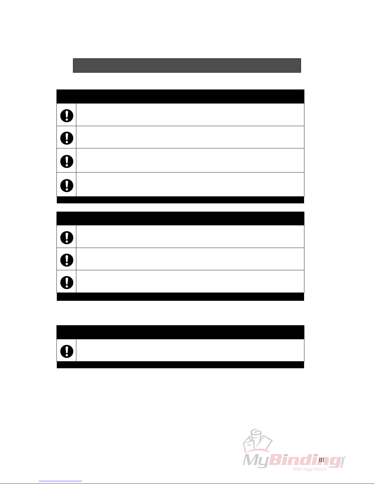
Safety Operation Precautions
WARNING for Operation
This machine must be operated by just one person at a time.
Various safety devices are installed on this machine. If any of these are bypassed or
removed, this may cause severe accident and personal injury.
Each operator should be familiar with the safety instructions, be aware of the potential
dangers, and have sufficient knowledge of how to manage an accident. Anyone who
does not have this training should not operate the machine.
Before starting the machine, be sure to perform the checks described in Chapter 2:
Safety Checks. When loading the sheets on the table and setting the sheet position, get
your foot off from the foot pedal.
CAUTION for Operation
Do not cut anything besides paper. This may damage the machine.
If you turn the power switch Off, wait 10 seconds or more before turning it On again.
Do not get on, or step on the foot pedal with great force. The machine may be damaged.
CAUTION for Maintenance
Do not apply too much grease. Filled grease may stain the paper.

IV
Space Required for Installation
As the electrical parts are installed on the lower left of the machine, repair work may be done from the
right side. Allow about 600 to 700 mm (23.7 to 27.6") on the left side of the machine if it is possible.
In addition, when you adjust the knife angle, you need to insert the tool into the machine from the left
side. Allow about 200 mm (7.9”) on the left side.
Allow about 100 to 200 mm (4 to 7.9”) on the right side and the rear.
Antivibration Cushion
If you use the antivibration cushions, place the cushions under the four corners of the machine. In addition, place the supplied wedges under the machine to keep the machine in a horizontal position.
CAUTION for Installation
Ground Terminal
Make sure to connect
the accessory ground
wire.
If the ground wire is
not connected, the letters on the guide window may not appear
correctly.
Make sure to connect the ground wire.
770 (30.4")
880 (34.7")
100 - 200
(4" - 7.9")
100 - 200
(4" - 7.9")
600 - 700
(23.7" - 27.6")
mm (inch)
Front

V
CONTENTS
Important Information........................................................................................ I
Safety Precautions............................................................................................ II
Safety Operation Precautions......................................................................... III
1. Machine Descriptions .................................................................................. 1
1-1 Machine Descriptions .............................................................................................1
1-2 Control Panel Descriptions .....................................................................................2
1-3 Cutting Mechanism ................................................................................................3
2. Safety Checks ............................................................................................... 5
2-1 Check the Power Switch ........................................................................................5
2-2 Check the Cutting Buttons .....................................................................................7
2-3 Check the Beam Light Sensors ..............................................................................8
2-4 Check the Control Panel ........................................................................................9
2-5 Check the Foot Pedal ...........................................................................................10
3. Operation Procedures ............................................................................... 11
3-1 Cutting Operation on the Cutting Line ..................................................................11
3-2 Cutting Operation by Entering a Value ................................................................. 14
3-3 Cutting Operation by Programmed Value ............................................................17
3-4 Function Cutting ...................................................................................................20
3-5 Compression Operation ....................................................................................... 22
3-6 Creating a Cutting Program .................................................................................23
3-7 Checking the Counter ..........................................................................................30
3-8 Knife Replacement Message ...............................................................................31
4. Replacement and Adjustment.................................................................... 33
4-1 Knife Lower Limit Adjustment ............................................................................... 33
4-2 Knife Angle Adjustment ........................................................................................35
4-3 Cutting Stick Replacement ...................................................................................37
5. Troubleshooting.......................................................................................... 39
5-1 An Error Message Appears ..................................................................................39
5-2 Problems and Remedies ......................................................................................40
5-2-1 Stain, Diagonal Line, Pressing Mark and Uncut of the Sheets ............................... 40
6. Maintenance ................................................................................................ 43
6-1 Lubrication ............................................................................................................43
7. Appendix...................................................................................................... 45
7-1 Specifications .......................................................................................................45
7-2 Accessories ..........................................................................................................46

VI
This page is intentionally left blank.
1
Machine Descriptions
Machine
Descriptions
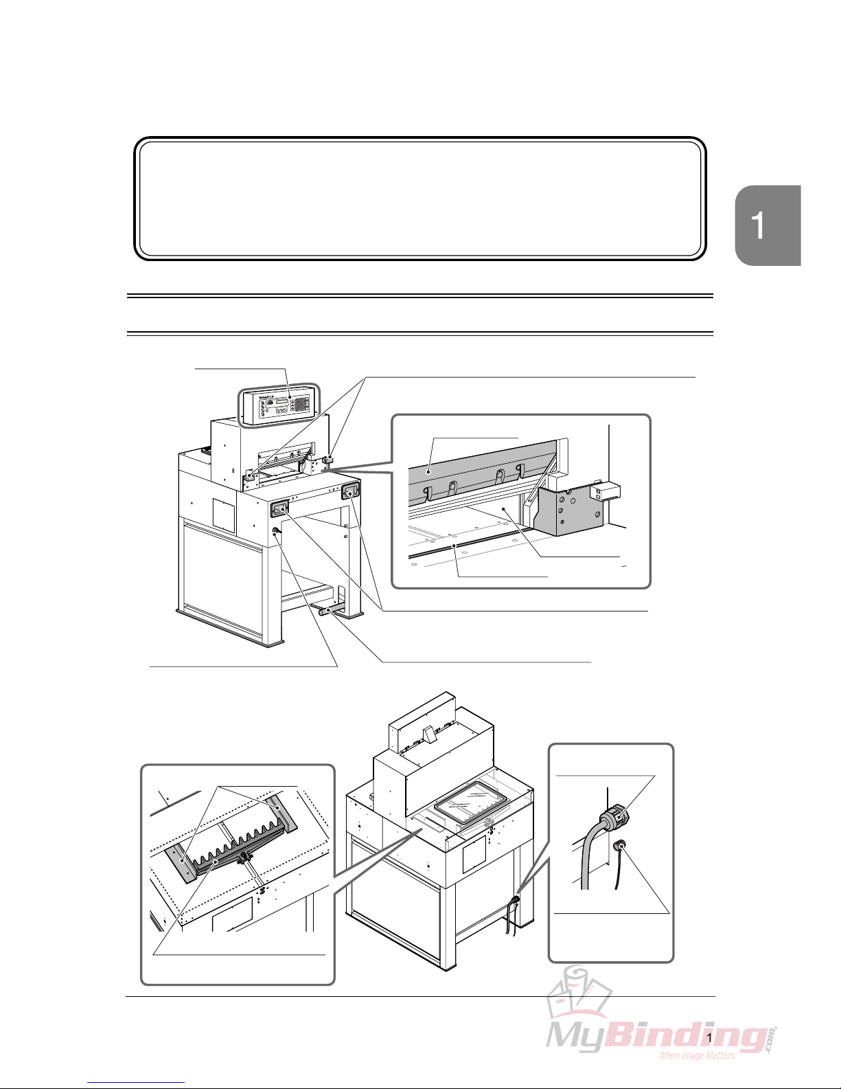
1-1 Machine Descriptions
1. Machine Descriptions
This chapter explains the positions and functions of each part
of this machine in this manual.
Control Panel
See next page.
Beam Light Sensors
Cutting motion does not start even if pressing both cutting buttons
when the invisible light between the beam light sensors is blocked.
Knife Cover
Side Guide
Cutting Stick
Cutting Buttons (Upper Inside)
These buttons must be pressed simultaneously to cut
sheets.
Foot Pedal
Step on this pedal to lower the clamp.
Power Switch
When turning on the power switch, turn
the key clockwise.
When this machine is not in use,
remove the key. An authorized person
should keep the key so that other people can not run the machine.
Side Guides
Backgauge
This backgauge is the back stop
of sheets to be cut.
Power Cable
Ground Terminal
Make sure to connect
the ground wire here.
2
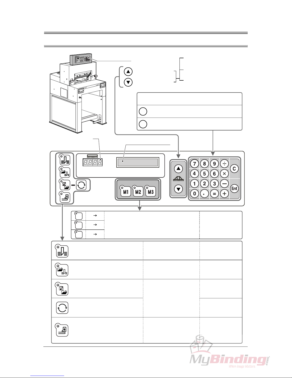
1-2 Control Panel Descriptions
C
Ent
=
=
=
=
=
M1
M2
M3
Control Panel
Backgauge Backward
Backgauge Forward
When pressing once, moves
by 0.1 mm (0.005”)
When continuing to press,
moves at a low speed.
When continuing to press more
than three seconds, moves at a
high speed.
Numeric Keypad:
The input value appears in the guide window.
Clear = The input value is cleared.
Enter = The input value is entered.
Current Position of
the Backgauge
Guide Window
Three programs can be stored. Call your local
dealer if you want to change the program.
See page 20.
Cut sheets according to the current
position of the backgauge without
using program and function key.
For short-run job and same
job pattern.
See page 14.
Cut sheets according to the
programmed value.
For cutting many sheets which
require a complicated process.
See page 17.
Create a new cutting program or
change the saved cutting program.
Create a new cutting program to
repeat the same cutting length.
Only the clamp lifts and lowers.
The knife does not move.
If a program for the cutting job
is created and memorized, it is
useful when performing the
same process repeatedly.
See page 23.
See page 29.
Spine of the saddle-stitched
booklets can be pressed to
reduce the bulk.
See page 22.
3
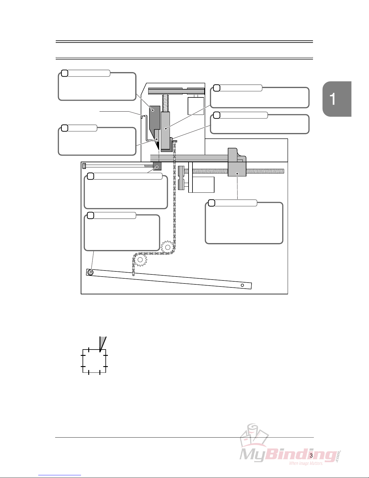
Cutting Mechanism
Machine
Descriptions
1-3 Cutting Mechanism
1
2
4
5
7
6
M
M
3
1
2
3
7
6
8
45
Knife Holder
Knife
After the clamp presses the
sheets, this knife holder lowers
and the sheets are cut.
This knife cuts the sheets. If the
knife edge becomes dull, replace
with a new one.
Knife Cover
Clamp
When the cutting buttons are pressed, this
clamp presses the sheets first.
Foot Pedal Clamp
When the foot pedal (No.7) is stepped,
only this part lowers.
Cutting Stick
The knife cuts into this stick and the
sheets are cut. If the groove of the
cutting stick becomes deep, turn it
by 90 degrees.
Backgauge
This backgauge moves to the
set position. The length
between this backgauge and
the knife will be the cutting
length. This value is indicated
as current position.
Foot Pedal
When this foot pedal is stepped
on, the clamp lowers depending
on the stepping depth.
Use this to check the cutting
position.
• The lowering limit position of the knife (No.2) can be adjusted.
Adjust if the knife height becomes smaller because of resharpening. See page 33.
• The cutting stick (No.4) is cut by the knife and ditched.
When the knife cuts the same position of the cutting stick and the
groove of the cutting stick becomes deep, the bottom sheet may
remain uncut.
In this case, turn the cutting stick and use another face.
The cutting stick provides two surfaces per face.
Therefore, up to eight times - four faces can be used totally.

4
This page is intentionally left blank.
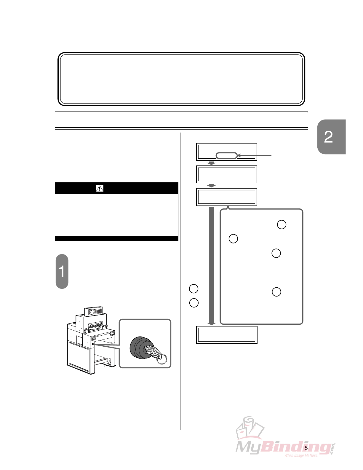
5
Check the Power Switch Safety Checks
2-1 Check the Power Switch
This machine has been designed to be as
safe as possible. However, if an accident
occurs, it can cause severe personal
injury. Before using the machine, always
perform the safety checks listed in this
chapter.
Turn on the power switch.
- When the power switch is turned on, the
screen shown to the upper right appears.
(1) Initial Screen:
When the power switch is turned on.
(2) Initializing Backgauge:
The backgauge moves to the home position
(400 mm [17.00”]).
(3) Knife Replacement Message:
(Only when the knife cuts sheets over 2,000 times.)
(4) Initializing Backgauge Completed:
The backgauge reaches the home position.
2. Safety Checks
This chapter explains how to check the safety functions before
starting the cutting operation.
WARNING
If you notice a problem while making the
safety checks, do not try to correct the
problem by yourself. If the machine is not
working correctly, it may cause severe personal injury. Please notify your local
dealer.
OFF
ON
Power Switch
Horizon APC-45
Horizon APC-45
VX.XX
400.0mm
LOADING
REPLACE KNIFE
PRESS "Ent"
. . .
Guide Window
ROM Version
appears.
(1)
(2)
(3)
(4)
When the
or
key is
pressed,
C
En
t
check that this
screen
appears.
• If the knife replacement is not
necessary, press the or
key.
• When pressing the key,
this message does not appear
until the cutting operation has
been done for another 1,000
times.
When pressing the key,
this message appears when turning on the power switch again.
See “3-8 Knife Replacement
Message” for details.
C
En
t
C
En
t
6
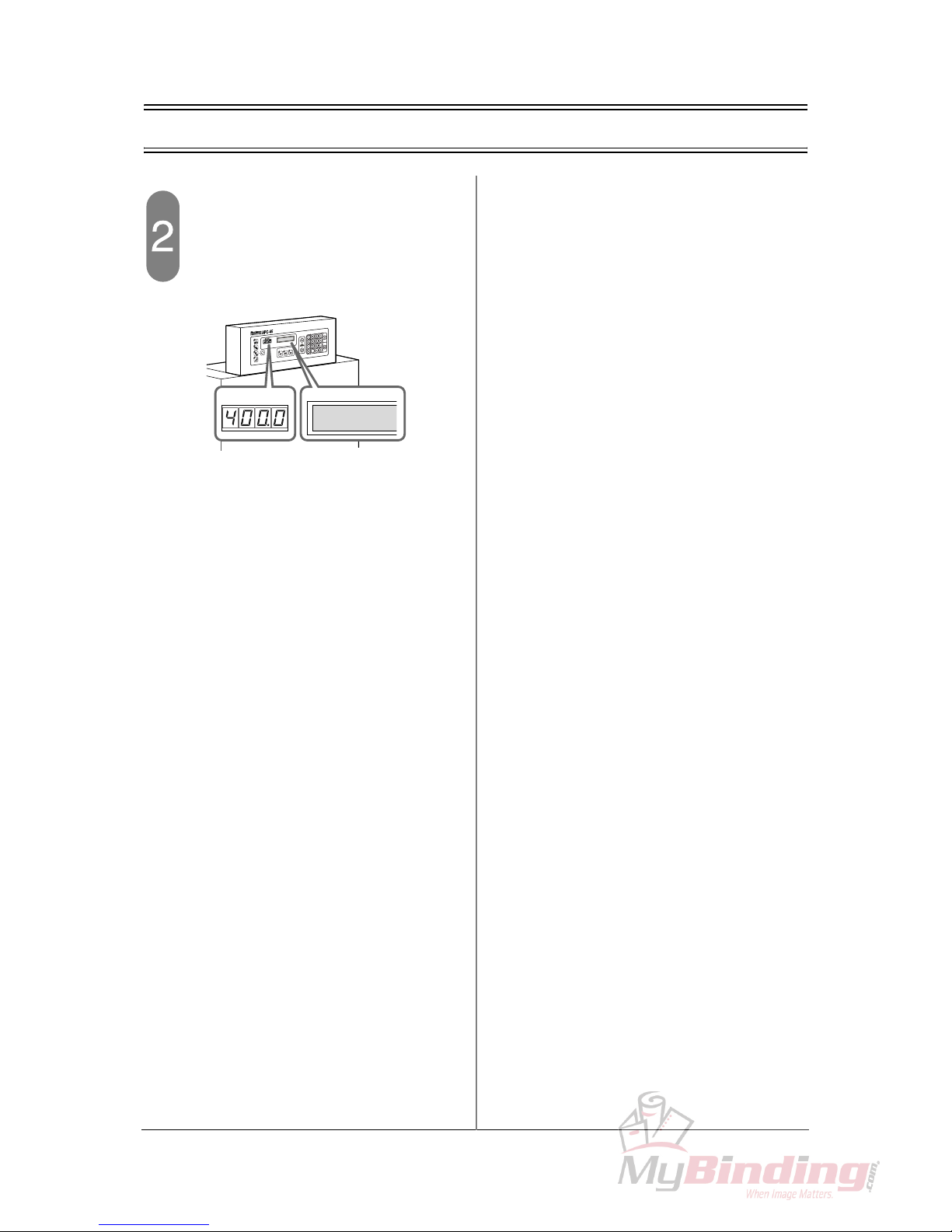
2-1 Check the Power Switch
Check the current position of the
backgauge.
- If the value “400.0” appears in the current
position box and guide window, the power
switch and the software are OK.
400.0mm
7
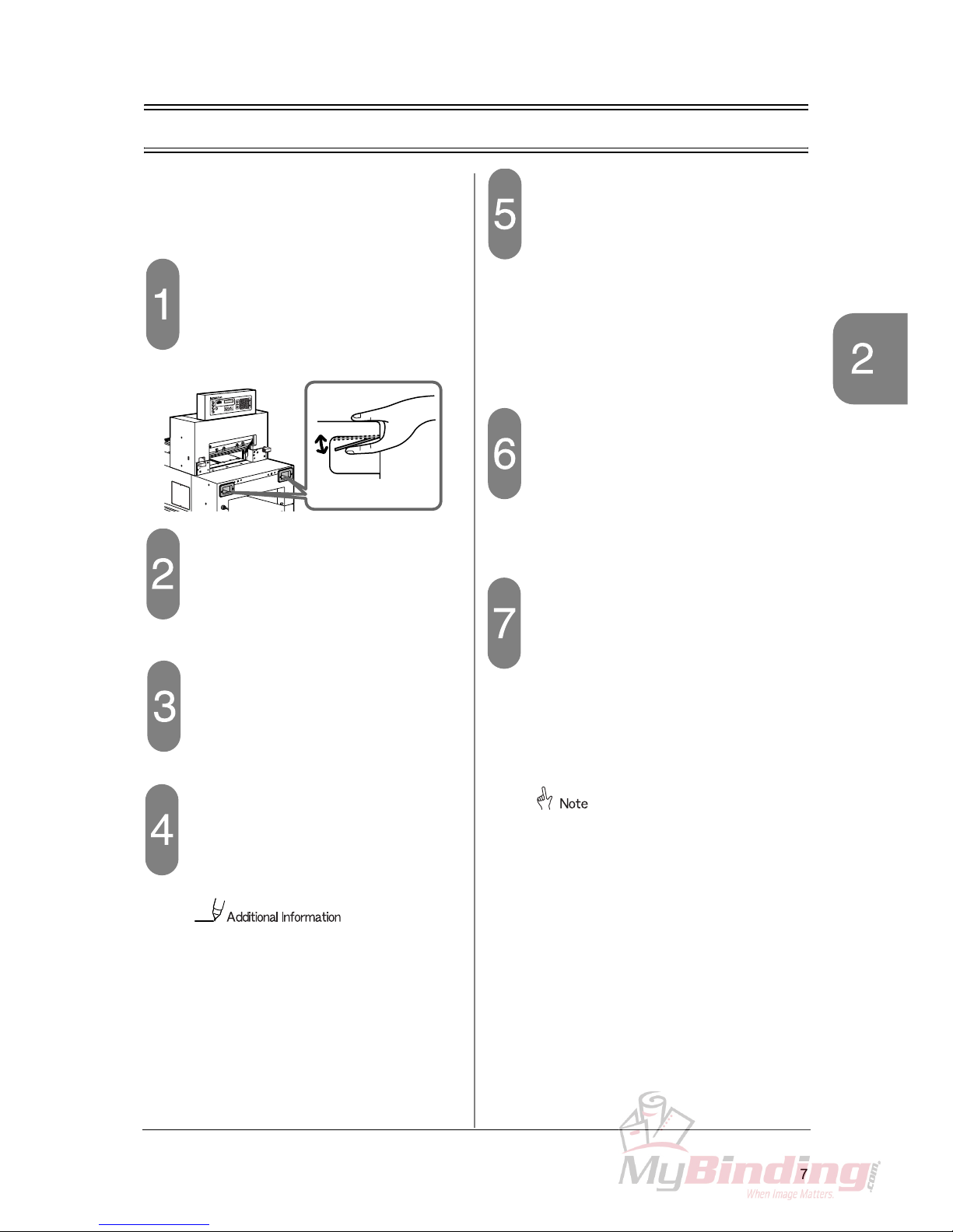
Check the Cutting Buttons Safety Checks
2-2 Check the Cutting Buttons
In the following steps, if the machine does not
operate as explained “the machine is OK”,
stop the check immediately.
Turn on the power switch.
- When the initialization is completed, the current position value (=400.0) appears.
Press only left cutting button continuously.
- If the clamp and the knife do not move, the
machine is OK.
Press only right cutting button continuously.
- If the clamp and the knife do not move, the
machine is OK.
Press left cutting button first and
then press right cutting button more
than 0.5 seconds later.
- If the clamp and the knife do not move, the
machine is OK.
If the knife is not at the upper limit (=
the knife is in the middle position), the
motor reverses when one of the cutting
buttons are pressed and another one is
pressed more than 0.5 seconds later.
- Also press the cutting buttons in the reverse
order and if the clamp and the knife do not
move, the machine is OK.
Press both cutting buttons continuously.
- The cutting process is as follows:
1. The clamp lowers.
2. The knife lowers.
3. The knife lifts.
4. The clamp lifts.
- If the clamp and the knife move in this order,
the machine is OK.
Keep pressing both cutting buttons
after the cutting process.
- When the cutting process is completed, the
clamp and the knife stop at the upper limit
and do not move. If the machine does not
start the next cutting process, the machine is
OK.
Press both cutting buttons, and
then release one of them when the
cutting process starts.
- If the clamp and the knife stop when releasing
one of your hands, the machine is OK.
- Also check by releasing another hand.
- Press both cutting buttons again. The clamp
and the knife will return to the starting position.
If the knife is at the lower limit, the
machine does not stop even if releasing
one of your hands.
Instead, the knife lifts and then the
clamp lifts.
Cutting Buttons
8
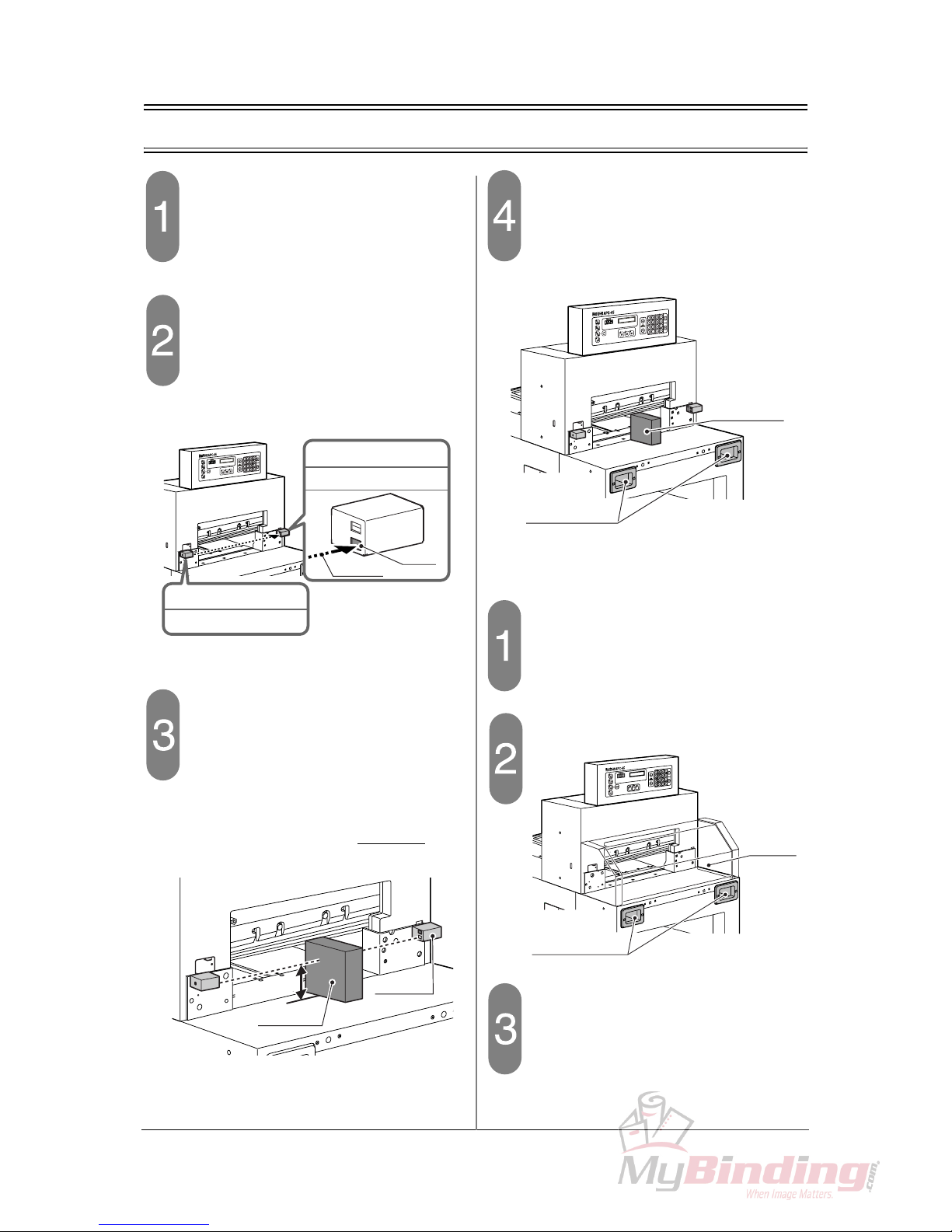
2-3 Check the Beam Light Sensors
Turn on the power switch.
- When the initialization is completed, the current position value (=400.0) appears.
Check the beam sensor.
- If the LED on the receiver on the right sensor
illuminates red, the machine is OK.
Block the beam light between sensors.
- The beam light is about 77 mm (3.0”) above
the table. Place any obstacle on the table to
block the beam. (Do not place the obstacle
under the knife.)
- If the LED on the receiver illuminate, the machine is OK.
Press both cutting buttons.
- Continue to press the cutting buttons while the
obstacle is on the table.
- If the clamp and the knife do not move, the
machine is OK.
If the optional cutting section cover is
installed,
Turn on the power switch.
- When the initialization is completed, the current position value (=400.0) appears.
Open the cutting section cover.
Press both cutting buttons.
- Continue to press the cutting buttons while the
cutting section cover is open.
- If the clamp and the knife do not move, the
machine is OK.
LED
Receiver
Beam
When the beam light
is received
= Red
Beam Light Sensor
Emitter
Beam Light Sensor
“does not”
77mm (3.0")
Receiver
Obstacle
Cutting Buttons
Obstacle
M1
M2
M3
Cutting Buttons
Cutting
Section
Cover
9
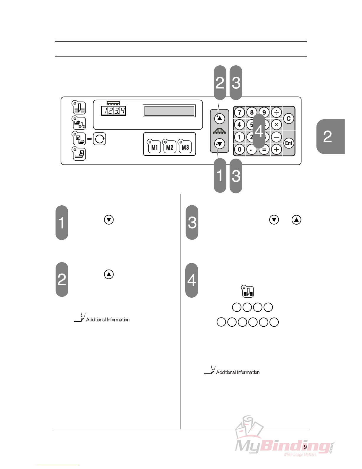
Check the Control Panel Safety Checks
2-4 Check the Control Panel
Press the button.
- Press the button once and release.
- If the value of the current position of the backgauge decreases by 0.1 mm (0.005”), the
software is OK.
Press the button.
- If the value increases more than 0.1, then
decreases gradually and finally the value
increases by 0.1, the software is OK.
Because the screw has a little play,
when the backgauge is moved backward, it is moved backward beyond the
input depth first, and then forward.
Continue to press the or
button.
- If the backgauge moves at low speed in the
arrow direction for three seconds, then it
moves at high speed, the software is OK.
Input 200 (mm) / 7.000 (inch).
- Check that the button is selected and
input the
keys (mm) /
the
keys (inch),
using the numeric keypad.
- If the backgauge moves and the value “200.0 /
7.00” appears in the box of the current position of the backgauge, the software is OK.
When inputting the value 200, the input
of figures after the decimal point is not
necessary.
In the following steps, if the machine does
not operate as explained “the software is
OK”, stop the check immediately.
2 0 0
En
t
. 0 0
7
0
En
t
 Loading...