

MyBinding Plockmatic BM 200 Service Manual

Provided By
http://www.MyBinding.com
http://www.MyBindingBlog.com
Plockmatic BM 200
Booklet Maker
Service Manual

BOOKLET MAKER BM 200
SERVICE MANUAL
12 February 2007
Subject to change

Page intentionally blank

III
IMPORTANT SAFETY NOTICES
1. Before disassembling or assembling parts of the Booklet maker and peripherals.
make sure that the Booklet maker power cord is unplugged,
2. The wall outlet should be near the Booklet maker and easily accessible.
3. Note that some components of the Booklet maker and peripherals are supplied
with electrical voltage even if the main power switch is turned off.
4. If
any adjustment or operation check has to be made with exterior covers off or
open while the main switch is turned on, keep hands away from electrical or
mechanically driven components.
OBSER
VANCE OF ELECTRICAL SAFETY STANDARDS
1. The Booklet maker
and its peripherals must be installed and maintained by a
cust
omer service representative who has completed the training course on those
models.
Always connect the equipment to a properly grounded power source. In doubt, have
the power source checked by a qualied
electrician.
WARNING: Improper connection of the
equipment grounding conductor can result
in electrical shock.
Always follow
all warnings marked on, or
supplied with, the equipment.
Always locate the equipment on a solid
support surface with adequate strength for
the weight of the machine.
Always exercise care in moving or relocating the equipment.
Always keep magnets and all devices with
strong magnetic eld away from the machine.
Never use a ground adapter plug to connect the equipment to a power source that
lacks a ground connection terminal.
Never attempt any maintenance function
that is not specifically described in this
documentation.
Never remove the covers or guards that
are fastened with screws, unless you are a
trained Service representative.
Never install the unit near a radiator or any
other heat source.
Never override or “cheat” electrical or mechanical interlock devices.
Never operate the equipment if you notice
unusual noises or odors. Disconnect the
power cord from the power source and call
your customer service engineer to correct
the problem.
PREVENTION OF PHYSICAL INJURY
SAFETY AND ECOLOGICAL NOTES FOR DISPOSAL
1. Dispose of replaced parts in accordance with local regulations.

Page intentionally blank

V
TABLE OF CONTENTS
1 INSTALLATION PROCEDURE
1.1 INSTALLATION REQUIREMENTS ..........................................................1-1
1.1.1 MINIMUM SPACE REQUIREMENTS .............................................1-1
1.1.2 POWER REQUIREMENTS .............................................................1-2
1.2 INSTALLATION FLOW CHART ...............................................................1-3
1.3 BOOKLET MAKER INSTALLATION ........................................................1-5
1.3.1 ACCESSORY CHECK ....................................................................1-5
1.3.2 INSTALLATION PROCEDURE .......................................................1-6
1.3.3 ADJUSTMENTS ..............................................................................1-7
1.3.4 CONNECTORS .............................................................................1-10
1.4 TRIMMER INSTALLATION .................................................................... 1-11
1.4.1 ACCESSORY CHECK .................................................................. 1-11
1.4.2 INSTALLATION PROCEDURE .....................................................1-12
1.4.3 ADJUSTMENTS ............................................................................1-14
1.4.4 DOCKING .......................................................................................1-17
1.4.5 CONNECTORS .............................................................................1-20
1.5 SQUAREFOLDER INSTALLATION .......................................................1-23
1.5.1 ACCESSORY CHECK ..................................................................1-23
1.5.2 INSTALLATION PROCEDURE .....................................................1-24
1.5.3 ADJUSTMENTS ............................................................................1-27
1.5.4 DOCKING .......................................................................................1-30
1.5.5 CONNECTORS .............................................................................1-32
1.5.6 AUTO SET THICKNESS BRACKET .............................................1-33
2. PREVENTIVE MAINTENANCE SCHEDULE
2.1 PM TABLE ...............................................................................................2-1
3. REPLACEMENT AND ADJUSTMENT
3.1 GENERAL CAUTIONS ............................................................................3-1
3.2 SPECIAL TOOLS AND LUBRICANTS ....................................................3-3
3.2.1 SPECIAL TOOLS ............................................................................3-3
3.2.2 REQUIRED TOOLS ........................................................................3-5
3.2.3 SYMBOLS USED IN TEXT .............................................................3-5
3.3 COVERS ..................................................................................................3-7
3.3.1 FRONT AND REAR COVER ...........................................................3-7
3.3.2 INFEED COVER .............................................................................3-8
3.3.3 INFEEDER ......................................................................................3-9
3.3.4 OUTFEED COVER .......................................................................3-10
3.3.5 UPPER TOP COVER .................................................................... 3-11
3.3.6 REAR TOP COVER ......................................................................3-12
3.3.7 TOP COVER ASSEMBLY .............................................................3-13
3.3.8 INTERLOCK SWITCH S16 &S17 .................................................3-15
3.4 AREA A ..................................................................................................3-17
3.4.1 INFEED MODULE .........................................................................3-17
3.4.2 PAPER INFEED SENSOR ............................................................3-18
3.4.3 INFEED TRANSPORT MODULE ..................................................3-19
3.4.4 INFEED TRANSPORT WHEEL ....................................................3-20

VI
3.4.5 INFEED MOTOR M1 & SENSOR Q2 ...........................................3-21
3.4.6 SIDE GUIDES ...............................................................................3-22
3.4.7 SIDE JOGGER MOTOR M3 & SENSOR Q12 ..............................3-23
3.4.8 SIDE GUIDE TRANSMISSION &SENSOR Q13 ...........................3-24
3.4.9 BACK JOGGER MODULE & SENSOR Q3 ..................................3-26
3.4.10 BACK JOGGER FINGERS ...........................................................3-28
3.4.11 BACK JOGGER MOTOR M2 ........................................................3-30
3.4.12 STAPLER HEAD ...........................................................................3-31
3.4.13 STAPLER HEAD RETRACTION DISTANCE ................................3-34
3.4.14 STAPLER MOTOR M4 ..................................................................3-35
3.4.15 STAPLER ASSY DRIVE BAR & SENSOR Q14 ............................3-36
3.4.16 CLINCHER BAR ASSEMBLY ........................................................3-37
3.4.17 CLEANING CLINCHER POINTS ..................................................3-38
3.4.18 SET TRANSPORT DRIVE ALIGNMENT .......................................3-39
3.4.19 PRESSURE ROLLER ...................................................................3-41
3.4.20 SET TRANSPORT MOTOR M5 ....................................................3-42
3.4.21 THICK SET SENSOR Q36 ............................................................3-43
3.5 AREA B ..................................................................................................3-45
3.5.1 STAPLE STOP GATE SOLENOID SOL1 ......................................3-45
3.5.2 STAPLE STOP GATE RELEASE SOLENOID SOL2 ....................3-46
3.5.3 SADDLE STAPLING START SENSOR Q4 ...................................3-48
3.6 AREA C ..................................................................................................3-49
3.6.1 STAPLE / FOLD POSITION MOTOR M9 & SENSOR Q10 ..........3-49
3.6.2 LENGTH TRANSMISSION SHAFT & SENSOR Q11 ...................3-50
3.6.3 FOLD STOP GATE MOTOR M8 & SENSOR Q7 ..........................3-52
3.6.4 FOLD STOP GATE .......................................................................3-53
3.6.5 FOLD KNIFE MOTOR M7 & SENSOR Q15 .................................3-54
3.6.6 FOLD TRANSMISSION MODULE ................................................3-56
3.6.7 FOLD TRANSMISSION BELT & SENSOR Q9 .............................3-57
3.6.8 FOLD ROLLER MOTOR M6 .........................................................3-59
3.6.9 FOLD TRANSMISSION GEAR ASSEMBLYS ...............................3-61
3.6.10 FOLD DISTANCE BRACKET ........................................................3-62
3.6.11 UPPER FOLDER ROLLER ...........................................................3-63
3.6.12 LOWER FOLDER ROLLER ..........................................................3-65
3.6.13 OUTFEED SENSOR .....................................................................3-67
3.7 PCB .......................................................................................................3-69
3.7.1 MD3DC PCB “H” ...........................................................................3-69
3.7.2 UPPER MD6DC PCB ”B” ..............................................................3-70
3.7.3 LOWER MD6DC PCB ”C” .............................................................3-71
3.7.4 INTERLOCK PCB ”D” ...................................................................3-72
3.7.5 CPU PCB AND COLLATOR INTERFACE PCB ”A” ......................3-73
3.7.6 ADDON PCB ”F” ...........................................................................3-75
3.7.7 LCD PANEL ...................................................................................3-76
3.8 STACKER ..............................................................................................3-77
3.8.1 STACKER MODULE .....................................................................3-77
3.8.2 STACKER MOTOR M1 .................................................................3-78
3.9 BOOKLET QUALITY ADJUSTMENT .....................................................3-79
3.9.1 STAPLE STOP GATE PARALLELISM ..........................................3-79

VII
3.9.2 SIDE GUIDE PARALLELISM ........................................................3-81
3.9.3 STAPLE POSITION TO CLINCHER .............................................3-82
3.9.4 STAPLER PRESSURE .................................................................3-85
3.9.5 CLINCHER POINTS HEIGHT .......................................................3-86
3.9.6 CLINCHER PRESSURE ...............................................................3-87
3.9.7 STAPLE AND FOLD POSITION ....................................................3-89
3.9.8 FOLD SKEW .................................................................................3-91
3.9.9 STAPLE POSITION ON SQUARE FORMED SPINE ....................3-92
3.10 POWER REQUIREMENTS ...................................................................3-93
3.10.1 TAPPING THE TRANSFORMER ..................................................3-93
4. TROUBLESHOOTING
4.1 FAULT CODE DESCRIPITIONS..............................................................4-1
4.2 BLOWN FUSE CONDITIONS ...............................................................4-31
4.3 LEDS .....................................................................................................4-33
4.4 TEST POINTS .......................................................................................4-39
5. SERVICE TABLES
5.1 SERVICE PROGRAM MODE ..................................................................5-1
5.1.1 SERVICE PROGRAM MODE OPERATIONS .................................5-1
5.1.2 SERVICE PROGRAM MODE TABLES ...........................................5-4
Check Motors and function .........................................................................5-4
5.1.3 EEPROM RESET ..........................................................................5-12
5.2 SOFTWARE DOWNLOAD ....................................................................5-13
5.2.1 Downloading to upper PCB MD6DC B in Booklet maker. .............5-13
5.2.2 Downloading to lower PCB MD6DC C in the Booklet maker. .......5-14
5.2.3 Downloading to PCB CPU in Booklet maker. ................................5-15
5.2.4 Downloading to lower PCB MD3DC H in the Booklet maker. .......5-16
5.2.5 Downloading to PCB MD6DC A in Trimmer. .................................5-17
5.2.6 Downloading to PCB MD6DC D in Squarefolder. .........................5-18
5.3 SELF-DIAGNOSTIC MODE ..................................................................5-19
5.3.1 RUN TIME DIAGNOSTICS ...........................................................5-19
5.3.2 POWER ON SELF TEST ..............................................................5-19
5.3.3 DETAILED SELF-DIAGNOSTIC MODE ........................................5-20
5.4 PAPER SIZE RESET ....................................................................5-21
5.5 SQF SERVICE .......................................................................................5-25
6. DETAILED SECTION DESCRIPTIONS
6.1 ELECTRICAL COMPONENT LIST ..........................................................6-1
6.1.1 FRONT VIEW ..................................................................................6-3
6.1.2 REAR VIEW ....................................................................................6-4
6.1.3 CONNECTOR VIEW .......................................................................6-5
6.1.4 OUTFEED UPPER VIEW ...............................................................6-6
6.1.5 OUTFEED LOWER VIEW ...............................................................6-7
6.1.6 INFEED UPPER VIEW ...................................................................6-8
6.1.7 INFEED LOWER VIEW ...................................................................6-9
6.1.8 INFEED MODULE VIEW ..............................................................6-10
6.1.9 STACKER MODULE VIEW ........................................................... 6-11
6.2 BOARD STRUCTURE ...........................................................................6-13
6.2.1 BLOCK DIAGRAM ........................................................................6-13
6.2.2 CONTROLLER CPU .....................................................................6-14

VIII
6.2.3 CONTROLLER MD6DC ................................................................6-15
6.2.4 CONTROLLER MD3DC ................................................................6-17
6.2.4 CONTROLLER MD3DC, CONTINUES .........................................6-18
6.3 BOOKLET
MAKING PROCESS ............................................................6-19
6.3.1
PRINCIPLE OF OPERATION .......................................................6-19
6.3.2 SIZE ADJUSTMENT .....................................................................6-23
SPECIFICATIONS
BOOKLET MAKER BM 200 ..................................................................Spec-1
TRIMMER FTR 200 ..............................................................................Spec-1
SQUAREFOLDER SQF 200 .................................................................Spec-1
WIRING
Booklet Maker ...............................................................................................Wir-1
Trimmer .........................................................................................................Wir-1
Squarefolder .................................................................................................Wir-1

IX
1 INSTALLATION PROCEDURE
1.1 INSTALLATION PROCEDURE ........................................................FTR-1-1
2 PREVENTIVE MAINTENANCE SCHEDULE
2.1 PREVENTIVE MAINTENANCE SCHEDULE ..................................FTR-2-1
3. REPLACEMENT AND ADJUSTMENT
3.1 COVERS ..........................................................................................FTR-3-1
3.1.1 FRONT AND REAR COVER ...................................................FTR-3-1
3.1.2 TOP COVER
...........................................................................FTR-3-2
3.1.3 BLOWER MOTOR M5 / M6 ....................................................
FTR-3-3
3.1.4 INFEED COVER .....................................................................FTR-3-4
3.1.5 LOCKING BRACKET ..............................................................FTR-3-5
3.1.6 UPPER OUTFEED COVER
....................................................FTR-3-6
3.1.7
INTERLOCK SWITCH S9 &S10 .............................................FTR-3-7
3.1.8
LOWER OUTFEED COVER ...................................................FTR-3-8
3.1.9 PROTECTION COVER ...........................................................FTR-3-9
3.2
AREA C ..........................................................................................FTR-3-11
3.2.1 INFEED SENSOR Q13 .........................................................FTR-3-11
3.2.2 CONTROL SWITCH S2 ........................................................
FTR-3-12
3.2.3 CONTROL SWITCH S3 ........................................................FTR-3-13
3.2.4 TRANSPORT MOT
OR M1 ....................................................FTR-3-14
3.2.5 TRANSPORT BELT SENSOR Q4 .........................................FTR-3-15
3.2.6 TRIM KNIFE MOTOR M2 ......................................................FTR-3-16
3.2.7 TRIM KNIFE HOME POSTITON SENSOR Q5 .....................
FTR-3-17
3.2.8 TRIM KNIFE ..........................................................................FTR-3-18
3.2.9 PAPER PA
TH & OUTFEED SENSOR Q6 .............................FTR-3-22
3.2.10 STOP GATE CARRIAGE ......................................................FTR-3-23
3.2.11 STOP GATE MOTOR M3 & SENSOR Q7 .............................FTR-3-24
3.2.12 LENGTH ADJUSTMENT MOT
OR M4 & SENSOR Q12 .......FTR-3-25
3.2.13 LENGTH ADJUSTMENT HOME POSITION SWITCH S11 ..FTR-3-26
3.2.14 LOWER OUTFEED BELTS ...................................................
FTR-3-27
3.2.15 UPPER OUTFEED BELTS ....................................................FTR-3-28
3.2.16 TRIM BIN FULL SENSOR Q8 ...............................................FTR-3-29
3.2.17 TRANSMISSION CHAIN .......................................................FTR-3-30
3.2.18
KNIFE SUPPORT CHAIN .....................................................FTR-3-31
3.2.19 KNIFE CHAIN .......................................................................FTR-3-32
3.2.20
INFEED BELTS .....................................................................FTR-3-33
3.3 PCB ...............................................................................................FTR-3-35
3.3.1 MD6DC PCB ”A” ...................................................................FTR-3-35
4. TROUBLESHOOTING
4.1 FAULT CODE DESCRIPTIONS.......................................................FTR-4-1
5 SERVICE TABLES
5.1 SERVICE TABLES ...........................................................................FTR-5-1
PERIPHERALS
TRIMMER FTR 200

X
6. DETAILED SECTION DESCRIPTIONS
6.1 ELECTRICAL COMPONENT LIST ..................................................FTR-6-1
6.1.1 REAR VIEW ............................................................................FTR-6-2
6.1.2 INFEED VIEW .........................................................................FTR-6-3
6.1.3 OUTFEED VIEW .....................................................................FTR-6-4
6.1.4 STOP CARRIAGE VIEW .........................................................FTR-6-5
6.2 BOARD STRUCTURE .....................................................................FTR-6-7
6.2.1 BLOCK DIAGRAM ..................................................................FTR-6-7
6.2.2 CONTROLLER MD6DC ..........................................................FTR-6-8
6.2.2 CONTROLLER MD6DC, CONTINUES ...................................FTR-6-9
6.3 TRIMMING PROCESS ..................................................................FTR-6-11
6.3.1 PRINCIPLE OF OPERATION ...............................................FTR-6-11
6.3.2 SIZE ADJUSTMENT .............................................................FTR-6-13
6.3.2 SIZE ADJUSTMENT .............................................................FTR-6-14
SPECIFICATIONS
SPECIFICATIONS ...............................................................................FTR-Spc-1
WIRING
Trimmer .................................................................................................FTR-Wir-1

XI
1 INSTALLATION PROCEDURE
1.1 INSTALLATION PROCEDURE ........................................................SQF-1-1
2 PREVENTIVE MAINTENANCE SCHEDULE
2.1 PREVENTIVE MAINTENANCE SCHEDULE ..................................SQF-2-1
3 REPLACEMENT AND ADJUSTMENT
3.1 COVERS ..........................................................................................SQF-3-1
3.1.1 FRONT COVER ......................................................................SQF-3-1
3.1.2 REAR COVER ........................................................................SQF-3-2
3.1.3
INFEED COVER .....................................................................SQF-3-3
3.1.4
OUTFEED COVER .................................................................SQF-3-4
3.1.5 TOP COVER
...........................................................................SQF-3-6
3.1.6 TILT
THE MACHINE ...............................................................SQF-3-7
3.2 MOTORS .........................................................................................
SQF-3-9
3.2.1 TRANSPORT BELT MOTOR (M1) ..........................................SQF-3-9
3.2.2 STOP GA
TE MOTOR (M2) ...................................................SQF-3-10
3.2.3 CLAMP MOTOR (M3) ...........................................................SQF-3-11
3.2.4 ROLLER MOTOR (M4) AND PRESSURE ROLLER .............SQF-3-12
3.3 SENSORS AND SWITCHES .........................................................
SQF-3-15
3.3.1 STOP GATE SENSOR (Q1) ..................................................SQF-3-15
3.3.2 ROLLER MOTOR FRONT/REAR SENSORS (Q2 AND Q3)
SQF-3-16
3.3.3 CLAMP MOTOR HOME POSITON SENSOR (Q4) ..............SQF-3-17
3.3.4 INFEED / OUTFEED SENSORS (Q5 AND Q7) ....................SQF-3-18
3.3.5 CLAMP SENSOR (Q6) ..........................................................
SQF-3-20
3.3.6 MOTOR M4 ENCODER SENSOR (Q8) ................................SQF-3-21
3.3.7 TOP COVER INTERLOCK SWITCHES (S
2 & S4) ...............SQF-3-22
3.3.8 UPPER TRANSPORT BELT CLUTCHES (SOL1 & SOL3) ...SQF-3-23
3.3.9 LOWER TRANSPORT BELT CLUTCHES (SOL2 & SOL4) ..SQF-3-24
3.4 BELTS ............................................................................................
SQF-3-25
3.4.1 UPPER TRANSPORT BELT .................................................SQF-3-25
3.4.2 LOWER TRANSPORT
BELT ................................................SQF-3-26
3.4.3 TEFLON TAPE LOWER TRANSPORT BELT ....................SQF-3-29
3.5 MECHANICS .................................................................................SQF-3-31
3.5.1 SET CLAMPS ........................................................................
SQF-3-31
3.5.2 STOP GATE ..........................................................................SQF-3-34
3.6 PCB ...............................................................................................SQF-3-37
3.6.1
PCB MD6DC “D” ...................................................................SQF-3-37
3.7 POWER REQUIREMENTS
...........................................................SQF-3-39
3.7.1
TAPPING THE
TRANSFORMER ..........................................SQF-3-39
4. TROUBLESHOOTING
4.1 FAULT CODE DESCRIPTIONS.......................................................SQF-4-1
4.2 BLOWN FUSE CONDITION ..........................................................SQF-4-13
4.3 LED’S .............................................................................................SQF-4-15
4.4
TEST POINTS ...............................................................................SQF-4-17
PERIPHERALS
Squarefolder SQF 200

XII
5 SERVICE TABLES
5.1 SERVICE TABLES ...........................................................................SQF-5-1
6. DETAILED SECTION DESCRIPTION
6.1 ELECTRICAL COMPONENT LIST ..................................................SQF-6-1
6.1.1 COMPONENT LAYOUT ..........................................................SQF-6-2
6.2 BOARD STRUCTURE .....................................................SQF-6-5
6.2.1 CONTROLLER MD6DC “D” ....................................................SQF-6-5
6.3 PRINCIPLE OF OPERATION ..........................................................SQF-6-7
SPECIFICATIONS
SPECIFICATIONS .............................................................................. SQF-Spc-1
WIRING
Squarefolder ........................................................................................SQF-Wir-1
1-1
Installation
31 January 2007
1 INSTALLATION PROCEDURE
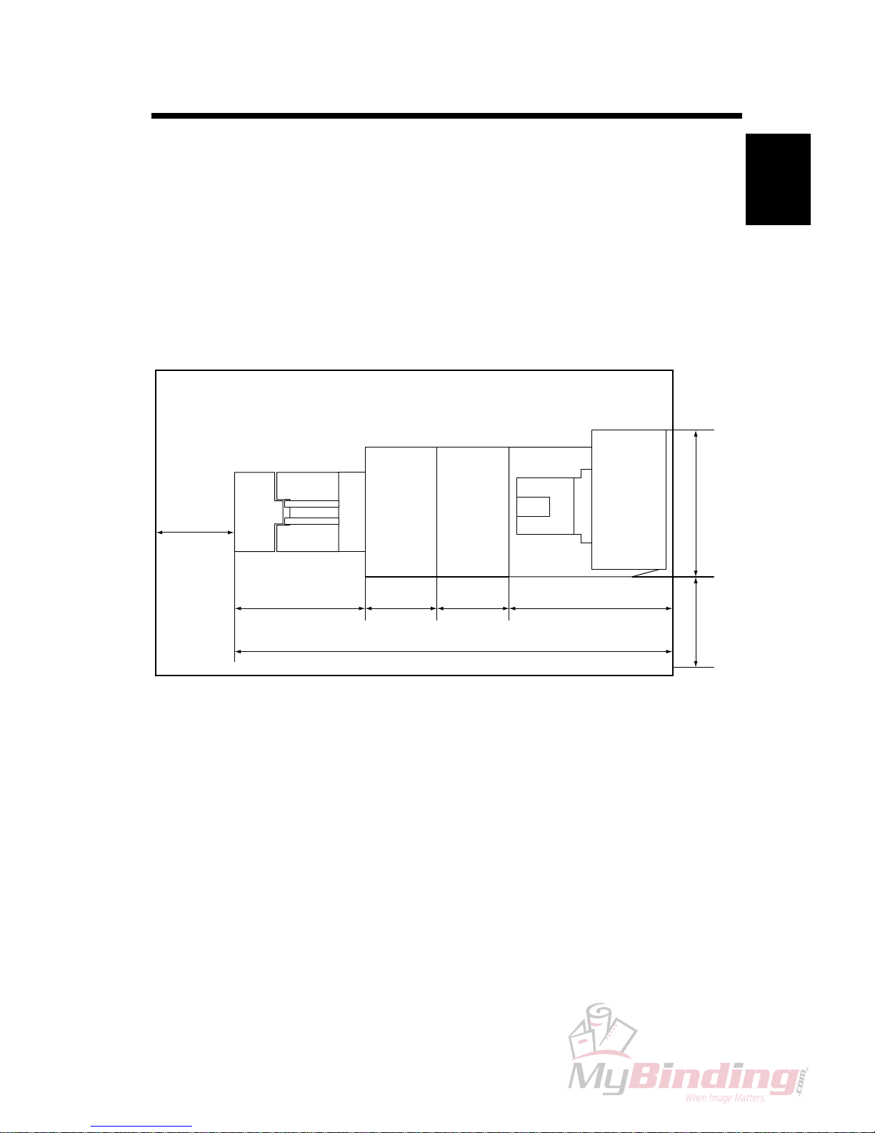
1.1 INSTALLATION REQUIREMENTS
1.1.1 MINIMUM SPACE REQUIREMENTS
INSTALLATION REQUIREMENTS
SQF 200 FTR 200 BM 200
Stacker
810 mm
31.9”
350 mm
13.75”
350 mm
13.75”
625 mm
24.38
”
400 mm
15.75”
2135 mm
84”
670 mm
26.4”
555 mm
21.9”

1-2
31 January 2007
1.1.2 POWER REQUIREMENTS
1. Input voltage level:
North America 120V AC, 50-60Hz: More than 4 A.
Europe/Asia 230V AC, 50-60Hz: More than 2 A.
2. Permissible voltage uctuation: ± 10%
3. Never place anything on the power cord.
INSTALLATION REQUIREMENTS
WARNING
1. Make sure that the wall outlet is near the main machine and easily
accessible.Makesuretheplugisrmlyinsertedintheoutlet.
2. Avoid multi-wiring.
3.
Be sure to ground the machine.
1-3
Installation
31 January 2007 INSTALLATION FLOW CHART
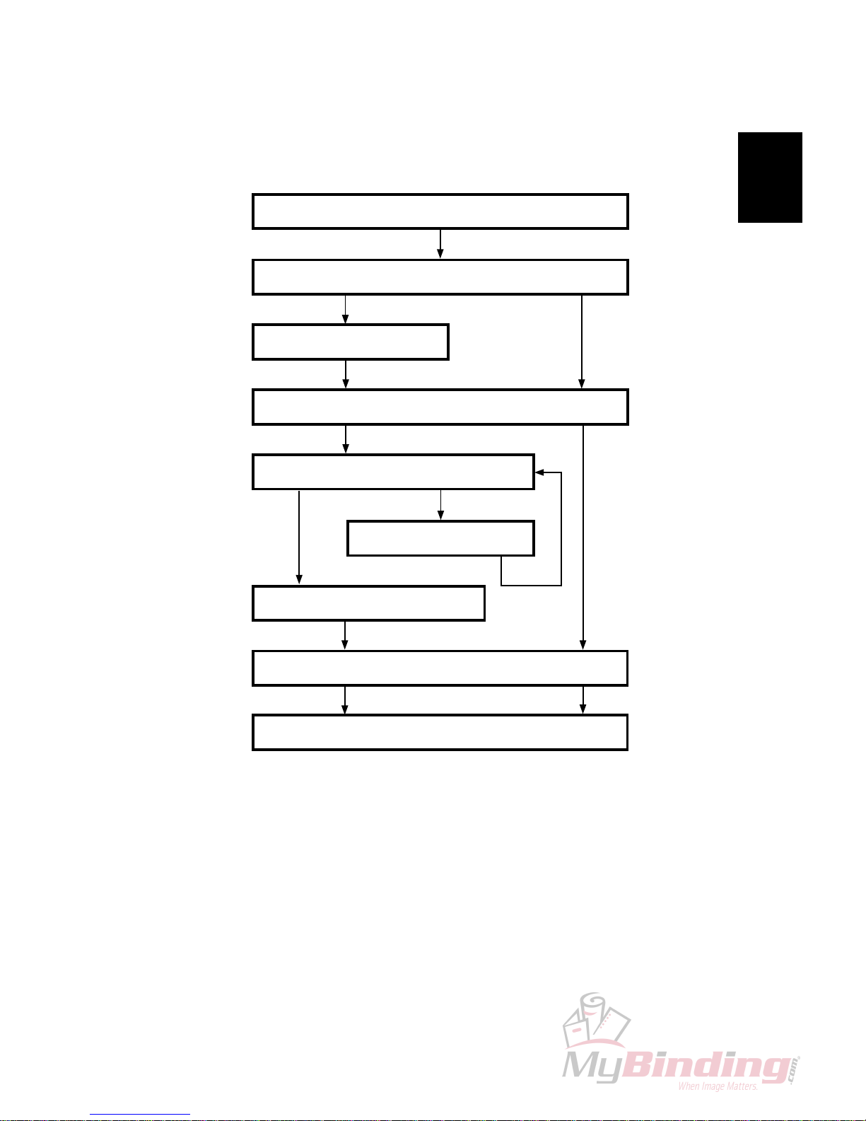
1.2 INSTALLATION FLOW CHART
The following ow chart shows how to install the optional units more efciently.
FTR 200 Trimmer: Enables On-line trimming. Especially thicker sets ( > 4
sheets) look unprofessional because of ”creep”. FTR 200
will trim those edges (up to 15 mm / 19/32”).
SQF 200 SquareFolder: Enables the possibility to give the booklets the perfect
bound look.
Yes
No
Install the Booklet Maker BM 200
Does the user require a Trimmer?
Install the Trimmer FTR 200
Does the user require a SquareFolder?
Is a Trimmer installed?
Yes No
Install the SquareFolder SQF 200
Install the Belt Stacker
Yes
Install Trimmer
No
Check the Installation

Page intentionally blank
1-5
Installation
31 January 2007
1.3 Booklet Maker INSTALLATION
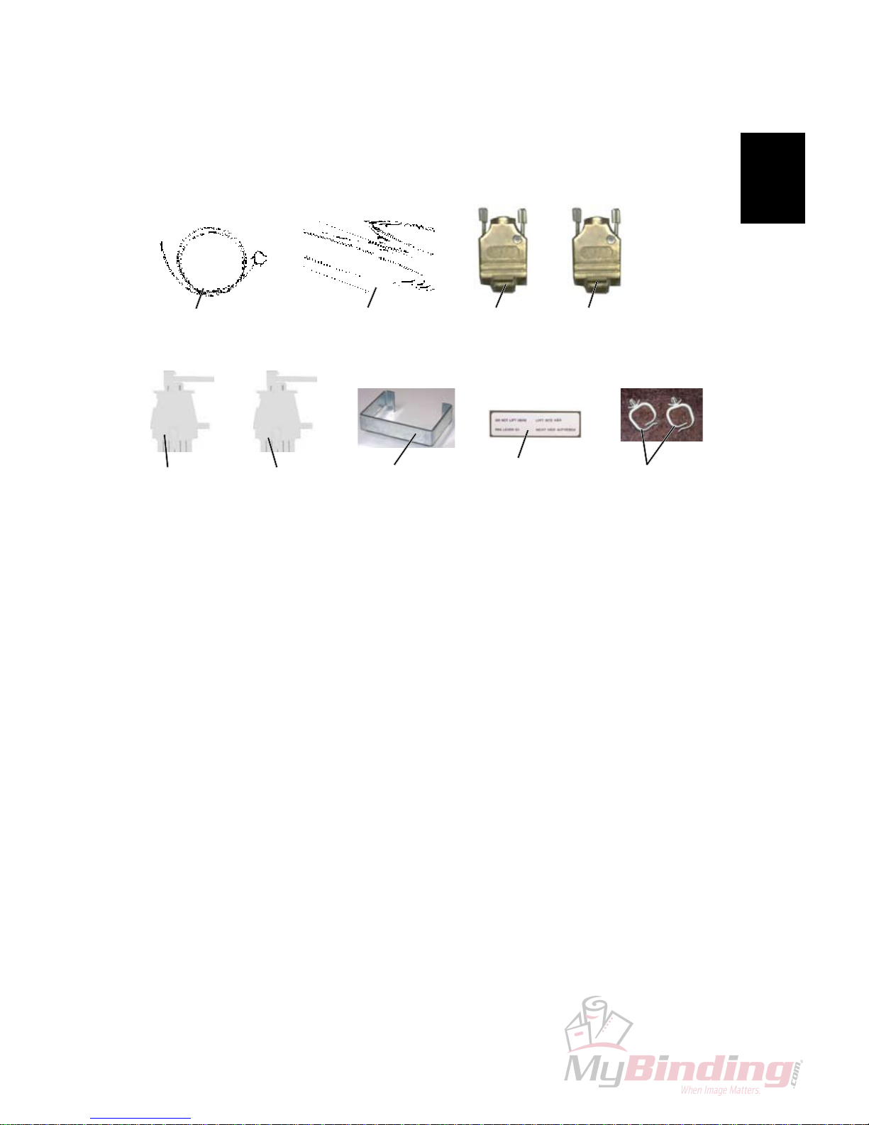
1.3.1 ACCESSORY CHECK
Check the quantity and condition of the accessories in the box against the following list:
Description Q’ty
A. Communication Cable .......................................................... 1
B. Powercord ............................................................................ 1
C. Terminator plug, will always be installed onto BM 200 ......... 1
D Terminator plug FTR 200 ..................................................... 1
E. Interlock Jumper, will always be installed onto BM 200 ...... 1
F. Interlock Jumper FTR 200 .................................................... 1
G. Cable protector ..................................................................... 1
H. Cable protector sticker ........................................................ 1
I. Cable holder ......................................................................... 1
[A]
[B]
[D]
[C]
[E]
[F]
BOOKLET MAKER INSTALLATION
[G]
[H]
[I]
1-6
31 January 2007
BOOKLET MAKER INSTALLATION
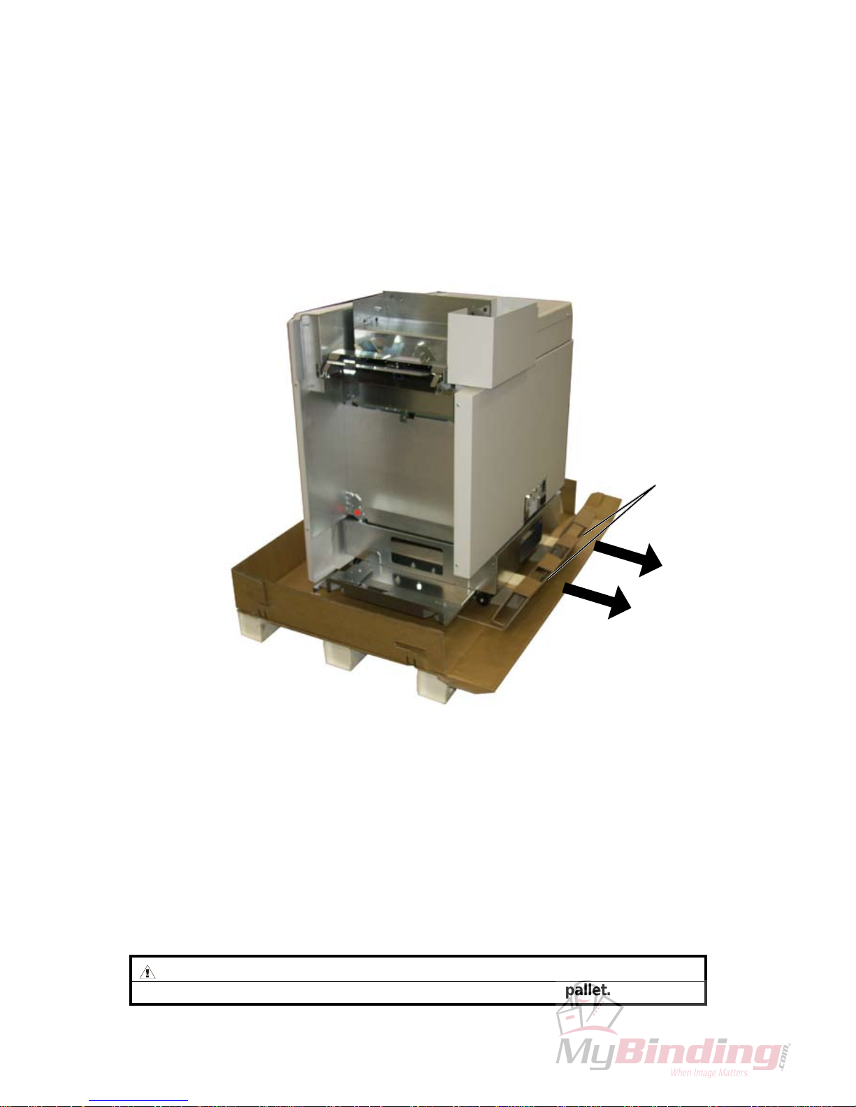
1.3.2 INSTALLATION PROCEDURE
Unpacking
1. Remove all parts from the pallets.
2. Slide the Booklet Maker off the pallet by pulling the two cardboard handles [A]
underneath the Booklet Maker straight out.
WARNING
2 persons are required to slide the Booklet Maker off the pallet.
[A]
1-7
Installation
31 January 2007
BOOKLET MAKER INSTALLATION
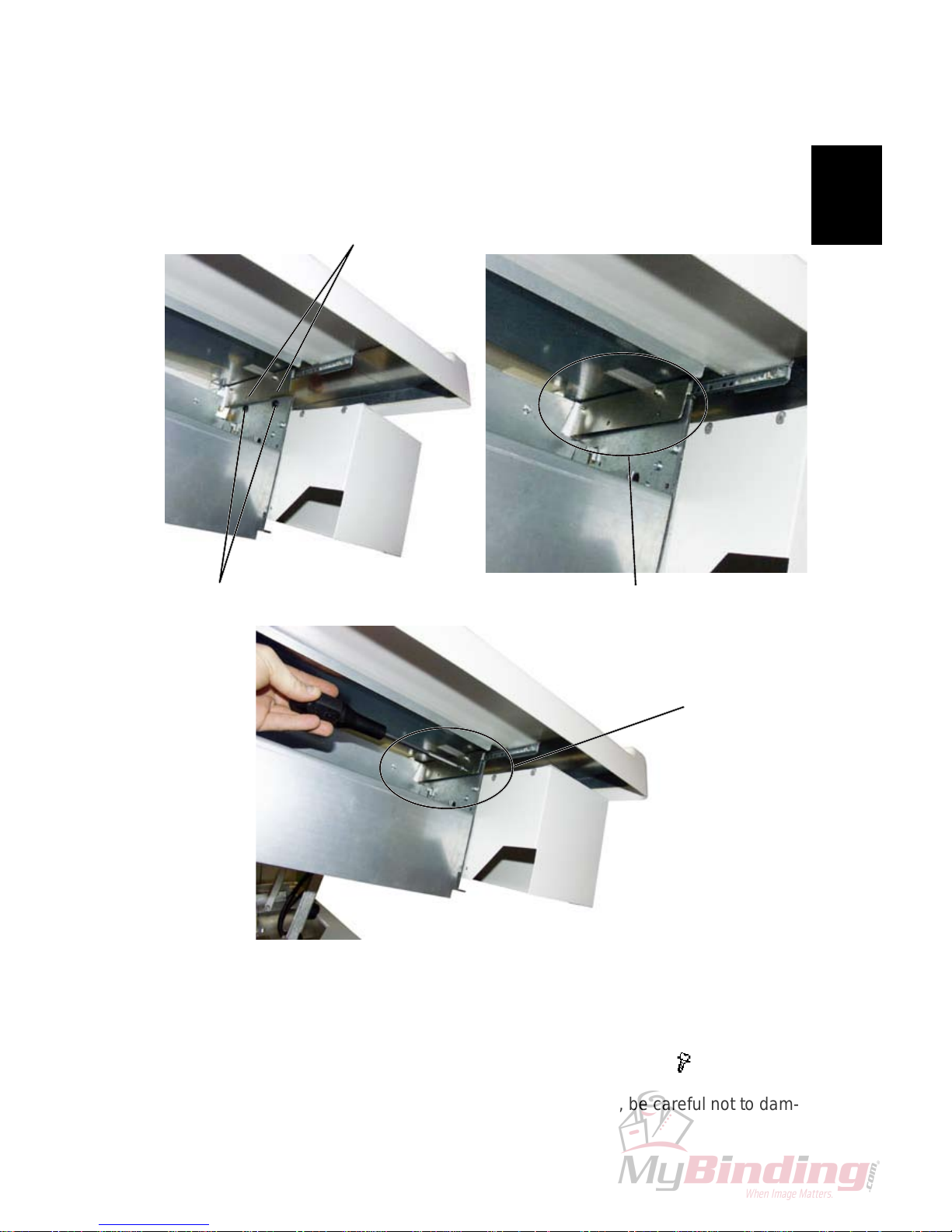
Upper Top Cover
1. Hold the Upper Top Cover in position and lower the rear end so that the grommets [A] and the holes in the guide brackets [B] are centered towards each
other [C].
2. Secure the rear end of the Upper Top Cover with screws [D] (
x2).
NOTE: After securing the rear end of the Upper Top Cover, be careful not to dam-
age the guide by lifting the front end.
[A]
[C]
[D]
[B]
1-8
31 January 2007
BOOKLET MAKER INSTALLATION
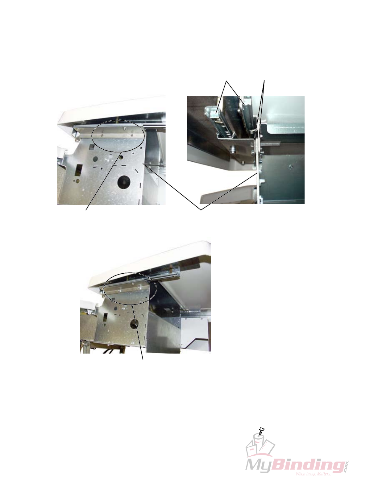
4. Lower the front end of the Upper Top Cover so that the holes in the guide braclets and the holes in the Top Cover frame are centered towards each other [E].
NOTE: There are two guides [F] and two brackets [G] on the front side of the
Upper Top Cover. Make sure that these guides are positioned on each side of
the the Upper Top Cover frame part [H].
5. Secure the front end of the Upper Top Cover with screws [I] (
x2).
[E]
[I]
[H]
[F]
[G]
1-9
Installation
31 January 2007
1.3.3 ADJUSTMENTS
BOOKLET MAKER INSTALLATION
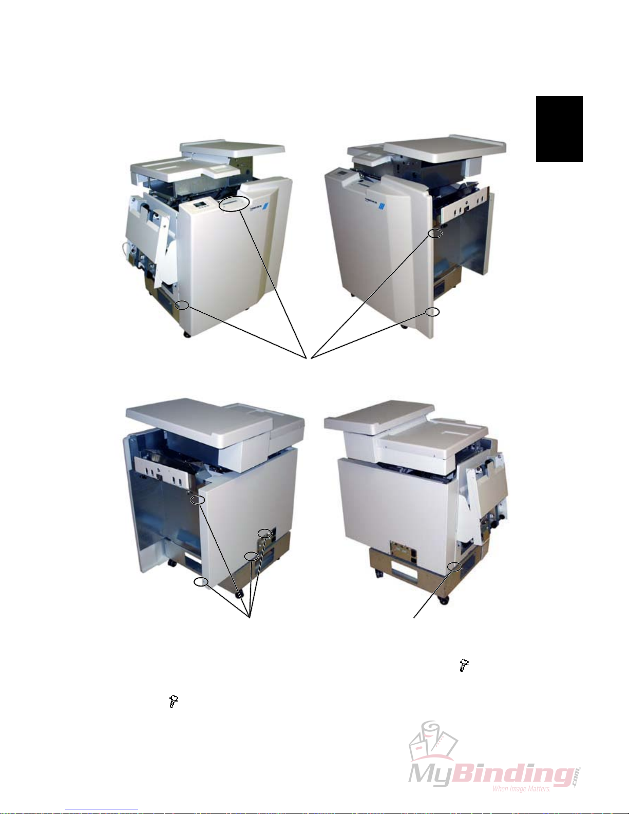
1. Remove screws [A] and remove the Booklet Maker front cover ( x5).
2. Remove screws [B], loosen screw [C] and remove the Bookler maker rear
cover (
x5).
[A]
[B] [C]

1-10
31 January 2007
BOOKLET MAKER INSTALLATION
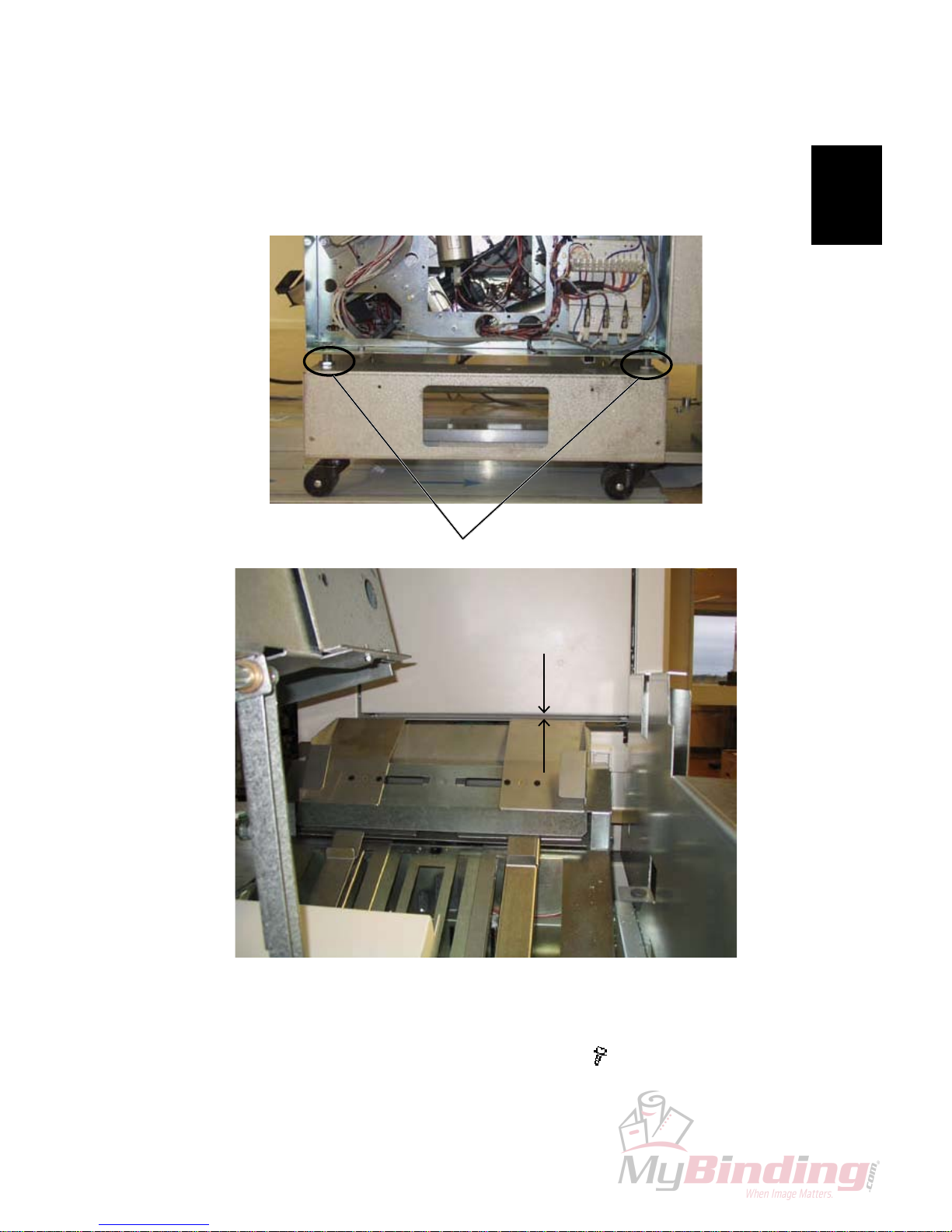
3. Mount the supplied positioning pins on the collator.
4. Dock the collator to the Booklet Maker. See picture above.
1-11
Installation
31 January 2007
BOOKLET MAKER INSTALLATION
5. Turn the four adjustment nuts [A] until the distance [B], between the lower
edge of door and the top of side guide, is 3 mm.
6. Reinstall the Booklet Maker front and rear covers (
x 10).
[A]
Booklet Maker, front view
[B]
1-12
31 January 2007
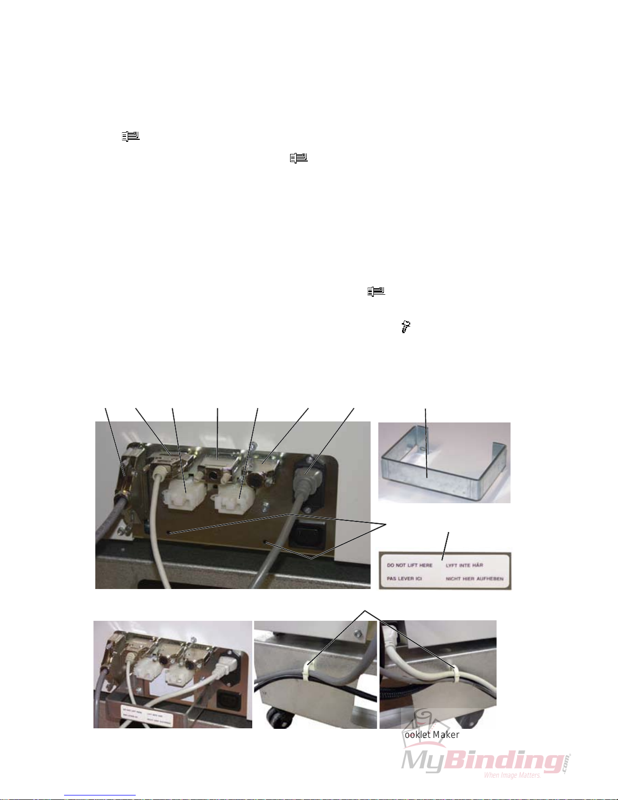
1.3.4 CONNECTORS
1. If a collator is present, connect the communication cable [A] from the collator
( x1), to the Booklet Maker.
2. Connect the Belt Stacker cable [B] (
x1).
NOTE: Unless Trimmer FTR 200 and/or SquareFolder SQF 200 will be installed.
If so, Belt Stacker cable will be connected to the last module in the system.
3. Install the Terminator plug [C] and the Interlock jumper [G].
NOTE: The Terminators and Interlock jumpers are stored in the installation kit.
4. Install the Terminator plug [D] and the Interlock jumper [F].
NOTE:
Unless Trimmer FTR 200 will be installed. If so, communication cable
and power cord between BM 200 and FTR 200 will be connected.
5. Connect the powercord [E] to the Booklet Ma
ker (
x1).
6. Mount the cable protector [H] positioned as shown with two screws in the
holes [I] and route the cables inside the cable protector (
x 2).
7. Attach the sticker “Do not lift here” [J] on the cable protector.
8. Install the cable holders [K] on the rear side of the Booklet Maker base and
route the cables through them.
BOOKLET MAKER INSTALLATION
[H]
[J]
[B][A] [C] [D] [E][F][G]
Only Booklet Maker installed
[I]
[K]
Cable protector mounted Cable holder mounted on Booklet Maker
1-13
Installation
31 January 2007
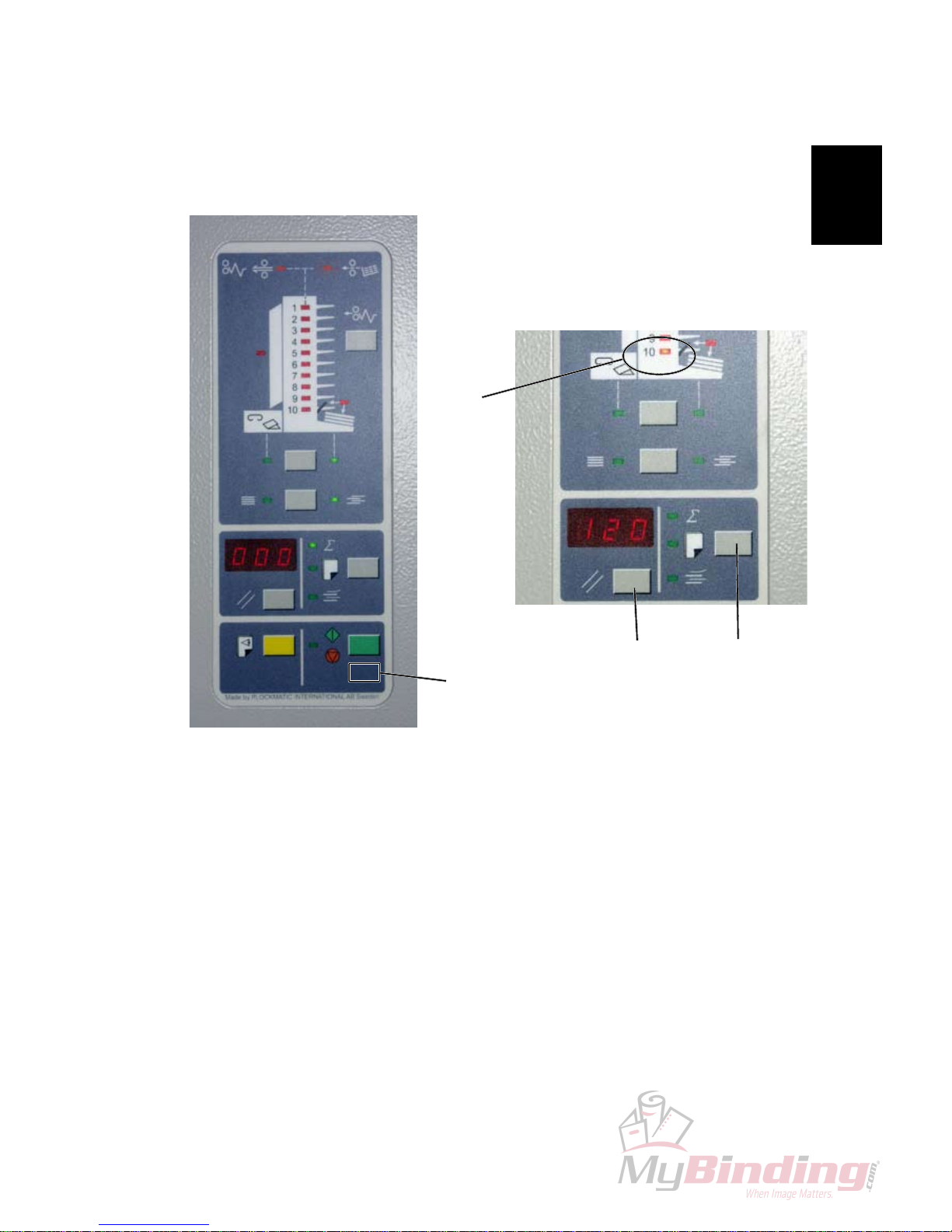
1.3.5 CHANGING SPEED ON THE COLLATOR
BOOKLET MAKER INSTALLATION
1. Enter Collator program mode by pressing hidden button [A] and holding it until
all green LED’s goes out.
2. Press button [B] repeatedly until programmable setting No. 10 is displayed.
This is indicated when bin LED 10 [C] on the Collator display is lit. The correct
value for setting No. 10 should read 120. If so, continue to step 5.
3. Press button [D] once to display the last digit. Press button [B] to change the
last digit.
Press button [D] to also display the middle digit. Press button [B] to change
the middle digit.
Press button [D] to also display the rst digit. Press button [B] to change the
rst digit.
4. Conrm changing setting No. 10 by pressing
button [D]
[A]
[D] [B]
[C]
Continued on next page....
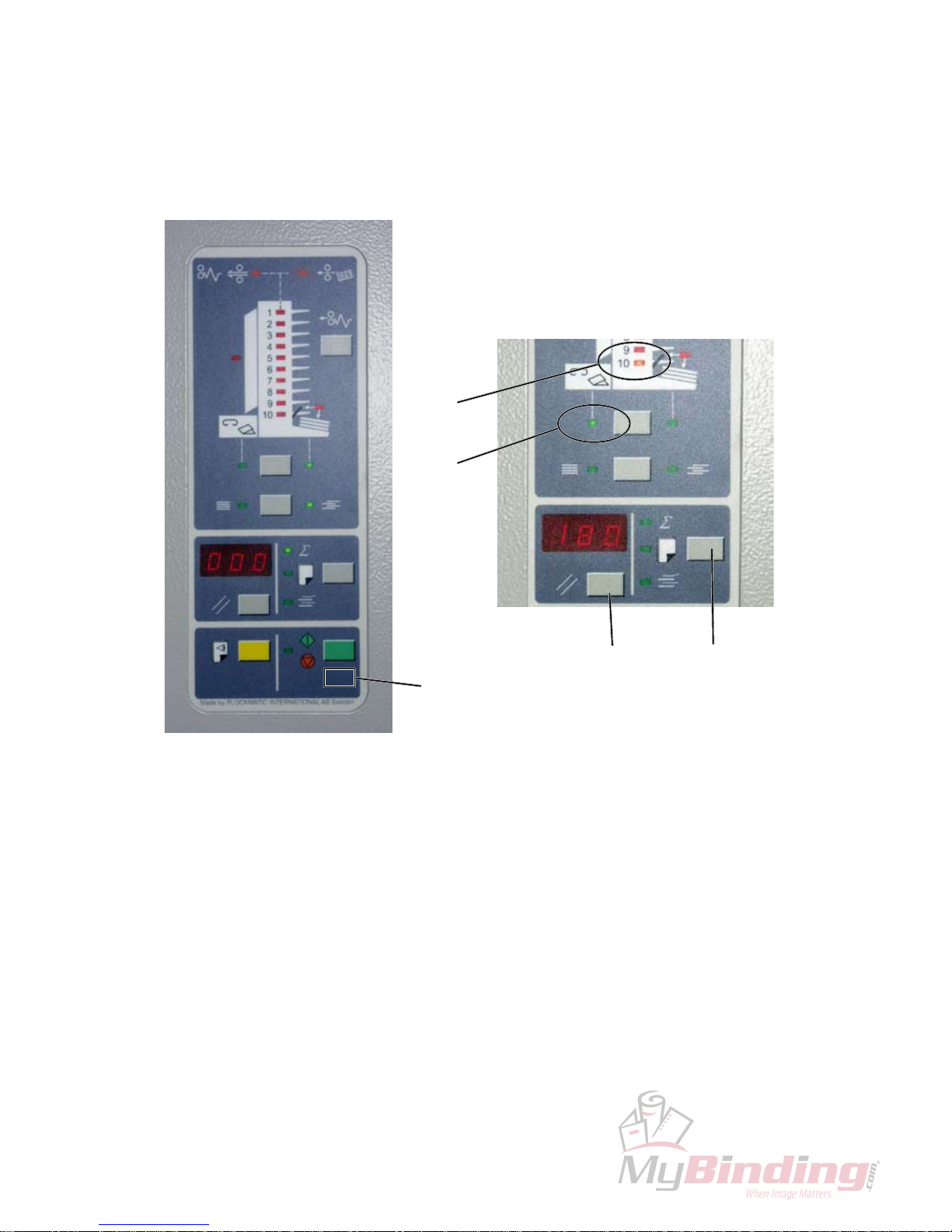
1-14
31 January 2007
5. Press button [B] repeatedly until programmable setting No. 20 is displayed.
This is indicated when bin LED 10 [C] and third party LED [E] on the Collator display are lit. The correct value for setting No. 20 should read 180. If so,
continue to step 8.
6. Press button [D] once to display the last digit. Press button [B] to change the
last digit.
Press button [D] to display the middle digit. Press button [B] to change the
middle digit.
Press button [D] to display the rst digit. Press button [B] to change the rst
digit.
7. Conrm changing setting No. 20 by pressing button [D].
8. Press hidden button [A] to exit Collator programming mode.
BOOKLET MAKER INSTALLATION
[A]
[D] [B]
[C]
[E]

1-15
Installation
31 January 2007
1.3.6 CHECK THE INSTALLATION
1. If installing a Trimmer FTR 200, continue to section ( 1.4 ) otherwise
continue with step 2.
2. Power on the Booklet maker and the Collator.
3. Remove the two Stapler heads, according to section (
3.4.12 ).
4. Perform a Detailed self-diagnostic, according to section (
5.3.3 )
5. Reinstall the two Stapler heads, according to section (
3.4.12 ).
6. Set up the Collator to send A4/8.5 x 11” sheets to the Booklet Maker.
7. Set up the Booklet maker to A4/8.5 x 11”.
8. Set up the Booklet maker to Staple ON.
9. Feed a A4/8.5 x 11” set to the Booklet maker.
10. Check for the correct feeding of the set from the Collator.
NOTE: If paper is not fed correctly, check adjustment of the Booklet maker
according to section (
1.3.3 ).
11. Set up the Collator to send A3/11 x 17” sheets to the Booklet Maker.
12. Set up the Booklet maker to A3/11 x 17”.
13. Set up the Booklet maker to Staple ON.
14. Feed a A3/11 x 17” set to the Booklet maker.
15. Check for the correct feeding of the set from the Collator.
NOTE: If paper is not fed correctly, check adjustment of the Booklet maker
according to section (
1.3.3 ).
BOOKLET MAKER INSTALLATION

Page intentionally blank

1-17
Installation
31 January 2007
1.4 TRIMMER INSTALLATION
1.4.1 ACCESSORY CHECK
[A]
Check the quantity and condition of the accessories in the box against the following list:
NOTE: - The Installation Box is located in the trim bin on the Trimmer.
- The trim bin is tie wrapped on the rear side.
- T
rimmer fan is bubble wrapped and located inside the Trimmer.
- The Rail Extension is located in the packing material
Description Q’ty
A. Communication cable between the Booklet Maker .............. 1
and the Trimmer
B. Powercord between the Booklet Maker and T
rimmer .......... 1
C. Trimmer fan assy ................................................................. 1
D. Cable protector ..................................................................... 1
E. Cable protector sticker ......................................................... 1
F. Cable holder ......................................................................... 1
[B]
TRIMMER INSTALLATION
[C]
[D] [E] [F]
 Loading...