


Provided By
http://www.MyBinding.com
http://www.MyBindingBlog.com
Duplo Docu Cutter
DC-545HC
Service Manual

SERVICE MANUAL
Ver.1
DOCU CUTTER
DC-545HC
Be sure to read this manual carefully, so that you
repair and service this machine safely and correctly.
Do not begin work until you have thoroughly
understood the contents of this manual.
Repairing or servicing the machine with insuffeicient
knowledge about it could lead to unforeseen
accidents or falls in the machine's performance or
quality.
DUPLO SEIKO CORP.


Introduction
The cause of most accidents is failure to adhere to basic safety rules and observe safety
instructions. It is important to prevent potential causes of accidents from occurring. In
order to do so, read this manual carefully, and be sure to understand all the safety instructions and correct inspection and servicing procedures that it provides before beginning
repair or servicing work.
Repairing or servicing the machine with insufficient knowledge about it could lead to
unforeseen accidents.
It is not possible to anticipate and describe in a manual such as this every possible
hazard that could arise in the course of repair and servicing. Therefore, besides observing
the safety instructions marked in this manual and on the machine's labels, service
personnel should be safety-conscious and take other safety precautions as necessary. When
performing repair or service work not covered by this manual, you should obtain safety
guidance from an appropriately knowledgeable person.
Copyright © 2003
DUPLO SEIKO CORPORATION
All Rights Reserved
1

Safety instructions
Safety instructions
1.Cautions regarding the installation location
Safety instructions
Installation environment
s Avoid installing the machine in places exposed to direct sunlight.
• Sunlight will cause the temperature in the machine’s interior to rise, possibly leading to malfunction of the control system.
• Sunlight could cause misoperation of the sensors.
• The heat of direct sunlight could cause deformation of the machine’s plastic parts.
* Also avoid installation near to a ground glass window; light and heat penetrate such windows
although they are opaque.
s Avoid installing the machine in places subject to high or low temperature or humidity.
• High or low temperature or humidity could cause the machine to operate abnormally.
Suitable temperature and humidity ranges are:
Ambient temperature: 5˚C–30˚C
Ambient humidity: 40%–70%
Optimum temperature and humidity: 20˚C, 65%
• If the machine is installed near to faucets, water heaters or humidifiers, or in cool (sunless) parts
of a building or in the vicinity of water sources, the paper could absorb moisture and curl,
leading to misfeeds or poor image quality.
s Avoid installing the machine in places with open flames, or where reflected heat or other hot air
currents (from stoves, etc), or cold air currents from coolers, etc will strike it directly.
s Avoid installing the machine in poorly ventilated places.
s Avoid installing the machine in dusty places.
s The machine should not be tilting when it is used.
• Install the machine so that it is level.
(The machine should be level to within 5mm in the front-rear direction, and 5mm in the lateral
direction.)
s Do not install the machine on shaky, sloping or otherwise unstable surfaces.
• The machine could fall over on such surfaces, or fall off them, causing injury.
2
Safety instructions
2. Cautions for installation work
Warning
• The machine’s power supply voltage and power consumption depend on the model. Details of this
are given in the tables below. The power supply voltage and power consumption for the machine
are given in the table below. The machine’s power supply voltage is indicated on the identification
plate located on the machine’s left side; the machine must be connected to a power supply of the
voltage indicated.
a Otherwise, fire or electric shock could result.
If the power supply voltage is unstable or if the power supply has insufficient capacity, the
machine may not operate normally.
Make sure that the power supply has sufficient capacity for the system as a whole, including
optional equipment.
* 120V AC model
Power supply voltage
With no load*
At full load
Power consumption
No more than 130V AC
At least 110V AC
During operation : 90W
In standby : 15W
Connect to outlet of 120V AC, 60Hz, at least 15A
Use power supply meeting these requirements
}
* 230V AC model
Power supply voltage
With no load*
At full load
Power consumption
* “With no load” - when the machine is on standby.
* “At full load” - when the machine is running at maximum power consumption.
No more than 250V AC
At least 210V AC
During operation : 90W
In standby : 15W
Connect to outlet of 230V AC, 50Hz, at least 8A
Use power supply meeting these requirements
}
• Use only the power cord that is provided among the accessories.
Insert the power cord plug firmly into the socket, so that proper electrical contact is effected.
• Install the machine close to its power supply. The outlet used should be exclusively for the
machine, and have no other equipment connected to it.
If an extension cord is necessary, it should have a ground terminal, and be of the following ratings:
* For a 120V AC model: 130V, at least 15A, length not exceeding 5m.
* For a 230V AC model: 250V, at least 8A, length not exceeding 5m.
• Never tread on the power cord or pinch it between other objects, or accidents could result.
CAUTION
• Install the machine in accordance with the installation procedure appended to this manual.
Using the stand
• Lock the casters after the machine is installed.
a Otherwise, the machine could move or fall over, causing injury.
• To move the machine, push it by its mounting base.
a Pushing the DC-545 could make it fall over.
3
Safety instructions
3. Cautions for maintenance, inspection and servicing
Warning
Precautions for safe servicing
• Always remove the power cord plug from the outlet before starting work.
aOtherwise, you could get a shock or your hands/fingers could be injured.
• However, the plug must be left connected to the outlet when performing function checks (of
individual motors, a given series of operations, or electrical circuits). When motors are operated
alone in function checks, interlocks are deactivated, so be aware of the conditions and positions of
related equipment, and take great care not to put your hands or fingers into moving parts.
• The cutter unit and slitter unit contain hazardous sharp blades. Exercise great care when inspecting
the cutter unit or replacing it or its parts.
aOtherwise, your hands/fingers could be injured.
• Do not touch the drum or rollers after turning on the jog switch.
• Do not put your hands or fingers inside the machine while the drum is rotating.
aOtherwise, your hands/fingers could get caught and crushed between the drum and rollers.
Working clothes
• Wear clothing than enables you to work safely.
CAUTION
Tools
• Use tools that are appropriate for the work.
4
Safety instructions
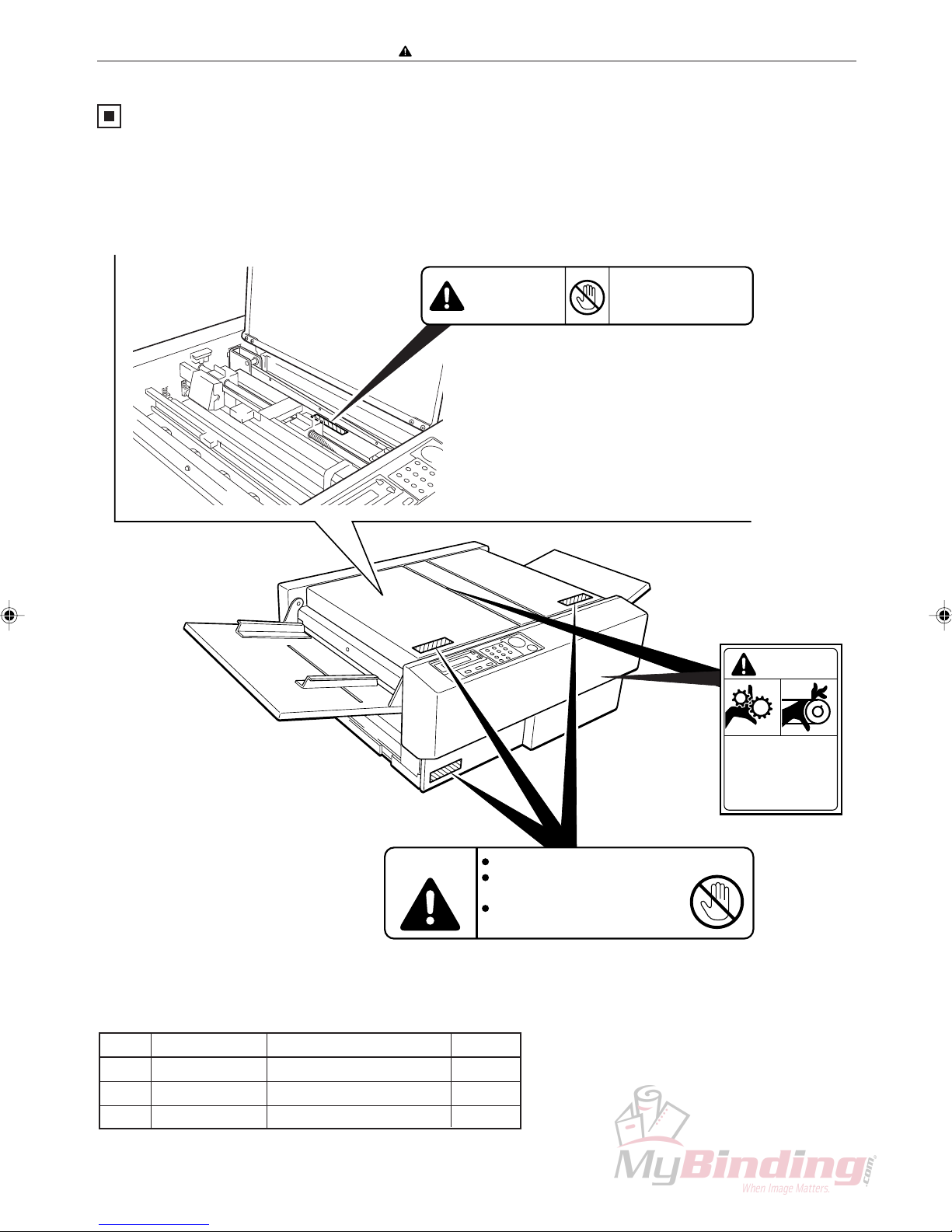
Warning Sticker
Keep the WARNING stickers clean at all times. If labels become damaged or come off, have your service
representative replace them.
q
Do not touch blade!
WARNING
To remove jammed paper,
use the tweezers.
L8-T1100
w
WARNING
No. Parts No. Name Q’ty
q L8-T1100 Warning Sticker 1 1
w L8-T1080 Warning Sticker 2 3
e L8-T1090 Label Caution 2
e
Use caution when working
near movable parts.
Disconnect power before
servicing.
Cutters and movable parts are inside this cover.
Before opening the cover to work,
unplug the power cord.
Use caution when working near cutters
and movable parts.
L8-T1080
WARNING
L8 T1090
5

Safety instructions
6

Introduction
Description of Operation
Mechanical
Standard Adjustments
Chapter 1
Chapter 2
Chapter 3
Chapter 4
Maintenance Checks
Troubleshooting
HELP Mode
Miscallaneous
Chapter 5
Chapter 6
Chapter 7
Chapter 8
7

Table of Contents
Introduction ....................................................... 1
Safety instructions............................................ 2
1. Cautions regarding the installation
location .......................................................... 2
2. Cautions for installation work ...................... 3
3. Cautions for maintenance, inspection and
servicing ........................................................ 4
Warning Sticker................................................. 5
Chapter 1 Introduction
z Specifications ............................................. 10
x Dimensions ................................................. 11
c Part Names and Functions ........................ 12
v Work Flow .................................................... 15
b Options ........................................................ 16
Chapter 2 Description of Operation
z Paper Feed Unit .......................................... 18
x CCD Mechanism ......................................... 30
c Margin Slitter............................................... 32
v Guillotine Cutter Unit ................................. 34
b Creaser Unit ................................................ 35
n Center Slitter ............................................... 37
m Paper Eject Tray .......................................... 39
, Main Drive ................................................... 40
. Skew Adjustment Mechanism ................... 43
⁄0 BAR CODE .................................................. 44
⁄1 REGISTER MARK ....................................... 45
Chapter 4 Standard Adjustments
z LCD Panel.................................................... 94
x Slitter Position ............................................ 95
c Cutter Registration ..................................... 98
v Creaser Calibration .................................. 100
b CCD Horizontal Line Alignment .............. 102
n Adjusting Crease Depth........................... 104
m Feed Solenoid Adjustment ...................... 105
, Gate Solenoid Adjustment (Without the
DC-545HC)................................................. 106
. Cutter Assembly Perpendicularity
Adjustment................................................ 107
⁄0 Creaser Perpendicularity Adjustment .... 108
⁄1 CCD Vertical Line Alignment ................... 109
⁄2 Elevator Switch Height Adjustment........ 111
⁄3 Cover Switch (AF-100 : 1 position,
DC-545 : 2 positions)................................ 112
⁄4 Shutter Solenoid....................................... 113
⁄5 Creaser Sensor Plate Adjustment........... 118
Chapter 5 Maintenance Checks
z Cleaning and Oiling.................................. 120
x Periodic Maintenance Check List............ 120
Chapter 6 Troubleshooting
z T roubleshooting Guide............................. 124
x Error Display ............................................. 132
Chapter 3 Mechanical
z Exterior ........................................................ 49
x Feed Section ............................................... 52
c CCD Section................................................ 59
v Margin Slitter Section................................. 60
b Cutter Section ............................................. 67
n Creaser Section .......................................... 69
m Center Slitter Section ................................. 71
, Driving Section ........................................... 79
. Electric Section........................................... 85
Chapter 7 Help Mode
z HELP Mode List ........................................ 140
x Functions and operation procedures for
each HELP mode ...................................... 141
c HELP Description ..................................... 142
v Select Language for Displays ................. 150
Chapter 8 Miscallaneous
z Job List...................................................... 152
x
Position and Function of Electronic Parts ..
c Overall Wiring Diagram ............................ 161
8
156

Chapter 1 Introduction
z Specifications ............................................ 10
x Dimensions ................................................ 11
c Part Names and Functions ....................... 12
1. Appearance........................................... 12
2. Operation Panel.................................... 14
v Work Flow................................................... 15
1. Operations ............................................ 15
b Options ....................................................... 16
1
9

Chap.1
z Specifications
z Specifications
Product name/Model No. DC-545 with HC AUTO FEEDER
Input paper size Min.: 8.5” x 11”/A4
Max.: 12.6” x 18”/A3
Input paper weight Min.: 110 gsm, Max.: 230 gsm <No curl in the paper>
Finishing size Min.: 2” (Width) x 3.5” (Length) <Business card size>
Lead edge trim Min.: 0.125” (3.2 mm)
Trail edge trim Min.: 0.125” (3.2 mm)
Side edge trim Min.: 0.125” (3.2 mm), Max.: 4.5” (114 mm)
Speed Max.: 9 ppm (A4 lengthwise, 4-side trim, 1 crease)
Trim/Crease tolerance ± 0.03” (± 0.762 mm)
<With paper cutting length not exceeding 18”>
Media type Range: Regular copy paper to coated heavy weight paper
Feeding method Automatic Feeding (Air suction method)
Feed tray capacity 100 mm
Stacker Drop type
Power supply AC 120 V ±10%, 50/60 Hz, 1.0 A
AC 230 V ±10%, 50/60 Hz, 0.6 A
Machine dimensions (mm) 1376 (W) x 576 (D) x 948 (H)
Machine weight (kg) 109.6 (Main body 56.4, Feeder 20.4, Stand 32.8)
1. Four creases perpendicular to the feed direction.
Other Features 2. Up to ten cuts perpendicular to the feed direction.
3. Automatic setting of slit, cut and crease position.
10

x Dimensions
Chap.1
x Dimensions
11
Chap.1
c Part Names and Functions
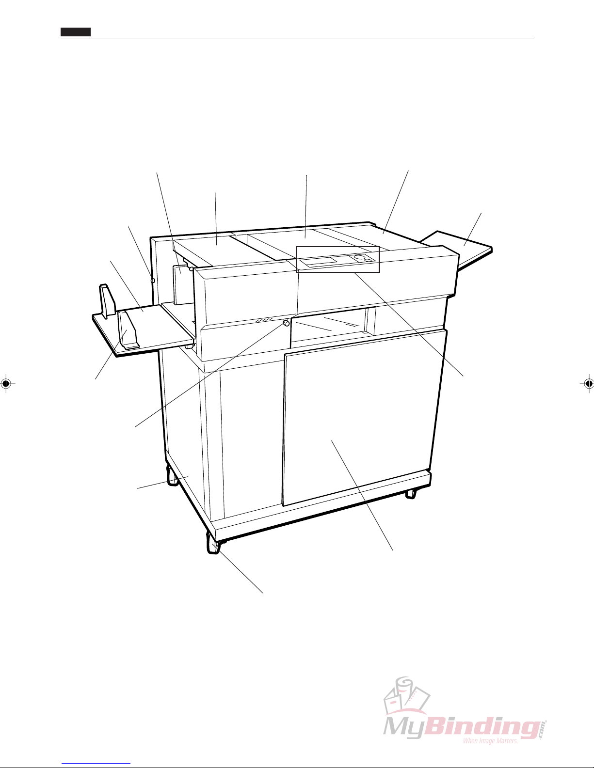
c Part Names and Functions
1. Appearance
Guide Plate
Blower Air ADJ Knob
Feed Tray
Guide Plate
Separator ADJ Knob
Feeder Cover
Cover (front)
Cover (rear)
Exit Tray
Operation Panel
Stand
Door
Caster
12
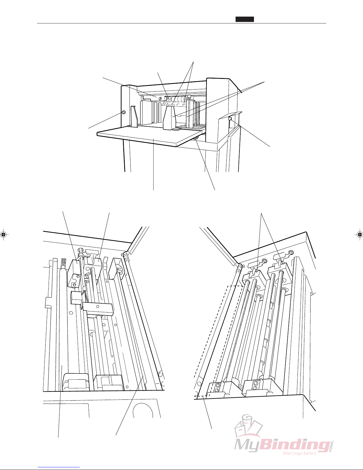
Feeding Section
Separator
Chap.1
c Part Names and Functions
Level ADJ Lever
Blower Air ADJ Knob
CCD
Margin Slitter
Flat Belt
Feed Tray
Guide Plate
Separator ADJ Knob
Skew ADJ Knob
Center Slitter
2nd Roller
Cutter
Creaser
13
Chap.1
c Part Names and Functions
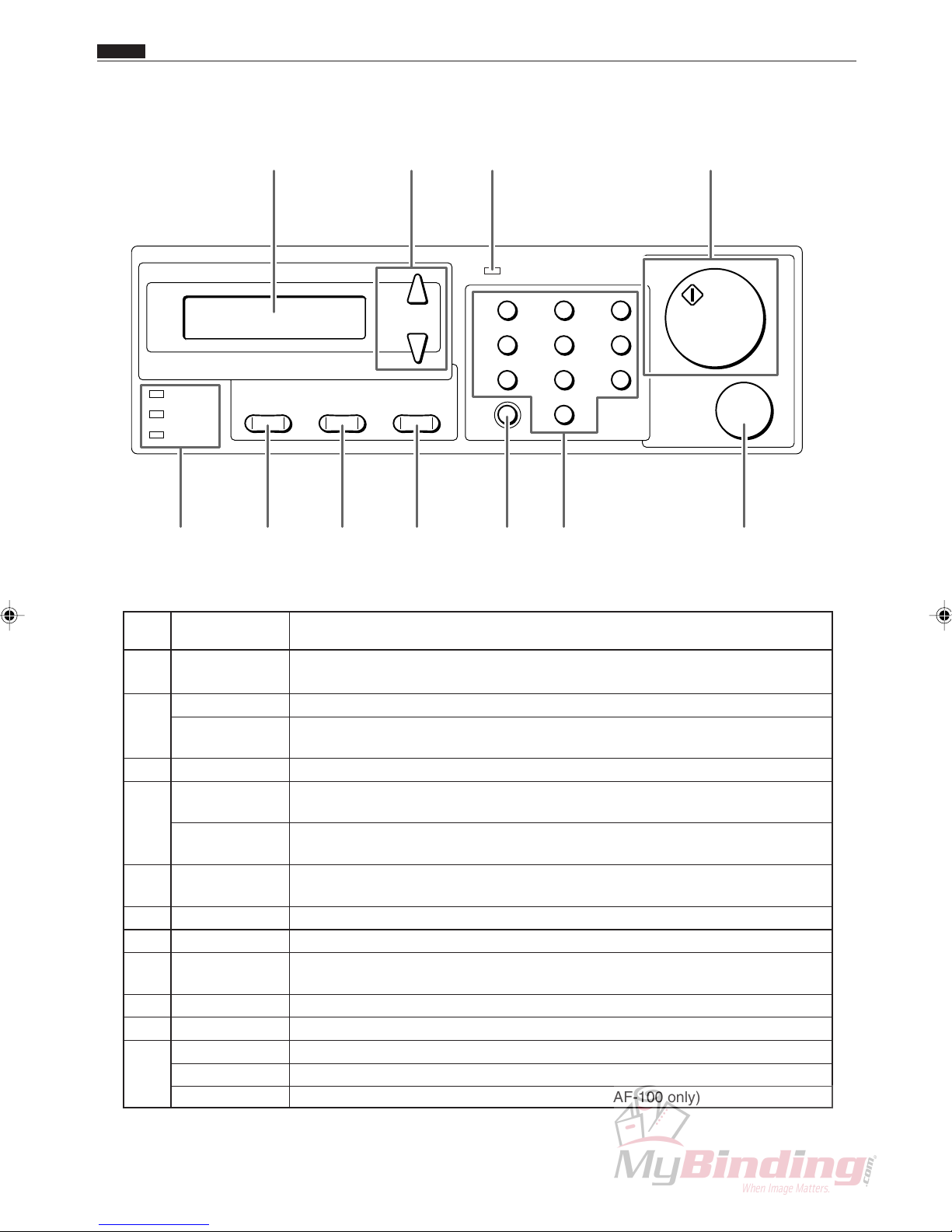
2. Operation Panel
w e rq
START
STOP
COVER
JAM
PAPER
POWER
+
–
F
MODE SET
C
1
4
7
2
5
8
3
6
9
0
!0!1 o i u ty
No. Name Function
q LCD panel Displays the status of the machine.
Displays messages when an error or paper jam occurs.
w <+> key Press to eject the document from the machine at the time of paper jam.
<-> key Press to eject the document from the machine at the time of paper jam. During
programming mode enables backward movement through the program steps.
e POWER lamp Lights up when the power is switched on.
r <START> key Not used when the DC-545 is operated without the autofeeder - AF-100. Press
to start processing when the AF-100 is attached.
START lamp Normally lights up in green. Lights up in red when the front cover or the rear
cover is open.
t <STOP> key Press to stop automatic feeding after the current sheet is processed.
Press to clear jam indication after the paper is cleared.
y Key pad Press to enter print numbers and enter values during manual programming.
u <CLEAR> key Press to clear the count. Press to cancel manual programming.
i <SET> key Press to confirm selection/entry. Used to test process a single sheet. (for
systems with the AF-100 only)
o <MODE> key Press to change the mode.
!0 <F> key The AF-100 Feed Tray lowers while the <F> + <-> keys are being pressed.
!1 COVER lamp Blinks when the front cover or the rear cover is open.
JAM lamp Blinks when a paper jam has occurred.
PAPER lamp Blinks when paper runs out. (systems with the AF-100 only)
14
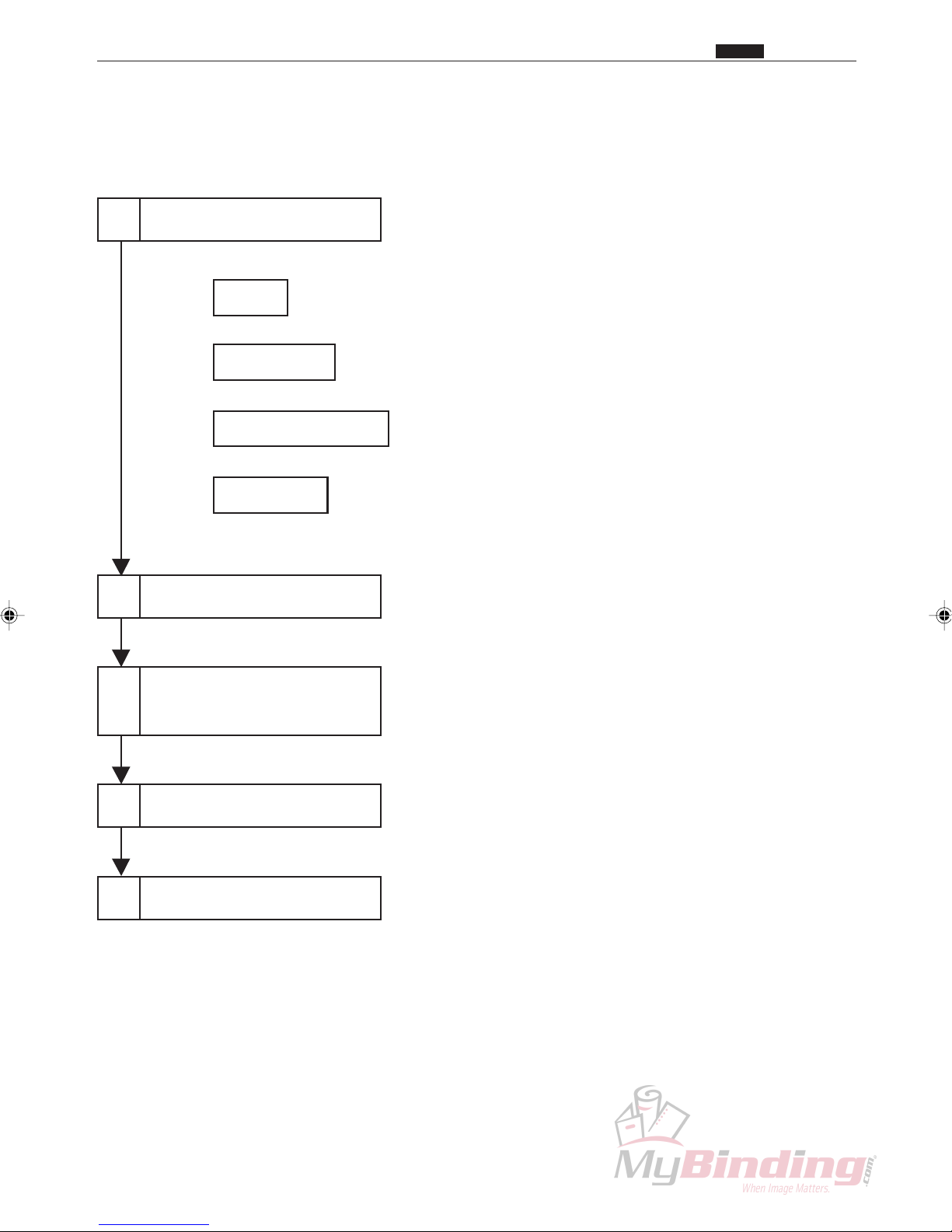
v Work Flow
1. Operations
1
V arious Settings
Chap.1
v Work Flow
INPUT
BAR CODE
REGISTER MARK
AUTO CUT
Setting the paper
2
Select the Program
3
Except when bar code is on.
.....................................How to create job programs
........................ When to use bar codes
............When to use register marks
...........................When to use AUTO CUT
<Start> Key
4
5
Finish
15
Chap.1
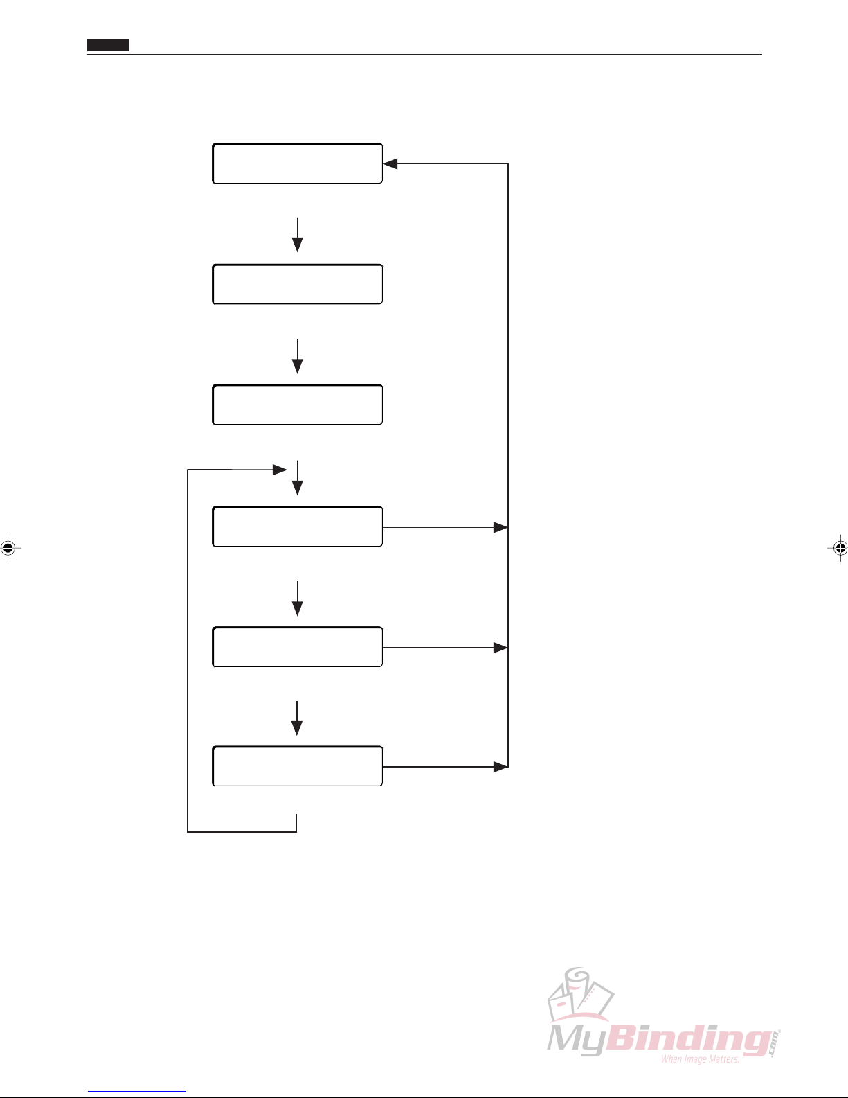
v Work Flow b Options
MODE switching is shown next.
[RUN] P–04
<MODE> KEY
[SELECT] P–04
<MODE> KEY
[INPUT]
––
INPUT
>SET
<MODE> KEY
BARCODE
*ON OFF
<SET> KEY
REGISTER MARK
*ON OFF
<SET> KEY
AUTO CUT
*ON OFF
<SET> KEY
<MODE> KEY
<MODE> KEY
<MODE> KEY
b Options
Setting the Optional Slitter 2
16

17
Chapter 2 Description of Operation
z Paper Feed Unit ......................................... 18
1. Description............................................ 18
2. Operation .............................................. 18
3. Operation of each unit ......................... 19
(1) Fan (Blower) ............................................ 19
(2) Fan (Suction)............................................ 20
(3) Paper Level Sensor .................................. 21
(4) Suction Unit and Feed Motor................... 22
(5) Separator Gap .......................................... 23
(6) Elevator Motor .........................................24
(7) Elevator Upper Switch............................. 25
(8) Elevator Lower Switch ............................ 26
(9) Paper Detection Sensor ............................27
(10) Feed Solenoid ........................................ 28
(11) Feed Stepping Motor.............................. 29
x CCD Mechanism ........................................ 30
1. Description............................................ 30
2. Operation .............................................. 30
c Margin Slitter.............................................. 32
1. Description............................................ 32
2. Operation .............................................. 33
v Guillotine Cutter Unit................................. 34
1. Description............................................ 34
2. Operation .............................................. 34
b Creaser Unit ............................................... 35
1. Description............................................ 35
2. Operation .............................................. 35
n Center Slitter .............................................. 37
1. Description............................................ 37
2. Operation .............................................. 37
m Paper Eject Tray......................................... 39
1. Description............................................ 39
, Main Drive................................................... 40
1. Description............................................ 40
2. Operation .............................................. 41
. Skew Adjustment Mechanism .................. 43
1. Description............................................ 43
⁄0 BAR CODE.................................................. 44
1. Description............................................ 44
⁄1 REGISTER MARK....................................... 45
2
18
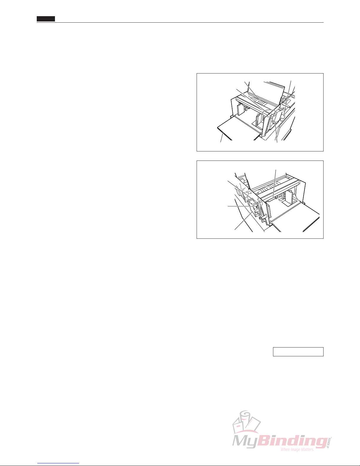
z Paper Feed Unit
1. Description
The paper loaded on the feed tray is raised by the
elevator motor. When the paper is in the required
position, a jet of air from a fan in front of the paper
causes several sheets of paper to rise up. The suction
unit pulls up the top sheet only, and then the feed motor
drives the suction belt to transfer the paper.
When the paper from the AF-100 reaches the PPS1 in
the DC-545, the paper is transferred to the paper path by
the press roller and the feed stepping motor.
A separator mechanism is used to prevent two or more
sheets from being transferred at one time.
Suction Assembly
Feed Tray
Feed Motor
Fan (Suction)
Elevator Motor
Fan (Blower)
Elevator
Upper SW
Elevator
Lower SW
Level Sensor
2. Operation
1) Processing starts (processing does not start if there is no paper).
The fan (blower) and the fan (suction) start running.
2) The feed tray starts rising.
3) The feed tray stops when the paper level sensor turns on (light is not transmitted).
4) The shutter solenoid operates and the shutter opens and the paper is sucked onto the suction unit.
5) The feed motor starts and the suction belt begins turning to transfer the paper.
6) The feed motor stops when the paper reaches PPS1 (light is not transmitted).
If paper does not reach PPS1 within about 2.5 seconds, the elevator falls repeating operations 3) to 5) until
the paper level sensor turns off (light is transmitted). If the operation is repeated three times before the paper
reaches PPS1, a J2: FEED JAM error occurs and the machine stops.
\See page 132
Chap.2
z Paper Feed Unit

19
3. Operation of each unit
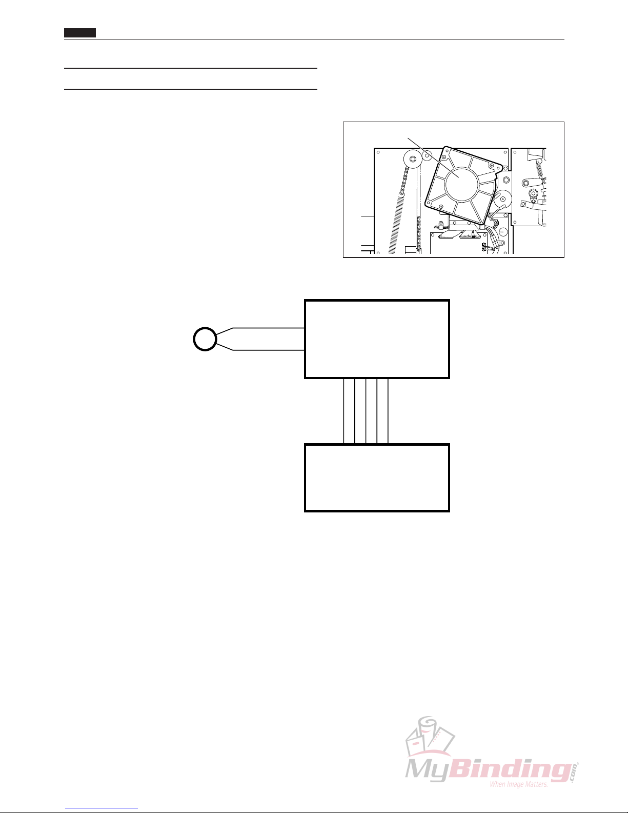
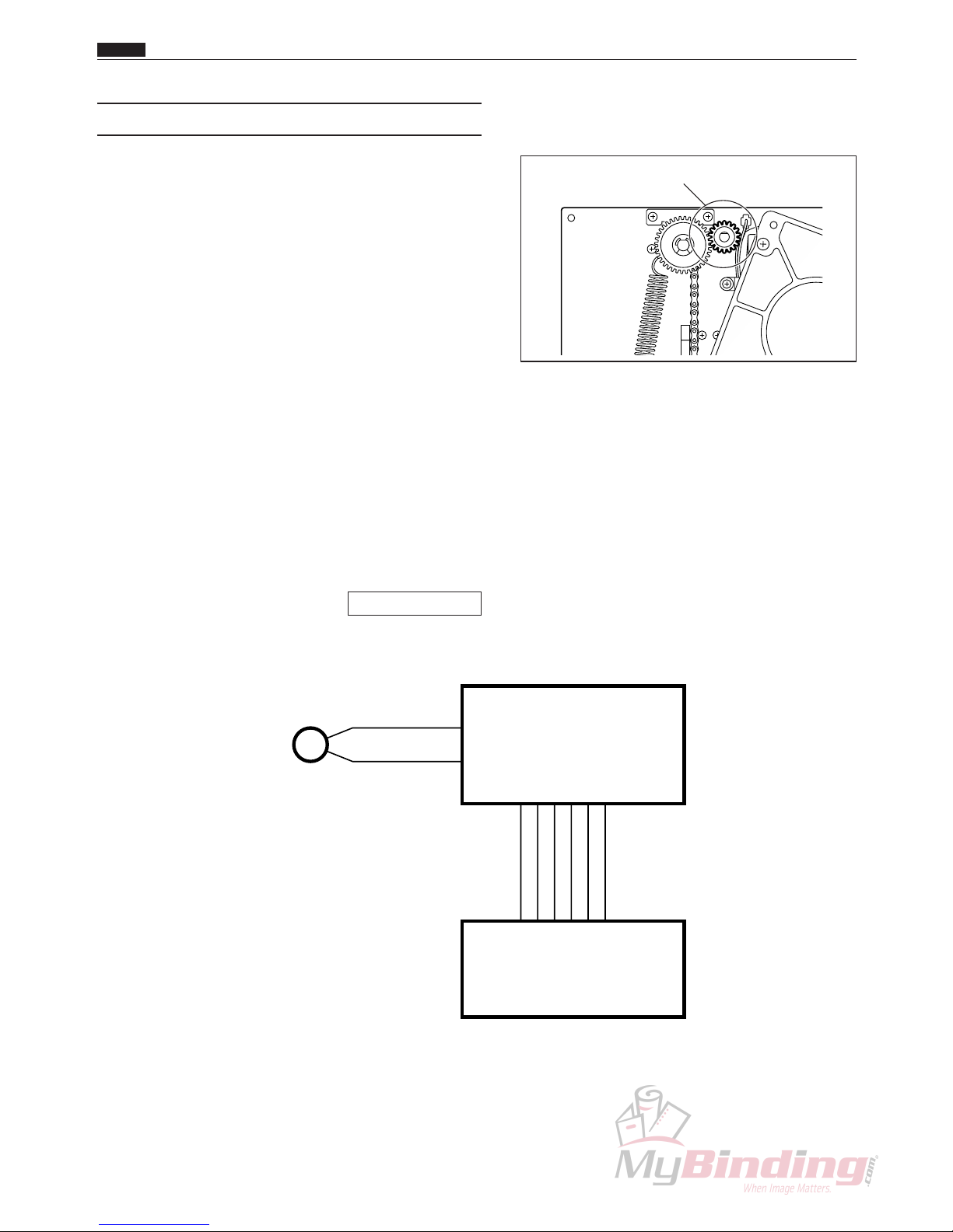
(1) Fan (blower)
Description
Paper on the feed tray is transferred to the blower and several sheets are floated up.
The airflow of the blower is adjusted by changing the position of the shutter and fan unit.
The level the paper is floated up is adjusted by changing the airflow of the blower and the paper level sensor.
The fan (blower) is usually running during processing.
Operation
The blower airflow can be increased by turning the knob so the numbers increase.
The gap between the shutter and the fan increases, which increases the air intake and therefore increases the
amount of air blown out.
The blower airflow can be decreased by turning the knob so the numbers decrease.
The gap between the shutter and the fan decreases, which decreases the air intake and therefore decreases the
amount of air blown out.
Circuit diagram
Shutter
Fan (Blower)
Knob
Chap.2
z Paper Feed Unit
RED
BLACK
CN2-3
24V
FAN(Exhaust)
GND
GND
24V
CN1-1CN1-1
-3
-12
CN11-10
-19
-3
-12
-17
-18
-4
FAN(Blower)
N4-X105*
Feed P.W.B. unit
N4-V303*
Main P.W.B. unit
N4-V300*
M
20
(2) Fan (Suction)
Description
Air near the suction belt is sucked in, and then blown
out on the right side of the AF-100.
The fan (suction) is usually running during processing.
Circuit diagram
Fan(Suction)
Chap.2
z Paper Feed Unit
RED
BLACK
CN3-1
24V
FAN(Intake)
GND
GND
24V
CN1-1CN1-1
-2
-12
CN11-10
-19
-2
-12
-17
-18
-3
FAN(Suction)
N4-X105*
Feed P.W.B. unit
N4-V303*
Main P.W.B. unit
N4-V300*
M
21
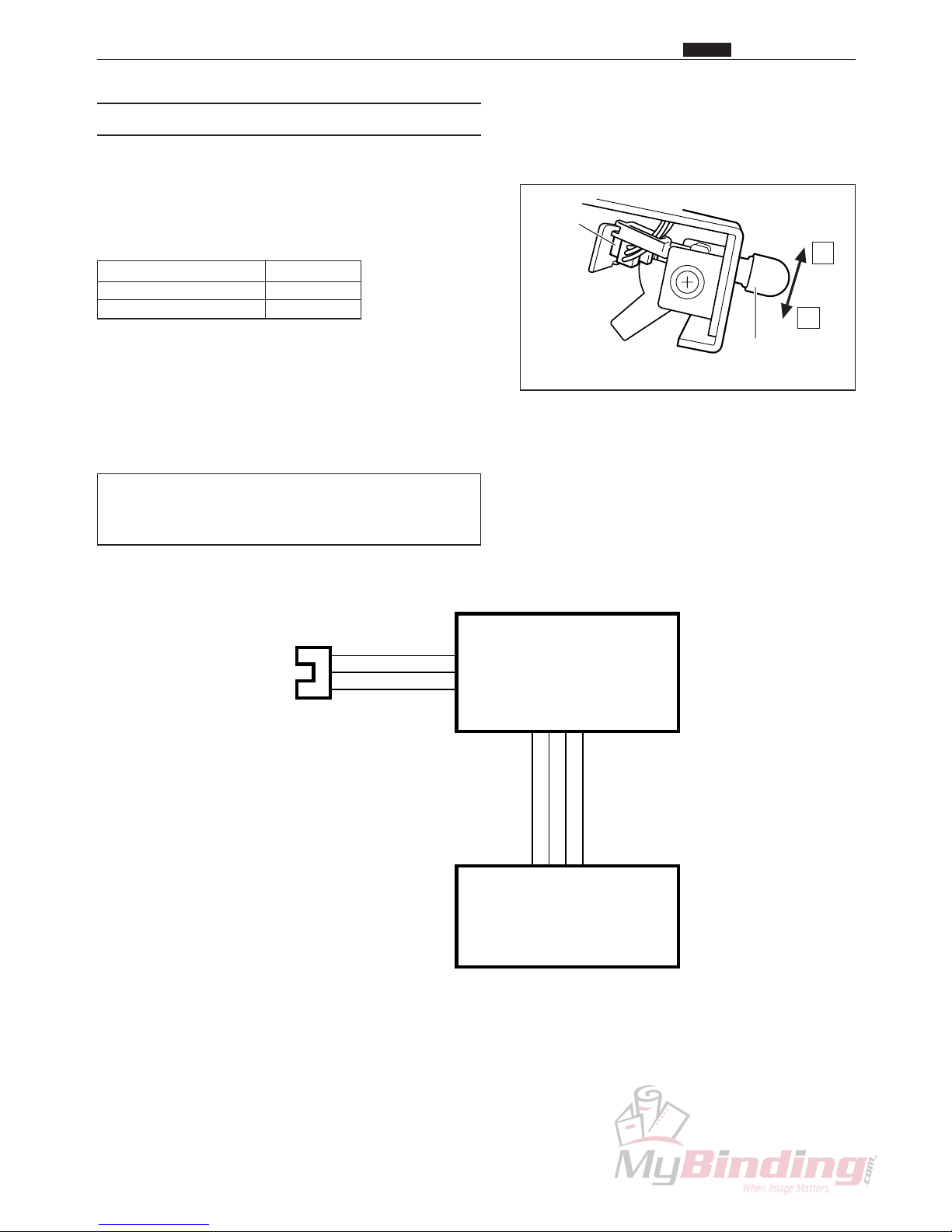
(3) Paper Level Sensor
Description
The paper level sensor controls the elevator motor to
determine the position of the feed tray by detecting the
position of the topmost sheet of paper on the feed tray.
Status Output
Light not transmitted 5V
Light transmitted 0V
To reduce the force of the suction, move the adjustment
lever towards q to increase the gap between the suction
belt and the paper.
To increase the force of the suction, move the
adjustment lever towards w to decrease the gap
between the suction belt and the paper.
Turn the lever towards q if the paper is double feed.
Turn the lever towards w if the paper is not being
sucked on to the suction unit.
Circuit diagram
Chap.2
z Paper Feed Unit
Level
Sensor
q
w
Level Sensor
Adjustment Lever
RED
BLUE
YELLOW
1
3
2
CN4-11
-12
5V
GND
Level Sensor
GND
CN1-11CN1-11
-12
-14
CN11-10
-12
-14
-17
-13
Level Sensor
CA021
Feed P.W.B. unit
N4-V303*
Main P.W.B. unit
N4-V300*

22
Chap.2
z Paper Feed Unit
(4) Suction Unit and Feed Motor
Description
Because the fan (suction) is running during processing,
when the shutter solenoid is on, the topmost sheet of
paper on the feed tray is sucked on to the suction unit.
The feed motor starts running about 0.3 seconds after
the shutter solenoid turns on, and the suction belt turns
and transfers the paper to the DC-545.
Circuit diagram
Shutter (inner)
Shutter Solenoid
RIGHT
BLUE
RIGHT
BLUE
RED
RED
CN2-7
24V
solenoid
Feed
GND
GND
CN1-1CN1-1
-6
-7
CN11-10
-19
-6
-7
-12
-17
24V
-18
-8
Shutter Solenoid
FEED MOTOR
N4-X101*
Feed P.W.B. unit
N4-V303*
Main P.W.B. unit
N4-V300*
SOL
BROWN
BLACK
CN2-9
-10
N4-X104*
M
23
Chap.2
z Paper Feed Unit
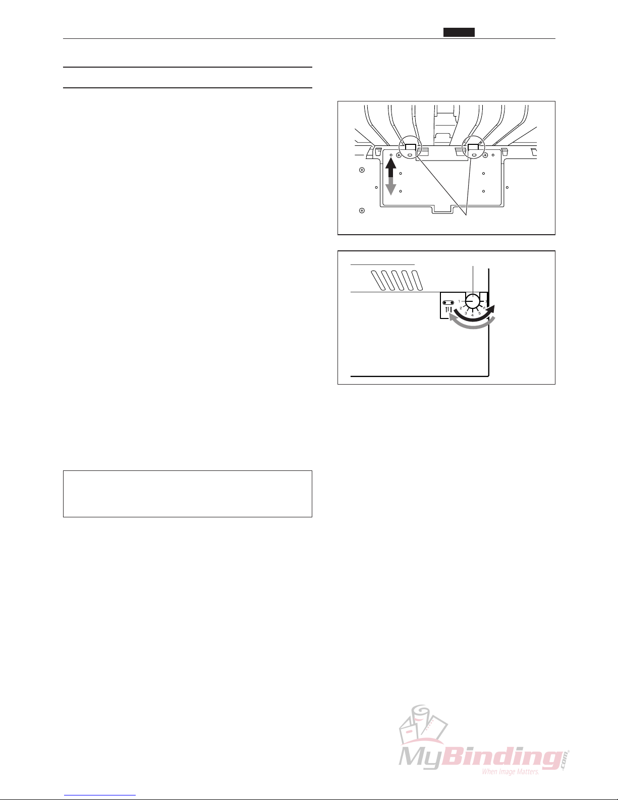
(5) Separator Gap
Description
The separator gap is a mechanism between the separator
and the suction belt that allows paper that is sucked on
to the suction unit to be transferred one sheet at a time
to the paper path.
This gap is regulated by turning the knob to raise and
lower the separator.
Turn the knob so that the numbers increase to make the
gap narrower. The separator rises and the gap narrows.
Turn the knob so that the numbers decrease to make the
gap wider. The separator falls and the gap widens.
Raise the separator if the paper being transferred is
double feed.
Lower the separator if paper is mis-feeding.
Separator
Separator Adjustment Knob
24
Chap.2
z Paper Feed Unit
(6) Elevator Motor
Description
The elevator motor raises and lowers the feed tray.
When there is no paper on the feed tray, the feed tray
lowers until it triggers the elevator lower SW.
However, if paper is loaded on the feed tray while it is
lowering (paper sensor is not transmitting light), the
elevator motor stops and the feed tray stops lowering.
The feed tray rises until the paper level sensor is on
(light is not transmitted) while paper is being fed.
During a paper feed retry operation, the feed tray
continues to lower until the paper level sensor goes off
(light is transmitted) for a period. Then the feed tray
rises until the paper level sensor goes on (light is not
transmitted).
If paper does not reach the elevator upper switch,
elevator lower switch, or paper level sensor after a set
time (*) after the elevator operation, an E8: ELEVATOR
ERROR occurs.
* 10 seconds when rising at start, 3.5 seconds during
paper feed operations, 9 seconds when lowering at
stop
\See page 138
Circuit diagram
Elevator Motor
BROWN
BLACK
CN2-5
24V
ELEVATOR1
ELEVATOR2
GND
GND
24V
CN1-1CN1-1
-4
-5
CN11-10
-19
-4
-5
-17
-18
-6
Elevator Motor
N4-X106*
Feed P.W.B. unit
N4-V303*
Main P.W.B. unit
N4-V300*
M
25
Chap.2
z Paper Feed Unit
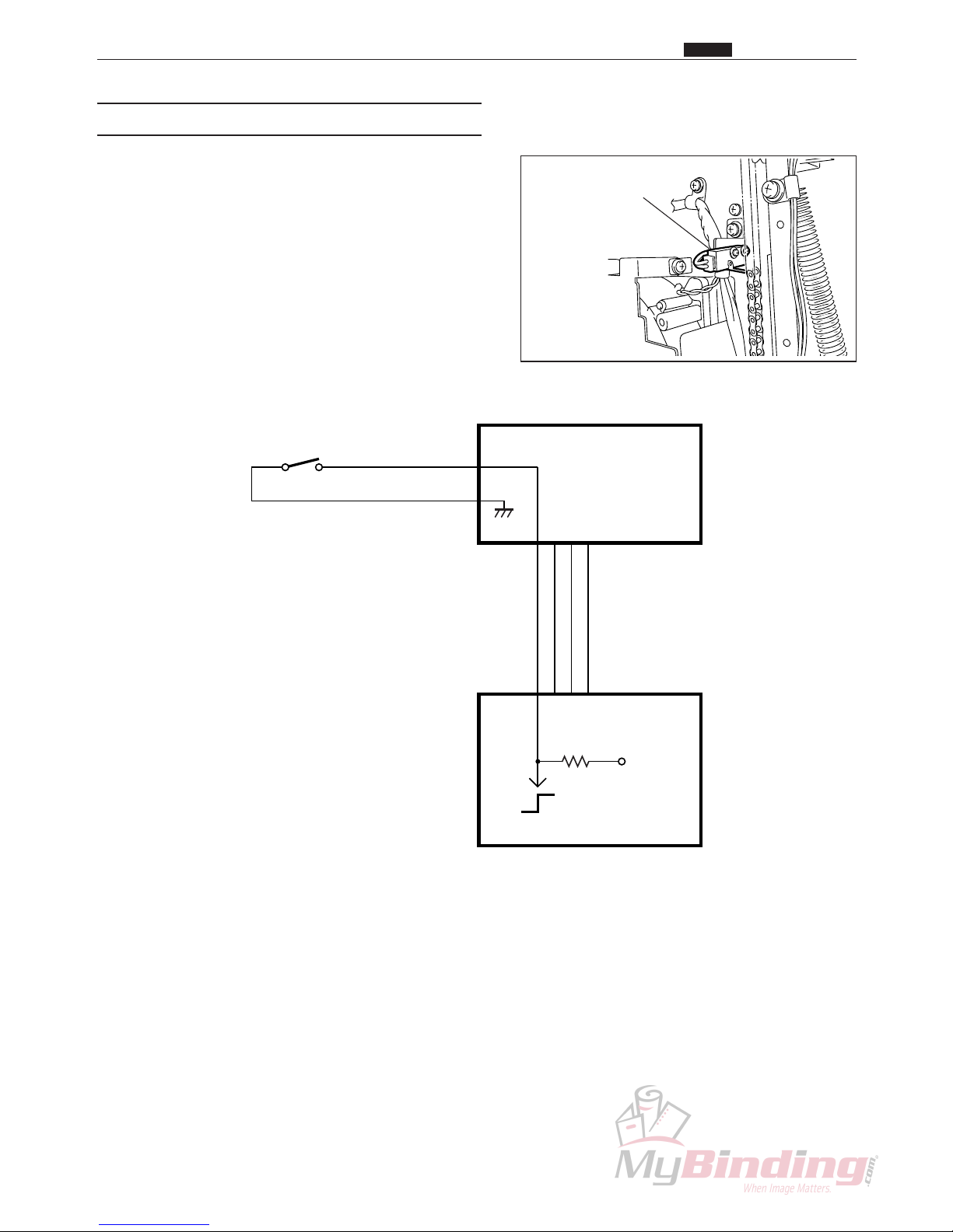
(7) Elevator Upper Switch
Description
The feed tray stops when the angle that is attached to
the chain that raises and lowers the feed tray turns the
micro switch on.
The feed tray is determined to be at its upper limit when
the micro switch is on, and the feed tray will not rise
any higher.
Circuit diagram
Elevator Upper SW
PURPLE
PURPLE
CN4-3
-4
Elevator Upper SW
5V
GND
GND
CN1-9CN1-9
-11
-12
CN11-10
-11
-12
-17
ELEVATOR UPPER SW
LA028
Feed P.W.B. unit
N4-V303*
Main P.W.B. unit
N4-V300*
0
5V5VON:0V
OFF:5V
26
Chap.2
z Paper Feed Unit
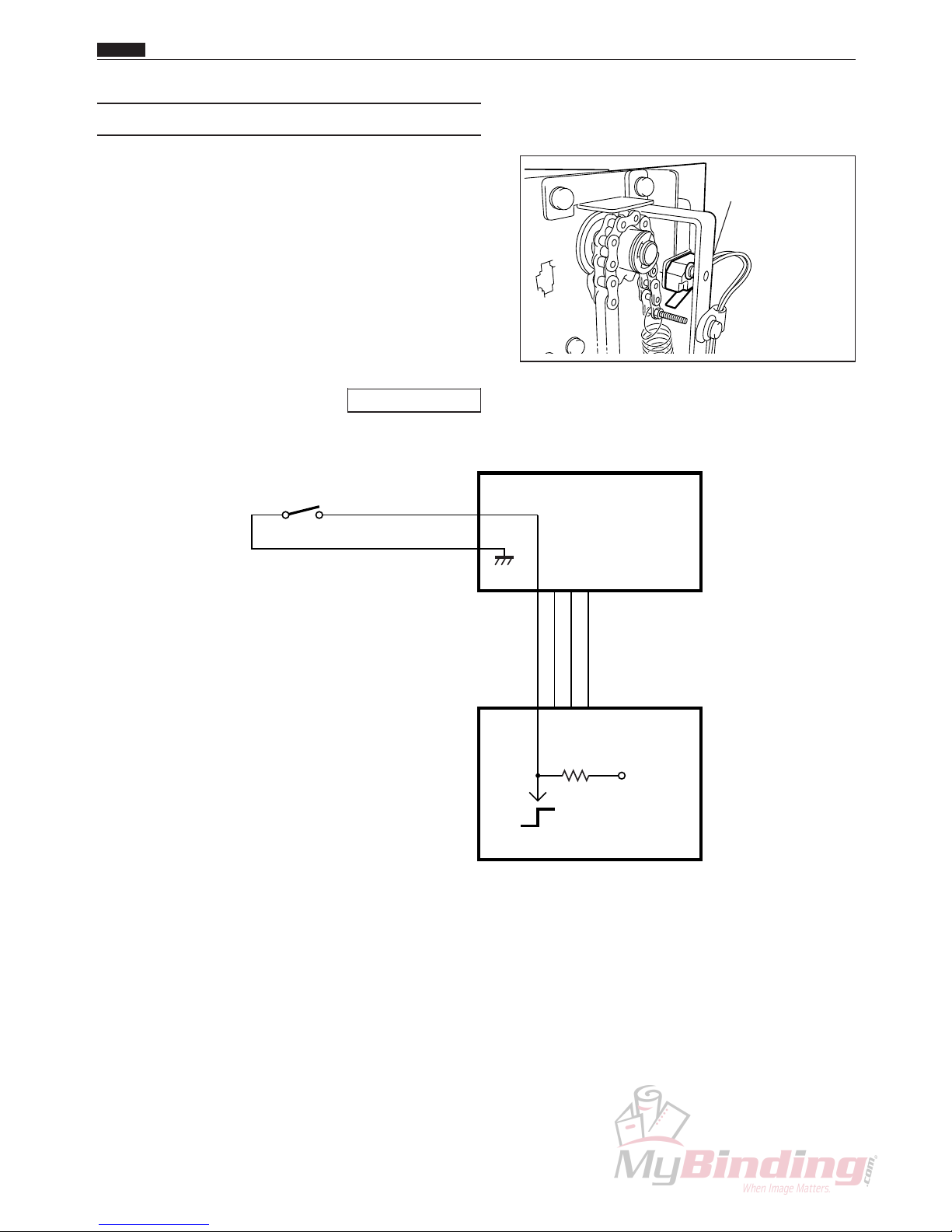
(8) Elevator Lower Switch
Description
The feed tray stops when the screw that is attached to
the chain that raises and lowers the feed tray turns the
micro switch on.
The feed tray is determined to be at its lower limit when
the micro switch is on, and the feed tray will not go any
lower.
If the elevator lower switch is on because there is too
much paper loaded on the feed tray, and the paper level
sensor is on (light is not transmitted), then a J5: OVER
CAPACITY error occurs.
\See page 133
Circuit diagram
Elevator Lower SW
ORANGE
ORANGE
CN4-1
-2
Elevator Lower SW
5V
GND
GND
CN1-10CN1-10
-11
-12
CN11-10
-11
-12
-17
ELEVATOR LOWER SW
LA028
Feed P.W.B. unit
N4-V303*
Main P.W.B. unit
N4-V300*
0
5V5VON:0V
OFF:5V
27
Feed PPS Photo
Diode
Feed PPS Photo
Transistor
Feed PPS Photo
Transistor
Chap.2
z Paper Feed Unit
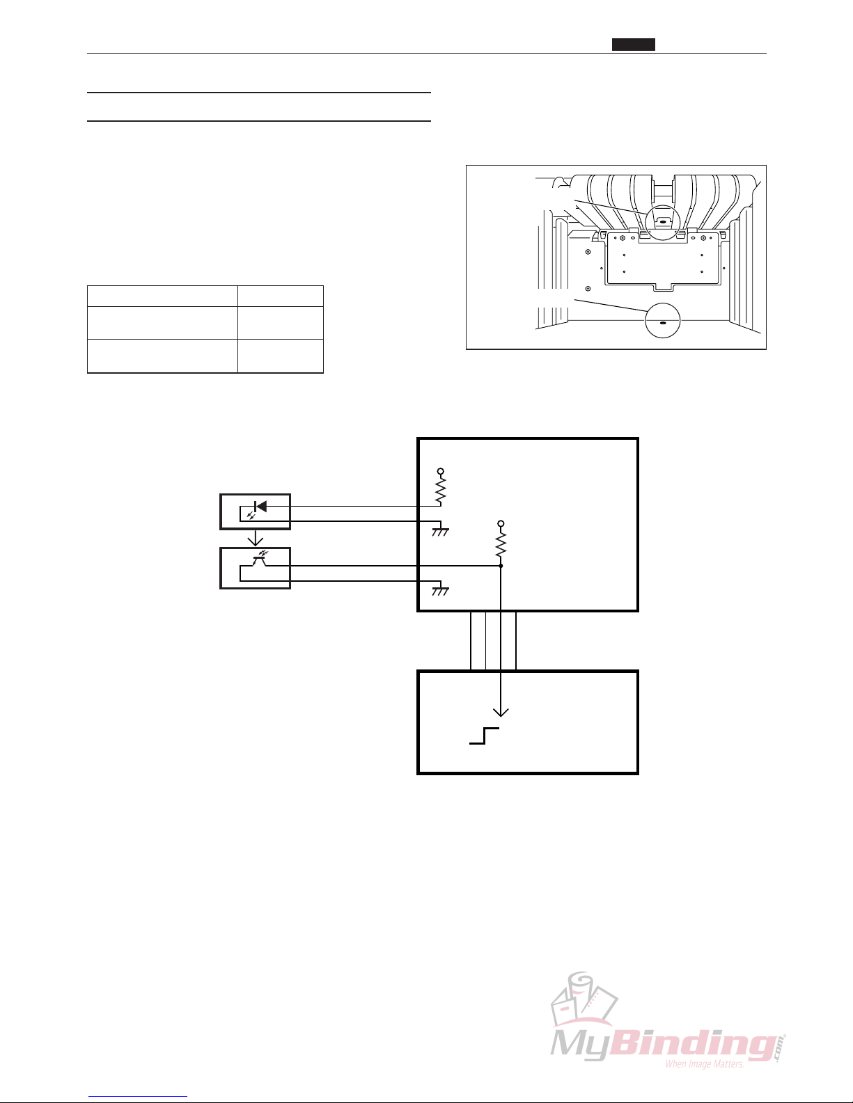
(9) Paper Detection Sensor
Description
The paper detection sensor detects whether or not there
is paper on the feed tray.
If there is no paper, the elevator goes to its lower level
and stops.
When there is not paper (light is transmitted) the LED
(PAPER) on the operation panel blinks.
Status Output
Paper is present
5V
(light is not transmitted)
Paper is not present
0V
(light is transmitted)
Circuit diagram
BROWN
BLUE
CN4-7
-8
5V
GND
Feed PPS
GND
CN1-11CN1-11
-12
-13
CN11-10
-12
-13
-17
Feed PPS Photo Diode
Feed PPS Photo Transistor
N4-W109*
Feed P.W.B. unit
N4-V303*
Main P.W.B. unit
N4-V300*
0
5V
5V
5V
Paper is present :5V
Paper is not present :0V
WHITE
BLUE
CN4-9
-10
N4-W206*

28
(10) Feed Solenoid
Description
Paper that reaches PPS1 is transferred to the paper path
when feeding paper.
As the feed solenoid turns on, the roller driven by the
feed stepping motor presses the paper onto the press
roller and sends it to the main paper path.
Circuit diagram
Feed Solenoid
Chap.2
z Paper Feed Unit
RED
RED
CN6-1
-2
Feed Solenoid
N4-X101*
Main P.W.B. unit
N4-V300*
SOL

29
(11) Feed Stepping Motor
Description
Paper that reaches PPS1 is transferred to the main paper
path.
Circuit diagram
Feed Stepping Motor
CN3-3
-8
FEED STEPPING MOTOR
M7-X111*
Main P.W.B. unit
N4-V300*
M
Chap.2
z Paper Feed Unit

30
x CCD Mechanism
1. Description
The CCD mechanism reads the bar code and register
mark on the paper that is being processed and transfers
the data to the main P.W.B. unit.
The job is automatically selected according to the bar
code (code 39) and the register mark compensates for
incorrect printing positioning.
2. Operation
1) When the paper feeding operation is finished, the
CCD starts reading the bar code.
If the data transfer between the CCD and the main
P.W.B. is not done correctly, then E2: RS232C
ERROR is displayed and the machine stops.
If bar code is off go to Step 4.
\See page 135
2) Data is transferred to the main P.W.B. after the bar
code has been read.
If, when reading starts, the paper is transferred
50 mm but the bar code could not be read, then E3:
BARCODE ERROR is displayed and the machine
stops.
\See page 135
3) The job is set based on the data in the bar code.
4) The machine is in standby until each slitter has been
moved.
If register mark is turned off go to Step 9.
5) The front edge of the paper backs up to PPS2
temporarily.
6) The CCD starts to read the register mark.
7) The amount of compensation is calculated after the
register mark has been read.
If the register mark can not be read even though the
paper has been transferred 40 mm after reading has
started, then E4: REG. MARK ERROR is displayed
and the machine stops.
\See page 135
8) The position of each slitter, cutter and scorer is
adjusted.
9) The CCD processing is finished.
CCD Unit
Chap.2
x CCD Mechanism

31
Chap.2
x CCD Mechanism
CN5-1
CN5-10
Main P.W.B. unit N4-V300*
CCD unit N4-X103*
~
Circuit diagram

32
c Margin Slitter
1. Description
The margin slitter position motor starts, turning the lead
screw, and the margin slitter is moved to the designated
position.
These slitters are used for removing the left and right
margins to the waste tray.
Right Margin Slitter
Left Margin Slitter
Sensor
Right Margin Slitter
Sensor
Left Margin Slitter
Left Margin Slitter Position Motor
Left Margin Slitter
Position Motor
Slitter Driving Motor
Chap.2
c Margin Slitter

33
2. Operation
1) After paper feeding has finished (after the feed
stepping motor stops) the margin slitter returns to the
home position under the following conditions.
q The first process after the power was turned on.
w After all the covers have been opened.
e After the machine stops due to an error.
r There is no paper in the feed tray, after paper is
loaded in the feed tray again.
t After the job has been changed.
2) When the margin slitter moves from the home
position to the position indicated for the job, if the
margin slitter moves 8 mm and light is still not being
transmitted at the slitter sensor, then E5: SLITTER
ERROR is displayed and the machine stops.
\See page 136
Possible range for each slitter
Name Possible range
Left Margin Slitter 0 to 120 mm
Right Margin Slitter 200 to 320 mm
NOTE :
• 3.2 mm is the smallest possible margin
width.
Circuit diagram
Chap.2
c Margin Slitter
CN6-3
-3
-2
CN8-1
3
2
1
BLUE
YELLOW
RED
-6
CN7-1
-4
Main P.W.B. unit
N4-V300*
-23
-22
CN4-21
3
2
1
BLUE
PEACH
RED
M
M
-14
CN3-9
M
~~
Left Margin Slitter Sensor
CA003
Right Margin Slitter Sensor
CA003
Slitter Driving Motor
L8-X1010
Left Margin Slitter Position Motor
M7-X111*
Right Margin Slitter Position Motor
M7-X111*

34
Cutter
Cutter Motor
Cutter Position
Switch
v Guillotine Cutter Unit
1. Description
The paper is cut vertically in relation to the direction the
paper is moving.
Turning on the power starts the cutter motor in standby
in the home position.
One cut can be done in approximately 0.3 seconds.
2. Operation
1) Main transfer stops temporarily when the paper
reaches the cutting position.
2) The cutter motor starts and cutting begins.
3) The cutter motor stops when the cutter position
sensor goes from off to on, and the main transfer
starts again. If the cutter position sensor does not
change (if its on then it stays on) 0.6 seconds after
the cutter motor starts running, then J7: CUTTER
LOCK is displayed and the machine stops.
\See page 134
Circuit diagram
Chap.2
v Guillotine Cutter Unit
CN6-5
-6-7-8
RED
BLACK
RED
BLACK
YELLOW
YELLOW
YELLOW
YELLOW
YELLOW
YELLOW
YELLOW
YELLOW
Main P.W.B. unit
N4-V300*
COVER SW
N4-W120*
COVER SW
N4-W119*
CUTTER UNIT
L8-X109*
CUTTER M.
POSITION SW

35
b Creaser Unit
Chap.2
b Creaser Unit
1. Description
The paper is creased vertically in relation to the direction the paper is moving.
One crease can be done in approximately 1.5 seconds.
Turning on the power starts the creaser motor in standby in the home position.
2. Operation
1) Main transfer stops temporarily when the paper reaches the crease position.
2) The creaser motor starts and cutting begins.
3) The creaser motor stops when the creaser position sensor goes from off to on, and the main transfer starts
again. If the creaser position sensor does not change (if light is transmitted then it continues to transmit) 2.0
seconds after the creaser motor starts running, then J8: CREASE LOCK is displayed and the machine stops.
\See page 134
Creaser Position Sensor
Creaser Unit
Creaser Unit
Creaser Motor

36
Circuit diagram
Chap.2
b Creaser Unit
RED
BLUE
YELLOW
1
3
2
CN8-1
-2
-3
Main P.W.B. unit
N4-V300*
RED
BLACK
CN3-15
-16
CREASER MOTOR
N4-X102*
CREASER SENSOR
CA021
M

37
Chap.2
n Center Slitter
1. Description
The slitter position motor starts, turning the lead screw, and the center slitter is moved to the designated
position and the paper is cut horizontally in reference to the direction the paper is moving.
A maximum of 4 center slitters can be installed.
2. Operation
1) After paper feeding has finished (after the feed stepping motor stops) the center slitter returns to the home
position under the following conditions.
q The first process after the power was turned on.
w After all the covers have been opened.
e After the machine stops due to an error.
r There is no paper in the feed tray, after paper is loaded in the feed tray again.
t After the job has been changed.
2) When the margin slitter moves from the home position to the position indicated for the job, if the margin
slitter moves 8 mm and light is still not being transmitted at the slitter sensor, then E5: SLITTER ERROR is
displayed and the machine stops.
\See page 136
n Center Slitter
OP1 Slitter
Right Center Slitter
Right Center Slitter Sensor
OP2 Slitter Sensor
OP2 Slitter
Left Center Slitter
Left Center Slitter Sensor
OP1 Slitter Sensor
OP1 Slitter
Position Motor
OP2 Slitter
Position Motor
Right Center Slitter
Position Motor
Left Center Slitter
Position Motor
Slitter Driving Motor

38
Chap.2
n Center Slitter
Possible range for each slitter
Name Possible range Comments
Left center slitter 0 to 160 mm Example:
Right center slitter Left center slitter position +50 mm to 320 mm When the left center slitter is set
at 120.2 mm, settings from
170.2 are possible.
OP1 slitter 0 to 320 mm (when OP2 is not installed.)
0 to 160 mm (OP2 is installed)
OP2 slitter OP1 position +50 mm to 320 mm Example:
(This is an optional slitter) When the OP1 is set at 110.0
mm, settings from 160.0 mm are
possible.
Circuit diagram
CN6-9
-9
-8
CN8-7
3
2
1
BLUE
PEACH
RED
-18
CN7-13
-10
Main P.W.B. unit
N4-V300*
-26
-25
CN4-24
3
2
1
BLUE
ORANGE
RED
M
M
-12
CN7-7
M
~~
Left Center Slitter Sensor
CA003
Right Center Slitter Sensor
CA003
Slitter Driving Motor
L8-X1010
Left Center Slitter Position Motor
M7-X111*
Right Center Slitter Position Motor
M7-X111*
-6
CN14-1
-9
-8
CN9-7
3
2
1
BLUE
PURPLE
RED
M
-6
CN9-1
M
~~
OP1 Slitter Sensor
CA003
-9
-8
CN14-7
3
2
1
BLUE
PURPLE
RED
OP2 Slitter Sensor
CA003
OP1 Slitter Position Motor
M7-X111*
OP2 Slitter Position Motor
M7-X111*

39
Chap.2
m Paper Eject Tray
m Paper Eject Tray
1. Description
Paper that is ejected from the DC-545 is collected here.
It is possible to adjust the paper being ejected into two
levels. Refer to the image below for the installation
position.
Position
A
Ejected
amount.......too small
B
Ejected
amount.......too large
A
B

40
, Main Drive
1. Description
The paper is transferred by the main motor.
All the rollers except the rollers driven by the feed
stepping motor use two timing belts driven by the main
motor.
Chap.2
, Main Drive
Main Motor Main Motor Driver
PPS4 Photo Diode
PPS4 Photo Transistor
PPS3 Photo Diode
PPS2 Photo
Transistor
PPS1 Photo
Transistor
PPS3 Photo
Transistor
PPS2 Photo
Diode
PPS1 Photo Diode

41
2. Operation
1) After paper stops being fed (after the Feed Stepping Motor stops) the Main Motor starts running and the
paper is transferred to the paper path section.
2) The paper stops temporarily at the CCD and then continues being transferred. If read BAR CODE
(REGISTER MARK) has been set, then the paper continues being transferred after the BAR CODE
(REGISTER MARK) has been read.
3) Main motor stops temporarily when cutting and scoring. When cutting and scoring have finished, transfer
starts again, and stops a short period after the paper is ejected.
The below two conditions cause J3: CENTER JAM to be displayed, and the machine to stop.
\See page 133
Chap.2
, Main Drive
q When paper does not reach PPS3 (PPS3 is not
transmitting light) although the paper has
transferred 100 mm from after the front edge of
the paper has reached PPS2 (PPS2 is not
transmitting light).
w When paper is not extracted from PPS3 (PPS3 is
not transmitting light) although the total length of
the paper +30 mm has been transferred from after
the front edge of the paper has reached PPS3
(PPS3 is not transmitting light).
No
No
No
Yes
Yes
Yes
J3:CENTER JAM
Start Processing
Has the paper reached
PPS2?
Has the paper reached
PPS3?
Count start
Go to the next path
Has the paper been
transferred 100 mm?
Start processing
Count start
Go to the next path
No
No
No
Yes
Yes
J3:CENTER JAM
Yes
Has the paper reached
PPS3?
Has the paper
separated from PPS3?
Has the paper being
processed been tranferred
a distance more than the
total length of the paper
plus 30 mm?

42
q When paper does not reach PPS4 (PPS4 is not
transmitting light) although the paper has
transferred 500 mm from after the front edge of
the paper has reached PPS3 (PPS3 is not
transmitting light).
The below two conditions cause J4: SLITTER OR STACK to be displayed, and the machine to stop.
\See page 133
w When paper is not extracted from PPS4 (PPS4 is
not transmitting light) although the total length of
the paper +50 mm has been transferred from after
the front edge of the paper has reached PPS4
(PPS4 is not transmitting light).
No
No
No
Yes
Yes
Yes
J4:SLITTER OR STACK
Start processing
Count start
Go to the next path
Has the paper reached
PPS3?
Has the paper reached
PPS4?
Has the paper been
transferred 500 mm?
No
No
No
Yes
Yes
Yes
J4:SLITTER OR STACK
Start processing
Count start
Go to the next path
Has the paper reached
PPS4?
Has the paper
separated from PPS4?
Has the paper being
processed been tranferred
a distance more than the
total length of the paper
plus 50 mm?
Circuit diagram
Main P.W.B. unit
N4-V300*
M
-11
CN1-1
~
-5
CN2-1
~
-12
CN1-1
~
BROWN
BLUE
5V 5V
WHITE
BLUE
CN4-13
-14
-15
-16
PPS4 Photo Transistor
N4-W108*
PPS4 LED
N4-W123*
BROWN
BLUE
5V 5V
WHITE
BLUE
CN4-9
-10
-11
-12
PPS3 Photo Transistor
N4-W111*
PPS3 LED
N4-W110*
BROWN
BLUE
5V 5V
WHITE
BLUE
CN4-5
-6
-7
-8
PPS2 Photo Transistor
N4-W110*
PPS2 LED
N4-W109*
BROWN
BLUE
5V 5V
WHITE
BLUE
CN4-1
-2
-3
-4
PPS1 Photo Transistor
N4-W108*
PPS1 LED
N4-W109*
MAIN MOTOR
M2-X1010
STEPPING DRIVER
L8-X1080
Chap.2
, Main Drive

43
. Skew Adjustment Mechanism
1. Description
If the paper is skewed while processing , use the adjustment knob to adjust the guide and straighten paper.
Adjustment procedure
qw
Turning the knob Turning the knob clockwise
counterclockwise
Angle
Chap.2
. Skew Adjustment Mechanism

44
⁄0 BAR CODE
1. Description
This machine uses code 39 bar code.
Example: The bar code for P-11 is shown below.
The DC-545 can use this bar code if it is converted to CODE-39.
If the bar code comes in the following range, the CCD automatically replaces the data and sends the data (pre-
set no.) to the DC-545.
START/STOP bit
*
112
*
Preset no. Check digit
Code-39
BAR CODE
8 mm
60 mm
Within 35 mm
Paper feeding Direction
8 mm
Chap.2
⁄0 BAR CODE

45
⁄1 REGISTER MARK
Mark 1
1) The paper is transferred in increments of 0.1 mm
from PPS2, and the mark is read by the CCD.
2) When the edge of the reg. mark is detected, the
reference clock count in the CCD is stored in the
buffer in the microcomputer.
3) After another 0.1 mm is transferred, it is compared
with the clock count before the position of the edge is
detected, and if it is within a fixed range, the count is
then +1, and the reference clock in the CCD is stored
in the microcomputer buffer (up to 10 items). The
count is cleared if it is outside the range.
4) When the counter reaches 45 (the edge is the same
for 4.5 mm) the value for the mark is the average of
the values of the 10 values for the reference clock in
the buffer in the CCD.
MARK1
MARK2
10 mm
The clock count within 10 mm in
this space is 70.
CCD Reading Range
Paper Feeding
Direction
Basic clock
in the CCD
Read data
in the CCD
Mark 2
1) The edge of the REGISTER MARK is detected.
2) The paper is transferred in increments of 0.1 mm, and
the mark is read by the CCD. If the REGISTER
MARK has the position of the detected edge (it is
OK even if it is not the edge), if the counter is not +1,
the counter goes to 0 and returns to Step 1.
3) The position of mark 2 is determined as 1.0 mm
before the position when a continuous count of 10
(1.0 mm) is read for the REGISTER MARK.
0.1 mm
1.0 mm
REG.MARK Edge
Chap.2
⁄1 REGISTER MARK

46
* The width of Reg. Mark line is 0.4 mm or more.
* a<=b
Positioning REGISTER MARK and BAR CODE
5 mm
BAR CODE
REG. MARK
*
a
*b
REG. MARK Position range
60 mm or less
35 mm or less
10 mm or more
5 mm
30 mm
8 mm
8 mm
40 mm
* 0.4 mm or
more
5 mm
or more
5 mm or more
8 mm or
more
Chap.2
⁄1 REGISTER MARK

Chapter 3 Mechanical
z Exterior ....................................................... 49
(1) Removing the AF 100 Cover R Unit ............. 49
(2) Removing the AF 100 Cover L Unit ............. 49
(3) Removing the DC 545 Cover R Unit ............ 49
(4) Removing the DC 545 Cover L Unit ............. 50
(5) Removing the Lid .......................................... 50
(6) Removing the Front Cover Switch ................ 50
(7) Removing the Rear Cover Switch ................. 51
x Feed Section .............................................. 52
(1) Removing the AF 100 .................................... 52
(2) Removing the Suction Assembly ................... 53
(3) Removing the Flat Belts ................................ 53
(4) Removing the Fan Motor (Blower) ............... 53
(5) Removing the Feed PCB Unit ....................... 54
(6) Removing the Separator ................................. 54
(7) Removing the Elevator Upper Switch ........... 54
(8) Removing the Elevator Lower Switch ........... 55
(9) Removing the Paper Level Sensor ................. 55
(10) Removing the Feed Motor ........................... 56
(11) Removing the Shutter Solenoid ................... 56
(12) Removing the Shutter .................................. 57
(13) Removing the AF 100 Cover Switch ........... 58
(14) Removing the Elevator Motor ..................... 58
(15) Removing the Fan Motor (Suction) ............. 58
c CCD Section ............................................... 59
(1) Removing the CCD Sensor ............................ 59
v Margin Slitter Section................................ 60
(1) Removing the Margin Slitter
Driving Motor ................................................ 60
(2) Removing the Right Margin Slitter Position
Motor ............................................................. 60
(3) Removing the Left Margin Slitter Position
Motor ............................................................. 61
(4) Removing the Right Margin
Slitter Sensor .................................................. 62
(5) Removing the Left Margin
Slitter Sensor .................................................. 62
(6) Removing the Right Margin Slitter................ 63
(7) Removing the Left Margin Slitter .................. 64
(8) Removing the Margin Slitter’s
Upper Blade ................................................... 65
(9) Removing the Margin Slitter’s
Lower Blade ................................................... 66
b Cutter Section ............................................ 67
(1) Removing the Cutter Assembly ..................... 67
(2) Removing the Cutter Motor ........................... 67
(3) Removing the Cutter Position Switch ............ 68
n Creaser Section ......................................... 69
(1) Removing the Creaser Motor ......................... 69
(2) Removing the Creaser Sensor ........................ 69
(3) Removing the Creaser Assembly ................... 70
m Center Slitter Section ................................ 71
(1) Removing the Center Slitter
Drive Motor ................................................... 71
(2) Removing the Center Right Slitter
Positioning Motor .......................................... 71
(3) Removing the Center Left Slitter
Positioning Motor .......................................... 71
(4) Removing the Optional Slitter 1
Positioning Motor .......................................... 72
(5) Removing the Optional Slitter 2
Positioning Motor .......................................... 72
(6) Removing the Center Right
Slitter Sensor .................................................. 73
(7) Removing the Center Left Slitter Sensor ....... 73
(8) Removing the Optional Slitter 1 Sensor ........ 74
(9) Removing the Optional Slitter 2 Sensor ........ 74
(10) Removing the Center Right Slitter and the
Center Left Slitter ........................................ 75
(11) Removing the Optional Slitter 1 and the
Optional Slitter 2 .......................................... 76
(12) Removing the Center Slitter’s
Upper Blade ................................................. 77
(13)
Removing the Center Slitter’s Lower Blade ...
78
3
47

, Driving Section .......................................... 79
(1) Removing the Main Motor ............................ 79
(2) Removing the Feed Stepper ........................... 79
(3) Removing the 1st Roller (Lower) .................. 80
(4) Removing the 2nd and 3rd Rollers
(Lower) .......................................................... 80
(5) Removing the 4th Roller (Lower) .................. 81
(6) Removing the 5th Roller (Lower) .................. 82
(7) Removing the 6th and 7th Rollers
(Lower) .......................................................... 83
(8) Removing the 8th Roller (Lower) .................. 84
. Electric Section.......................................... 85
(1) Removing the PPS1 Phototransistor .............. 85
(2) Removing the Panel PWB Unit ..................... 85
(3) Removing the Motor Driver .......................... 86
(4) Removing the PPS2 Phototransistor and
PPS3 Photodiode ........................................... 86
(5) Removing the PPS1 and PPS2
Photodiode ..................................................... 87
(6) Removing the PPS3 Phototransistor .............. 88
(7) Removing the Feed Solenoid ......................... 89
(8) Removing the Gate Solenoid
(Without using the DC 545HC) .................... 89
(9) Removing the Main P.W.B. Unit ................... 90
(10) Removing the Power Supply, Power Board,
and Memory Board ...................................... 90
48

z Exterior
(1) Removing the AF-100 Cover R Unit
Chap.3
z Exterior
q Remove the AF-100 from the stand.
\See page 52
w Take out the 4 screws, and remove the cover R unit.
(2) Removing the AF-100 Cover L Unit
q Remove the AF-100 from the stand.
\See page 52
w Take out the 4 screws, and remove the cover L unit.
(3) Removing the DC-545 Cover R Unit
Cover R UnitCover L Unit
ScrewsScrews
q Remove the AF-100 from the stand.
\See page 52
w Take out the 4 screws, and remove the auxiliary
plate.
e Take out the 4 screws, and remove the cover R unit.
NOTE :
• Be sure to attach the auxiliary plate after
attaching the cover.
Auxiliary Plate
Screws
49

Chap.3
z Exterior
(4) Removing the DC-545 Cover L Unit
q Remove the AF-100 from the stand.
\See page 52
w Take out the 4 screws, and remove the cover L unit.
(5) Removing the Lid
q Take out the 6 screws, and remove the lid.
Screws Screws
Cover
L Unit
Screws
Cover
R Unit
Screws
(6) Removing the Front Cover Switch
q Remove the cover R unit from the DC-545.
\See page 49
w Remove the cutter motor.
\See page 67
e Remove the connector for the switch. (2 positions)
r Take out the 2 screws, and remove the front cover
switch.
Reinstallation
Front Cover
Switch Screws
Lid
Screws
Rear Cover
Switch Screws
IMPORTANT:
• Adjust the position in which to install the
cover switch.
\See page 112
50

(7) Removing the Rear Cover Switch
q Remove the cover R unit from the DC-545.
\See page 49
w Remove the cutter motor.
\See page 67
e Remove the connector. (1 position)
r Take out the 2 screws, and remove the rear cover
switch.
Reinstallation
IMPORTANT:
• Adjust the position in which to install the
cover switch.
\See page 112
Front Cover
Switch Screws
Chap.3
z Exterior
Rear Cover
Switch Screws
51

Chap.3
x Feed Section
x Feed Section
(1) Removing the AF-100
q Take out the two screws.
NOTE :
• The machine made to U.S. specifications has
no screws.
w Remove the DC-545 and AF-100 connector.
IMPORTANT:
• Be sure to remove the power cord from the
electric outlet before starting work. Not
doing so may damage the main P.W.B. unit.
Screws
WARNNG
e Remove the AF-100.
52

(2) Removing the Suction Assembly
q Take out the 2 screws, and remove the joint.
w Remove the thumb screw and connector. (1 each)
Chap.3
Joint & Screws
x Feed Section
e Remove the suction assembly.
(3) Removing the Flat Belts
q Remove the suction assembly.
\See page 53
w Slide the flat belts off to remove them.
Thumb Screw
Connector
Flat Belts
(4) Removing the Fan Motor (Blower)
q Remove the AF-100 cover L unit.
w Remove the connector for the fan motor. (1 position).
e Remove the spring.
r Take out the 2 screws, and remove the shutter.
t Remove the 4 screws, and remove the fan motor
(blower).
\See page 49
53
Connector
Fan Motor
Shutter
Screws
Screws
Screws
Spring

Chap.3
x Feed Section
(5) Removing the Feed PCB Unit
q Remove the AF-100 cover R unit.
\See page 49
w Remove the connector for the feed PCB unit.
(4 positions)
e Take out the 4 screws, and remove the feed PCB
unit.
(6) Removing the Separator
Screws
q Remove the suction assembly.
\See page 53
w Take out the 2 screws, and remove the separator.
(7) Removing the Elevator Upper Switch
q Remove the AF-100 cover L unit.
\See page 49
w Remove the connector for the upper switch.
(1 position)
e Take out the 2 screws, and remove the angle.
r Take out the 2 screws, and remove the elevator
upper switch.
Upper Angle
& Screws
Connector
Separator
Screws
Lower Angle
& Screws
Connector
Elevator Lower
Switch
Reinstallation
IMPORTANT:
• Adjust the position in which to install the
upper switch.
\See page 111
54

(8) Removing the Elevator Lower Switch
Chap.3
x Feed Section
q Remove the AF-100 cover L unit.
\See page 49
w Remove the connector for the lower switch.
(1 position).
e Take out the 2 screws, and remove the angle.
r Take out the 2 screws, and remove the elevator
lower switch.
Reinstallation
IMPORTANT:
• Adjust the position in which to install the
lower switch.
\See page 111
(9) Removing the Paper Level Sensor
q Open the cover of the AF-100.
Upper Angle
& Screws
Connector
Lower Angle
& Screws
Connector
Elevator Lower
Switch
w Remove the connector from the inside of the frame.
(1 position)
e Take out the 3 screws, and remove the plate unit.
r Remove the connector for the sensor, and then
remove the paper level sensor.
Connector
Screws
Connector
Sensor
55

Chap.3
x Feed Section
(10) Removing the Feed Motor
q Remove the AF-100 cover R unit.
\See page 49
w Remove the connector for the motor. (1 position)
e Take out the 4 screws, and remove the bracket.
r Loosen the set screws, and remove the pulley unit.
t Take out the 3 screws, and remove the feed motor.
Connector
Screws
Blacket & Screws
Blacket & Screws
Pulley Unit & Set Screw
(11) Removing the Shutter Solenoid
q Remove the suction assembly.
\See page 53
w Take out the 2 screws, and remove the lid.
Lid
Screws
56

Chap.3
x Feed Section
e Remove the connector for the solenoid. (1 position)
r Remove the wire unit from the spring.
t Loosen the set screws on the shaft, and remove the
wire unit.
y Take out the 2 screws, and remove the shutter
solenoid.
Reinstallation
IMPORTANT:
• Adjust the shutter position when install
the shutter solenoid.
\See page 113
(12) Removing the Shutter
q Remove the Shutter Solenoid.
\See page 56
Shaft &
Set Screw
Screws
Shutter
Solenoid
ConnectorSpringWire Unit
Lid & Screws Plate & Screws
w Take out the 4 screws, and remove the plate.
e Take out the 8 screws, and remove the lid.
r Take out the 2 screws, and remove the shutter.
Reinstallation
IMPORTANT:
• Adjust the shutter position when install
the shutter solenoid.
\See page 113
Shutter
Lid & Screws
Screws
57

Chap.3
x Feed Section
(13) Removing the AF-100 Cover Switch
q Remove the AF-100 cover L unit.
\See page 49
w Remove the connector for the switch. (1 position)
e Take out the 2 screws, and remove the AF-100 cover
switch.
Reinstallation
IMPORTANT:
• Adjust the position in which to install the
AF-100 cover switch.
\See page 112
(14) Removing the Elevator Motor
q Remove the AF-100 cover R unit.
\See page 49
w Loosen the set screws, and remove the motor gear.
e Take out the 3 screws, and remove the motor.
Screws
Connector
Screws Connector
r Remove the connector from inside the frame.
(1 position)
(15) Removing the Fan Motor (Suction)
q Remove the AF-100 cover R unit.
\See page 49
w Remove the connector for the fan motor. (1 position)
e Take out the 3 screws, and remove the fan motor.
Screws
Set Screw
Fan Motor
Connector
58

c CCD Section
(1) Removing the CCD Sensor
q Remove the cover L unit from the DC-545.
\See page 50
w Take out the 6 screws, and remove the lid.
\See page 50
e Remove the connector for the main PWB CN5.
(1 position)
r Cut the tie wraps. (4 positions)
NOTE :
• Do not cut any other bundles of wires.
Tie Wrap
Chap.3
c CCD Section
t Remove the code band. (6 positions)
y Cut the tie wraps. (7 positions)
NOTE :
• Do not cut any other bundles of wires.
u Take out the 2 screws, and remove the CCD sensor.
Reinstallation
IMPORTANT:
• Make adjustments after installing the
CCD sensor.
\See page 102, 109
Tie Wrap
Screws
Tie Wrap
Tie Wrap
CCD
Paper
59

Chap.3
v Margin Slitter Section
v Margin Slitter Section
(1)
Removing the Mar gin Slitter Driving Motor
q Remove the cover R unit from the DC-545.
\See page 49
w Take out the 2 screws, and remove the bundled cable
plate.
Timing Belt
e Take out the 4 screws, and remove the margin slitter
driving motor.
r Remove the timing belt.
t Extract the motor, and remove the connector.
(1 position)
y Take out the set screw, and remove the pulley unit.
u Take out the 3 screws, and remove the margin slitter
driving motor.
(2) Removing the Right Margin Slitter
Position Motor
q Remove the cover R unit from the DC-545.
\See page 49
Bundled Cable Plate
Margin Slitter Driving Motor Assembly
Pulley Unit & Set Screw
Screws
Control Plate Assembly
Screws
Screws
w Take out the 4 screws, and remove the panel bracket.
e Take out the 4 screws, and remove the right margin
slitter position motor.
r Remove the connector for the motor. (1 position)
Connector
Screws
60

(3) Removing the Left Margin Slitter
Position Motor
q Remove the cover L unit from the DC-545.
\See page 50
w Take out the 6 screws, and remove the lid.
\See page 50
Chap.3
v Margin Slitter Section
e Open the door in the stand, and remove the waste
tray.
r Take out the 2 screws, and remove the cover.
t Undo the thumb screws, and remove the guide unit.
y Remove the connector for the motor. (1 position)
u Take out the 4 screws, and remove the left margin
slitter position motor.
Thumb
Screws
Guide Unit
Screws
Guide
Screws Cover
61

Chap.3
v Margin Slitter Section
(4) Removing the Right Margin Slitter
Sensor
q Open the cover (front) of the DC-545.
w Remove the connector for the sensor. (1 position)
Sensor
e Remove the right margin slitter sensor from the
angle.
Reinstallation
IMPORTANT:
• Make adjustments after installing the
sensor.
\See page 95
Optional 1 Slitter Sensor Optional 2 Slitter Sensor
Center Left Slitter Sensor Center Right Slitter Sensor
This image shows the right margin slitter sensor.
Angle
Connector
Left Margin Slitter Sensor Right Margin Slitter Sensor
Feed Direction
DC-545 Position Sensor Layout
(5) Removing the Left Margin Slitter
Sensor
q Open the cover (front) of the DC-545.
w Remove the connector for the sensor. (1 position)
e Remove the left margin slitter sensor from the angle.
Reinstallation
IMPORTANT:
• Make adjustments after installing the
sensor.
\See page 95
62

(6) Removing the Right Margin Slitter
Chap.3
v Margin Slitter Section
q Remove the cover R unit from the DC-545.
\See page 49
w Take out the screw, and remove the clamper.
(2 positions)
e Loosen the 4 screws and slide the motor plate
towards the exit tray.
r Face the key groove on the shaft downwards, and
pull it out on the operation side. (2 positions)
NOTE :
• Do not drop the bearings from opposite the
operation side into the machinery. (2 positions)
• Do not drop the left or right margin slitter key
into the machinery. (4 positions)
t Remove the timing belt.
y Take out the 2 screws, and remove the lead screw.
Motor
Plate
Timing Belt
Clamper & Screws
Screws
Lead
Screw
Shafts
NOTE :
• Do not drop the bush that is on the lead
screw into the machinery.
Reinstallation
IMPORTANT:
• Make adjustments after installing the
slitter.
\See page 95
• Adjust the play in the Lead Screw to be
less than 0.1 mm.
63

Chap.3
v Margin Slitter Section
(7) Removing the Left Margin Slitter
q Remove the cover R unit from the DC-545.
\See page 49
w Remove the cover L unit from the DC-545.
\See page 50
e Take out the 1 screw, and remove the clamper on the
operation side. (2 positions)
r Loosen the 4 screws and slide the motor plate
towards the feeder.
t Face the key groove on the shaft downwards, and
pull it out on the operation side. (2 positions)
NOTE :
• Do not drop the bearings from opposite the
operation side into the machinery. (2 positions)
• Do not drop the left or right margin slitter key
into the machinery. (4 positions)
Motor
Plate
Timing Belt
Clamper & Screws
Screws
Lead
Screw
Shafts
Screws
Lead Screw
Timing Belt
y Remove the timing belt.
u Take out the 2 screws, and remove the lead screw.
NOTE :
• Do not drop the bush that is on the lead
screw into the machinery.
Reinstallation
IMPORTANT:
• Make adjustments after installing the
slitter.
\See page 95
• Adjust the play in the Lead Screw to be
less than 0.1 mm.
64

(8) Removing the Margin Slitter’s Upper
Blade
q Remove the right margin slitter, left margin slitter.
\See page 63, 64
Chap.3
v Margin Slitter Section
w Take out the 4 screws, and remove the upper
assembly.
e Take out the 2 screws from the upper assembly, and
remove the lid. (2 positions)
r Remove the bearings. (2 positions)
t Remove the upper blade assembly.
NOTE :
• Be careful not to cut yourself on the edge of
the blade.
Screws
Upper Assembly Lid Upper Blade
Assembly
Screws
Bearings
y Remove the C-clip, and then remove the disk,
spring, and the upper blade.
C-Clip
Spring
Upper Blade
Boss
65

Chap.3
v Margin Slitter Section
(9) Removing the Margin Slitter’s Lower
Blade
q Remove the right margin slitter and the left margin
slitter.
\See page 63, 64
w Take out the 2 screws, and remove the lower
assembly.
e Take out the screws from the lower assembly, and
remove the guide plate.
r Take out the 2 screws, and remove the lid.
(2 positions)
t Remove the bearing. (2 positions)
y Remove the lower blade unit.
NOTE :
• Be careful not to cut yourself on the edge of
the blade.
Screws
Lower Assembly Lower Blade Unit
Guide Plate
Screws
Lid & Screws
66

b Cutter Section
(1) Removing the Cutter Assembly
q Remove the cover R unit from the DC-545.
\See page 49
Chap.3
b Cutter Section
w Remove the cover L unit from the DC-545.
\See page 50
e Remove the connector for the motor. (1 position)
r Take out the 2 screws, and remove the cutter
assembly.
Reinstallation
IMPORTANT:
• Make adjustments after installing the
cutter assembly.
\See page 98, 107
(2) Removing the Cutter Motor
Screw
Connector
Screw
q Remove the cutter assembly.
\See page 67
w Take out the 2 screws, and remove the cutter motor
assembly.
e Loosen the set screws, and remove the eccentric
shaft.
r Take out the 3 screws, and remove the cutter motor.
Screw Cutter Motor Assembly
Tie Wrap
Screw
Set Screw
Eccentric Shaft
67

Chap.3
b Cutter Section
(3) Removing the Cutter Position Switch
q Remove the cover R unit from the DC-545.
\See page 49
w Cut the tie wrap on the cutter motor wires.
e Remove the connector for the switch and the motor.
(2 positions)
NOTE :
• Switch wires are yellow and yellow. Motor
wires are red and black.
r Take out the 2 screws, and remove the cutter
position switch.
Screws
Hole for
access
to screws
Tie Wrap
Motor Connector
Switch Connector
68

n Creaser Section
(1) Removing the Creaser Motor
q Remove the cover L unit from the DC-545.
\See page 50
w Take out the 6 screws, and remove the lid.
\See page 50
e Remove the main P.W.B.
Chap.3
n Creaser Section
\See page 90
r Take out the 3 screws, and remove the plate.
t Remove the motor connector and Power Supply
PCB connector.
y Loosen the set screws, and remove the pulley unit.
u Take out the 4 screws, and remove the creaser motor
assembly.
Screws
Connector
(2) Removing the Creaser Sensor
q Remove the cover R unit from the DC-545.
w Remove the connector for the sensor. (1 position)
e Remove the creaser sensor from the sensor angle.
Pulley Unit & Set Screw
Connector
\See page 49
Sensor
69

Chap.3
n Creaser Section
(3) Removing the Creaser Assembly
q Remove the cover R unit from the DC-545.
\See page 49
w Remove the cover L unit from the DC-545.
\See page 50
e Take out the screw, and remove the cover (front).
r Take out the screw, and remove the cover (rear).
t Take out the 4 screws, and remove the upper cover.
y Take out the 4 screws, and remove the creaser belt.
u Take out the screw, and remove the pillar from the
main rear drive.
i Remove the timing belt.
o Take out the screws, and remove the sensor plate.
Cover (Rear)
& Screw
Pillar & Screw Screws
Screw
Upper Cover & Screws
Cover (Front)
& Screw
Creaser
Assembly
Timing Belt
!0 Take out the 4 screws from the auxiliary plate
(upper).
!1 Pull the creaser assembly out opposite the operation
side.
Reinstallation
IMPORTANT:
• Make adjustments after installing the
creaser assembly.
\See page 108
Sensor
Plate
Screws
Auxiliary Plate (Upper)
70

m Center Slitter Section
(1) Removing the Center Slitter Drive
Motor
Chap.3
m Center Slitter Section
q Remove the cover R unit from the DC-545.
\See page 49
w Take out the 4 screws, and remove the center slitter
drive motor assembly.
e Remove the connector for the motor. (1 position)
r Loosen the set screws, and remove the pulley unit.
t Take out the 3 screws, and remove the center slitter
drive motor.
(2) Removing the Center Right Slitter
Positioning Motor
q Remove the cover R unit from the DC-545.
\See page 49
w Take out the 2 screws, and remove the center right
slitter positioning motor assembly.
e Remove the connector from the motor. (1 position)
Pulley Unit
Center Slitter
Drive Motor
Assembly
Screws
Center Left Slitter Positioning Motor
Center Right
Slitter Positioning
Motor
r Take out the 4 screws, and remove the center right
slitter positioning motor.
(3) Removing the Center Left Slitter Posi-
tioning Motor
q Remove the cover R unit from the DC-545.
w Take out the 2 screws, and remove the center left
slitter positioning motor assembly.
e Remove the connector from the motor. (1 position)
r Take out the 4 screws, and remove the center left
slitter positioning motor.
Screws Screws
Center Left Slitter Positioning Motor
\See page 49
Center Right
Slitter Positioning
Motor
Screws Screws
71

Chap.3
m Center Slitter Section
(4) Removing the Optional Slitter 1 Posi-
tioning Motor
q Remove the cover L unit from the DC-545.
\See page 50
w Take out the 4 screws, and remove the optional
slitter positioning motor assembly.
e Remove the connector from the motor.
NOTE :
• There are two connectors when the optional
slitter 2 positioning motor is installed, but
only one connector when it is not installed.
r Take out the 4 screws, and remove the optional
slitter 1 positioning motor.
(5) Removing the Optional Slitter 2 Posi-
tioning Motor
q Remove the cover L unit from the DC-545.
\See page 50
Optional Slitter 1 Positioning Motor
Optional Slitter 2
Positioning Motor
Screws
Optional Slitter 1 Positioning Motor
w Take out the 4 screws, and remove the optional
slitter positioning motor assembly.
e Remove the connector from the motor. (2 positions)
r Take out the 4 screws, and remove the optional
slitter 2 positioning motor.
Optional Slitter 2
Positioning Motor
Screws
72

(6) Removing the Center Right Slitter
Sensor
Chap.3
m Center Slitter Section
Angle
q Open the cover (rear) of the DC-545.
w Remove the connector for the sensor. (1 position)
Sensor
e Remove the sensor from the angle.
Reinstallation
IMPORTANT:
• Make adjustments after installing the
slitter.
\See page 95
Optional 1 Slitter Sensor Optional 2 Slitter Sensor
Center Left Slitter Sensor Center Right Slitter Sensor
This image shows the optional 1 slitter sensor.
Connector
Left Margin Slitter Sensor Right Margin Slitter Sensor
Feed Direction
DC-545 Position Sensor Layout
(7) Removing the Center Left Slitter Sen-
sor
q Open the cover (rear) of the DC-545.
w Remove the connector for the sensor. (1 position)
e Remove the sensor from the angle.
Reinstallation
IMPORTANT:
• Make adjustments after installing the
slitter.
\See page 95
73

Chap.3
m Center Slitter Section
(8) Removing the Optional Slitter 1 Sensor
q Open the cover (rear) of the DC-545.
Angle
w Remove the connector for the sensor. (1 position)
e Remove the sensor from the angle.
Sensor
Reinstallation
IMPORTANT:
• Make adjustments after installing the
slitter.
\See page 95
Optional 1 Slitter Sensor Optional 2 Slitter Sensor
Center Left Slitter Sensor Center Right Slitter Sensor
This image shows the optional 1 slitter sensor.
Connector
Left Margin Slitter Sensor Right Margin Slitter Sensor
Feed Direction
DC-545 Position Sensor Layout
(9) Removing the Optional Slitter 2 Sensor
q Open the cover (rear) of the DC-545.
w Remove the connector for the sensor. (1 position)
e Remove the sensor from the angle.
Reinstallation
IMPORTANT:
• Make adjustments after installing the
slitter.
\See page 95
74

(10) Removing the Center Right Slitter and
Center Left Slitter
Chap.3
m Center Slitter Section
q Remove the cover R unit from the DC-545.
\See page 49
w Loosen the 2 screws on the center right (left) slitter
motor plate, and remove the position belt.
(2 positions)
e Loosen the 4 screws on the motor plate, and remove
the timing belt. (1 position)
r Take out the screw, and remove the clamper.
(2 positions)
t Face the key groove on the shaft downwards, and
pull it out on the operation side.
(2 positions)
NOTE :
• Do not drop the bearings from opposite the
operation side into the machinery.
(2 positions)
• Do not drop the center right slitter or center
left slitter keys into the machinery.
(4 positions)
Screws
Shafts
Position
Belt
Center Left
Slitter Motor
Plate
Lead Screw
Clampers & Screws
Position Belt
Timing Belt
Center Right
Slitter Motor
Plate
ScrewsScrews Motor Plate
y Take out the 2 screws, and remove the lead screw.
(2 positions)
NOTE :
• Do not drop the collar or disc that are on the
lead screw into the machinery.
• Do not install the center right slitter and the
center left slitter in the wrong positions
during assembly.
Reinstallation
IMPORTANT:
• Make adjustments after installing the
slitter.
\See page 95
• Adjust the play in the Lead Screw to be
less than 0.1 mm.
75

Chap.3
m Center Slitter Section
(11) Removing the Optional Slitter 1 and
the Optional Slitter 2
q Remove the cover R unit from the DC-545.
\See page 49
w Remove the cover L unit from the DC-545.
\See page 50
e Loosen the 4 screws on the motor plate, and remove
the timing belt. (1 position)
r Take out the screw, and remove the clamper.
(2 positions)
t Face the key groove on the shaft downwards, and
pull it out on the operation side. (2 positions)
NOTE :
• Do not drop the bearings from opposite the
operation side into the machinery.
(2 positions)
• Do not drop the optional slitter 1 or the
optional slitter 2 into the machinery.
(4 positions)
Timing Belt
Screws
Shafts
Clampers
& Screws
Motor Plate
Lead Screws Screws
y Loosen the 4 screws on the motor plate on optional
slitter 1 and optional slitter 2, and remove the
position belt. (2 positions)
u Take out the 3 screws, and remove the lead screw.
(2 Positions)
NOTE :
• Do not drop the collar or disc that are on the
lead screw into the machinery.
• Do not install the optional slitter 1 and the
optional slitter 2 in the wrong positions
during assembly.
Reinstallation
IMPORTANT:
• Make adjustments after installing the
slitter.
\See page 95
• Adjust the play in the Lead Screw to be
less than 0.1 mm.
Position Belt
Screws
Position
Belt
Motor Plate
76

(12) Removing the Center Slitter’s Upper
Blade
NOTE :
• The center left slitter, and the optional slitter
2 as well as the center right slitter and the
optional slitter 1 are made in the same
configuration.
q Remove the center slitter.
Chap.3
m Center Slitter Section
\See page 75, 76
w Take out the 3 screws, and remove the lid unit R.
e Remove the bearing. (2 positions)
r Take out the 2 screws, and remove the lid.
t Remove the upper blade assembly.
NOTE :
• Be careful not to cut yourself on the edge of
the blade.
• Be careful not to lose the wave washer and
spacer .
y Take out the 2 screws, and remove the blade.
Lid & Screws
Bearings
Spacer Upper Blade
Wav e W asher
Screws
Assembly & Screws
77

Chap.3
m Center Slitter Section
(13) Removing the Center Slitter’s Lower
Blade
NOTE :
• The center left slitter, and the optional slitter
2 as well as the center right slitter and the
optional slitter 1 are made in the same
configuration.
q Remove the center slitter.
\See page 75, 76
w Take out the 3 screws, and remove the lid.
e Remove the bearing.
r Take out the 2 screws, and remove the lid.
t Remove the lower blade assembly.
NOTE :
• Be careful not to cut yourself on the edge of
the blade.
• Be careful not to lose the wave washer and
spacer.
y Take out the 2 screws, and remove the blade.
Lid
Lid & Screws
Screws
Bearing
Lower Blade Assembly & Screws
78

, Driving Section
(1) Removing the Main Motor
Chap.3
, Driving Section
q Remove the cover L unit from the DC-545.
\See page 50
w Take out the screw, and remove the pillar.
e Remove the main belt.
r Remove the connector for the stepper driver PWB
CN2. (1 position)
t Take out the 3 screws, and remove the main motor.
(2) Removing the Feed Stepper
q Remove the cover L unit from the DC-545.
\See page 50
w Take out the 2 screws on the motor plate, and
remove the timing belt.
e Remove the connector for the motor. (1 position)
Pillar & Screw Main Belt
Screws
Timing Belt
Screw
r Take out the 4 screws, and remove the feed stepper.
79

Chap.3
, Driving Section
(3) Removing the 1st Roller (Lower)
q Remove the cover R unit from the DC-545.
\See page 49
w Remove the cover L unit from the DC-545.
\See page 50
e Take out the 2 screws, and remove the motor plate.
r Remove the belt.
t Loosen the set screws, and remove the pulley unit.
y Take out the 4 screws, and remove the auxiliary
plate.
u Take out the 4 screws, and remove the lid.
i Take out the screw, and remove the clamper.
(2 positions)
o Remove the bearings. (2 positions)
Pulley Unit & Set Screw
1st Roller
& Bearings
Clamper & Screw
Timing Belt
Motor Plate
& Screws
Screws
Screws
Lid Auxiliary Plate
!0 Remove the 1st roller.
(4) Removing the 2nd and 3rd Roller s (Lower)
q Remove the cover R unit from the DC-545.
\See page 49
w Remove the cover L unit from the DC-545.
\See page 50
e Take out the screw, and remove the pillar.
r Remove the main belt (front).
t Loosen the set screws, and remove the pulley unit.
y Take out the 4 screws, and remove the auxiliary plate.
u Take out the 4 screws, and remove the lid.
i Take out the screw, and remove the clamper.
(2 positions)
3rd Roller
& Bearings
Pillar
Pulley Units
& Set Screws
2nd Roller
& Bearings
Clampers
& Screws
Main Belt
o Remove the bearings. (4 positions)
!0 Remove the 2nd and 3rd Roller.
80

(5) Removing the 4th Roller (Lower)
NOTE :
• Do not cut yourself on the cutter unit.
q Remove the cover R unit from the DC-545.
\See page 49
w Remove the cover L unit from the DC-545.
\See page 50
Chap.3
Screws
, Driving Section
e Take out the screw, and remove the pillar.
r Remove the main drive belt (front).
t Loosen the set screws, and remove the pulley unit.
y Open the cover (front) on the DC-545.
u Take out the 2 screws, and remove the plate.
i Remove the spring. (2 positions)
o Remove the E ring from the 4th roller (upper).
!0 Remove the 4th roller (upper).
!1 Take out the screw, and remove the clampers.
(2 positions)
!2 Remove the bearings. (2 positions)
!3 Remove the 4th roller (lower).
Plate
Springs, E-Rings, Bushes Pulley Unit
& Set Screw
4th Roller
& Bearings
Clampers
& Screws
Pillar
Main Belt (Front)
81

Chap.3
, Driving Section
(6) Removing the 5th Roller (Lower)
q Remove the cover R unit from the DC-545.
\See page 49
w Remove the cover L unit from the DC-545.
\See page 50
e Take out the screw, and remove the pillars.
(2 positions)
Remove the main drive belt (front).
r Remove the main drive belt (rear).
t Loosen the set screws, and remove the pulley unit.
y Open the cover (rear) on the DC-545.
u Remove the spring. (2 positions)
i Remove the E rings from the 5th roller (upper).
(2 positions)
o Remove the 5th roller (upper).
Springs, E-Rings, Bushes
Main Belt (Rear) Pillar
5th Roller
Main Belt (Front)
!0 Take out the screw, and remove the clampers.
(2 positions)
!1 Remove the bearings. (2 positions)
!2 Remove the 5th roller (lower).
82

(7) Removing the 6th and 7th Rollers
(Lower)
Chap.3
, Driving Section
q Remove the cover R unit from the DC-545.
\See page 49
w Remove the cover L unit from the DC-545.
\See page 50
e Take out the screw, and remove the pillar.
(1 position)
r Remove the main drive belt (rear).
t Loosen the set screws, and remove the pulley unit.
y Open the cover (rear) on the DC-545.
u Remove the spring. (2 positions)
i Remove the E rings from the 6th and 7th rollers
(upper). (2 positions)
o Remove the 6th and 7th rollers (upper).
7th Roller
& Bearings
Springs, E-Rings, Bushes
6th Roller
& Bearings
Pillar
Main Belt (Rear)
!0 Take out the screw, and remove the clampers.
(2 positions)
!1 Remove the bearings. (2 positions)
!2 Remove the 6th and 7th rollers (lower).
83

Chap.3
, Driving Section
(8) Removing the 8th Roller (Lower)
q Remove the cover R unit from the DC-545.
\See page 49
w Remove the cover L unit from the DC-545.
\See page 50
e Remove the belt tensioner from the main drive belt
(rear).
r Remove the main drive belt (rear).
t Loosen the set screws, and remove the pulley unit.
y Open the cover (rear) on the DC-545.
u Take out the 4 screws, and remove the rear plate.
i Remove the connector for the rear plate. (1 position)
o Remove the spring. (2 positions)
!0 Remove the E rings from the 8th roller (upper).
Screws
Springs & E-Rings & Bushes
Piller
8th Roller
& Bearings
Clampers & Screws
Connector
Rear Plate
!1 Remove the 8th roller (upper).
!2 Take out the screw, and remove the clamper.
(2 positions)
!3 Remove the bearings. (2 positions)
!4 Remove the 8th roller. (lower)
84

. Electric Section
(1) Removing the PPS1 Phototransistor
Chap.3
. Electric Section
q Remove the cover L unit from the DC-545.
\See page 50
w Open the cover (front) on the DC-545.
e Remove the connector for the guide plate unit.
(1position)
r Take out the 2 screws, and remove the guide plate
unit.
t Cut the tie wraps. (2 positions)
y Take out the 2 screws, and remove the
phototransistor.
Ref. Photodiode: Brown, blue
Phototransistor: White, blue
(2) Removing the Panel PWB Unit
q Remove the cover R unit from the DC-545.
\See page 49
w Remove the connector. (1 position)
e Take out the 4 screws, and remove the control plate
assembly.
Connector
Guide Plate Unit
Screws
Screws
Tie Wrap
Control Plate Assembly
Nuts
Panel PWB
Unit
r Undo the 8 nuts, and remove the panel PWB unit.
Connector
85

Chap.3
. Electric Section
(3) Removing the Motor Driver
q Remove the cover L unit from the DC-545.
\See page 50
w Remove the connector for the motor driver.
(2 positions)
e Take out the 4 screws, and remove the motor driver.
(4) Removing the PPS2 Phototransistor
and PPS3 Photodiode
q Remove the cover L unit from the DC-545.
\See page 50
w Remove the connector. (1 position)
e Cut the tie wrap. (1 position)
r Take out the screw, and remove the code band.
(3 positions)
Motor
Driver
Connector
Code Band
Tie Wrap
Screws
Connector
t Take out the 2 screws, and remove the bracket.
y Take out the 2 screws, and remove the
phototransistor PPS2.
u Take out the 2 screws, and remove the bracket
(PPS3).
i Take out the 2 screws, and remove the
phototransistor PPS3.
Ref. Photodiode: Brown, blue
Phototransistor: White, blue
Code Band Phototransistor PPS3
Bracket(PPS3)
& Screws
Bracket(PPS2)
Phototransistor PPS2
& Screws
86

(5) Removing the PPS1 and PPS2 Photo-
diode
Chap.3
. Electric Section
q Remove the cover R unit from the DC-545.
\See page 49
w Remove the cover L unit from the DC-545.
\See page 50
e Remove the right margin slitter position motor.
\See page 60
r Take out the 4 screws, and remove the auxiliary
plate.
t Take out the 4 screws, and remove the lid.
(1 position)
y Remove the connector for the feed lamp.
u Take out the 4 screws, and remove the front plate.
i Loosen the set screws on the lever unit on the
operation side.
2nd Roller
Plate
PPS1
Phototransistor
Connector
Guide Plate Unit
Feed Lamp
Screws Lid Auxiliary Plate
Front Plate
Right Margin Slitter
Position motor
Screws
Front Plate
Screws
o Remove the E ring opposite the operation side, and
remove the bush.
!0 Remove the square shaft.
!1 Remove the connector for the PPS1 phototransistor.
(1 position)
!2 Take out the 2 screws, and remove the guide plate
unit.
NOTE :
• You need to make adjustments during
installation.
!3 Remove the connector from the inside of the frame.
(1 position)
NOTE :
• There are three connectors in a row. They are
in order from the feeder, the PPS1 photodiode, the PPS2 photodiode, and the PPS3
Phototransistor.Do not install them in the
wrong position.
Connector (PPS3)
Connector (PPS2)Connector (PPS1)
Lever Unit & Set Screw
Square Shaft
87

Chap.3
. Electric Section
!4 Remove the spring from the 2nd roller (upper).
(2 positions)
!5 Remove the E rings from the 2nd roller (upper),
and remove the bushes. (2 positions each)
!6 Remove the 2nd roller (upper).
!7 Take out the 6 screws, and remove the plate.
!8 Take out the 2 screws, and remove the photodiode
PPS1 and PPS2.
Ref. Photodiode: Brown, blue
Phototransistor: White, blue
(6) Removing the PPS3 Phototransistor
q Remove the cover R unit from the DC-545.
\See page 49
w Remove the cover L unit from the DC-545.
2nd Roller
Plate
PPS1
Phototransistor
Connector
Guide Plate Unit
Screws
Right Margin Slitter
Position motor
Front Plate
\See page 50
e Take out the 4 screws, and remove the auxiliary
plate.
r Take out the 4 screws, and remove the lid.
t Remove the connector from the inside of the frame.
(1 position)
NOTE :
• There are three connectors in a row. They are
in order from the feeder, the PPS1 photodiode, the PPS2 photodiode, and the PPS3
phototransistor. Do not install them in the
wrong position.
y Remove the cable cramp. (2 positions)
u Remove the margin slitter L.
\See page 64
i Open the cover of the DC-545.
Screws
Lid Auxiliary Plate
Connector (PPS3)
Connector (PPS1) Connector (PPS2)
Cable Cramp
o Take out the 2 screws, and remove the plate.
!0 Remove the springs from the 4th roller (upper).
(2 positions)
88

Chap.3
. Electric Section
!1 Remove the E rings from the 4th roller (upper).
(2 positions)
!2 Remove the 4th roller (upper).
!3 Take out the 4 screws, and remove the center plate.
!4 Take out the 2 screws, and remove the PPS3
phototransistor.
Ref. Photodiode: Brown, blue
Phototransistor: white, blue
(7) Removing the Feed Solenoid
q Remove the cover R unit from the DC-545.
\See page 49
w Remove the connector for the solenoid. (1 position)
e Take out the screw, and remove the Z collar.
Center Plate PPS3 Phototransistor
Plate
Screws
Z Collar & Screw
Bracket
r Take out the 2 screws, and remove the bracket.
t Take out the 3 screws, and remove the feed solenoid.
(8) Removing the Gate Solenoid (Without
using the DC-545HC)
q Remove the cover L unit from the DC-545.
\See page 50
w Remove the connector for the solenoid. (1 position)
e Take out the 2 screws, and remove the bridge.
r Take out the screw, and remove the Z collar.
t Take out the 2 screws, and remove the bracket.
y Take out the 3 screws, and remove the feed solenoid.
Connector
Z Collar & Screw
Bracket
& Screws
Bridge
89

Chap.3
. Electric Section
(9) Removing the Main P.W.B. Unit
q Remove the lid.
\See page 50
w Remove all of the connectors from the Main P.W.B.
unit. (There are 13 positions when the OP2 is not
installed, and 14 positions when it is installed).
e Take out the 6 screws, and remove the main P.W.B.
unit.
Reinstallation
IMPORTANT:
• Note the values on the following Help
before changing the main P.W .B.
H-09, H-24, H-26, H-27
\See page 140
Main P.W.B unit
Screws
• Enter the values that you noted after
replacing the main P.W.B.
(10) Removing the Power Supply, Power
Board, and Memory Board
q Remove the DC-545 cover R unit.
\See page 49
w Remove the center slitter drive motor.
\See page 71
e Remove the lid.
\See page 50
r Remove all of the connectors from the Main P.W.B.
unit.
t Remove the 3 screws and take off the plate and then
remove the cable cramp.
Screws
Cable Cramp
NOTE :
• The main board, power supply, power board
and memory board are attached to the Plate.
90

Chap.3
. Electric Section
y Remove the screws and then take off the power
supply, power board, and memory board.
Reinstallation
IMPORTANT:
• Jobs that the user has stored are erased
when the Memory board is changed.
• When a new Memory board is installed it
has no memory, perform H-25: INITIALIZE RAM.
HELP mode H-25 \see p. 148
Screws
Memory
Board
Screws
Power BoardPower Supply
Screws
Screws
91

Chap.3
. Electric Section
MEMO
92

Chapter 4 Standard Adjustments
z LCD Panel................................................... 94
1. Objective ............................................... 94
2. How to make adjustments ................... 94
x Slitter Position ........................................... 95
1. Objective ............................................... 95
2. How to make adjustments ................... 95
c Cutter Registration .................................... 98
1. Objective ............................................... 98
2. How to make adjustments ................... 98
v Creaser Calibration.................................. 100
1. Objective ............................................. 100
2. How to make adjustments ................. 100
b CCD Horizontal Line Alignment.............. 102
1. Objective ............................................. 102
2. How to make adjustments ................. 102
n Adjusting Crease Depth .......................... 104
1. Objective ............................................. 104
2. How to make adjustments ................. 104
m Feed Solenoid Adjustment...................... 105
1. Objective ............................................. 105
2. How to make adjustments ................. 105
, Gate Solenoid Adjustment
(Without the DC-545HC) .......................... 106
1. Objective ............................................. 106
2. How to make adjustments ................. 106
. Cutter Assembly Perpendicularity
Adjustment ............................................... 107
1. Objective ............................................. 107
2. How to make adjustments ................. 107
⁄0 Creaser Perpendicularity Adjustment .... 108
1. Objective ............................................. 108
2. How to make adjustments ................. 108
⁄1 CCD Vertical Line Alignment ................... 109
1. Objective ............................................. 109
2. How to make adjustments ................. 109
4
⁄2 Elevator Switch Height Adjustment.........111
1. Objective ..............................................111
2. How to make adjustments ..................111
⁄3 Cover Switch (AF-100: 1 position,
DC-545: 2 positions) ................................ 112
1. Objective ............................................. 112
2. How to make adjustments ................. 112
⁄4 Shutter Solenoid....................................... 113
1. Objective ............................................. 113
2. How to make adjustments ................. 113
⁄5 Creaser Sensor Plate Adjustment........... 118
1. Objective ............................................. 118
2. How to make adjustments ................. 118
93

Chap.4
z LCD Panel
z LCD Panel
1. Objective
Adjusting the brightness and contrast of the LCD
backlight.
2. How to make adjustments
q Adjusting the LCD backlight
Turn VR1 to adjust the backlight.
• Turn VR1 clockwise to make the backlight darker.
• Turn VR1 counterclockwise to make the backlight
brighter.
VR1
VR2
w Adjusting the LCD contrast
Turn VR2 to adjust the contrast.
• Turn VR2 clockwise to make the text darker.
• Turn VR2 counterclockwise to make the text lighter.
Panel PWB unit
94

x Slitter Position
1. Objective
Adjusting the position of each slitter.
2. How to make adjustments
Chap.4
x Slitter Position
q Prepare some paper that is either 8
size, or use the adjustment sheet.
1
/2” x 11”, A4
w Turn on the power.
e Select P-75. Turn off both bar code and reg. mark.
NOTE :
• Use a JOB that has the LEFT. SL set to 10.0
mm and the RIGHT. SL set to 270.0 mm when
the preset program P-75 have been
overwitten.
\See page 155
r Run one sheet of paper, and measure the width of the
left margin. If the margin is within a range of 10.0
mm +/- 0.762 mm, go to Step i. If it is not in that
range, go to Step t to make adjustments.
t Access H-24.
HELP mode H-24 \ see p.147
∗100 100 100
y Adjust H-24 so that the width of the left margin is
within a range of 10.0 mm +/- 0.762 mm.
• Increase the numbers to make the width of the left
margin larger.
• Decrease the numbers to make the width of the left
margin smaller.
u Repeat Steps r to y until the width of the left
margin is within the correct range.
i Run one sheet of paper and measure the width of the
piece of paper that comes out in the exit tray. If the
width is within a range of 260.0 mm +/- 0.762 mm
go to Step !2. If it is not in that range go to Step o,
to make adjustments.
100 100 100
Left Margin Slitter
Right Margin Slitter
Left Center Slitter
Right Center Slitter
Optional Slitter1
Optional Slitter2
95

Chap.4
x Slitter Position
o Access H-24.
!0 Adjust H-24 so that the width of the paper is within
a range of 260.0 mm +/- 0.762 mm.
• Increase the numbers to make the width of the paper
larger.
• Decrease the numbers to make the width of the paper
smaller.
!1 Repeat Steps i to !0 until the width of the paper is
within the correct range.
!2 Select P-77 (P-78 when OP2 is installed).
Turn off both bar code and reg. mark.
NOTE :
• Use a JOB that has the LEFT. SL set to 10.0
mm and the RIGHT. SL set to 218.0 mm
(270.0 mm), and the C.L. SL set to 62.0 mm,
the C.R. SL set to 166.0 mm (218.0 mm), the
OP 1 SL set to 114.0 mm, and the OP 2 SL set
to (166.0 mm) when the preset program P-78
(P-78 when OP 2 is attached) have been
overwritten.
\See page 155
!3 Run one sheet of paper and measure the width of the
piece of paper that comes out in the exit tray. If the
width is within a range of 52.0 mm +/- 0.762 mm
finish the job. If it is not in that range go to Step !4,
to make adjustments.
!4 Access H-24.
96

!5 Adjust H-24 so that the width of the paper is within
a range of 52.0 mm +/- 0.762 mm.
• Increase the numbers to move the center slitter aw ay
from the slitter sensor.
• Decrease the numbers to move the center slitter closer to
the slitter sensor.
Chap.4
Chap.4
x Slitter Position
Right Center Slitter
Right Center Slitter Sensor
OP2 Slitter Sensor
OP2 Slitter
!6 Repeat Steps !3 to !5 until the width of the paper is
within the correct range.
Left Center Slitter
Left Center Slitter Sensor
OP1 Slitter Sensor
OP1 Slitter
97
 Loading...