

Page 1
myAVR
Assembly instruction
myAVR
myAVRmyAVR
Bauanleitung
my7-Segment Add-On 1.00
Inhalt Contents
Allgemeine Hinweise......................................................3
Voraussetzungen........................................................3
Allgemeine Sicherheitshinweise .................................3
Lieferumfang..................................................................3
Platine.........................................................................3
Stückliste....................................................................3
Bauanleitung..................................................................4
Vorgehensweise.........................................................4
Schaltplan...................................................................4
Bestückungsplan ........................................................5
Bestückungsbeispiel...................................................6
Bestücktes my7-Segment Add-On .............................7
Weiterführende Informationen........................................7
Garantiebestimmungen ..............................................7
Hilfen und weitere Informationen................................7
General information........................................................ 3
Requirements.............................................................3
Safety Guidelines ....................................................... 3
Scope of supply ............................................................. 3
Printed circuit board.................................................... 3
Bill of material.............................................................3
Assembly instruction......................................................4
Procedure................................................................... 4
Circuit diagram ...........................................................4
Assembly diagram......................................................5
Example for equipping................................................6
Assembled my7-segment add-on...............................7
Further information.........................................................7
Acceptance of guarantee............................................ 7
Support and more information.................................... 7
www.myAVR.de
© Laser & Co. Solutions GmbH – 06/2010 www.myAVR.com
Page 2

Seite: 2/7 Bauanleitung/ assembly instruction my7-Segment Add-On 1.00
Die Informationen in diesem Produkt werden ohne
Rücksicht auf einen eventuellen Patentschutz
veröffentlicht.
Warennamen werden ohne Gewährleistung der freien
Verwendbarkeit benutzt.
Bei der Zusammenstellung von Texten und Abbildungen
wurde mit größter Sorgfalt vorgegangen.
Trotzdem können Fehler nicht vollständig
ausgeschlossen werden.
Die Autoren können für fehlerhafte Angaben und deren
Folgen weder eine juristische Verantwortung noch
irgendeine Haftung übernehmen.
Für Verbesserungsvorschläge und Hinweise auf Fehler
sind die Autoren dankbar.
In spite of the great care taken while writing this
document the author is not responsible for the topicality,
correctness, completeness or quality of the information
provided. Liability claims regarding damage caused by
the use of any information provided, including any kind of
information which is incomplete or incorrect,will therefore
be rejected.
Alle Rechte vorbehalten, auch die der fotomechanischen
Wiedergabe und der Speicherung in elektronischen
Medien.
Die gewerbliche Nutzung der in diesem Produkt
gezeigten Modelle und Arbeiten ist nicht zulässig.
All rights reserved. Unless otherwise specified, no part of
this publication may be reproduced or utilized in any form
or by any means, electronic or mechanical, including
photocopying and microfilm, without permission in writing
from the publisher.
Fast alle Hardware- und Softwarebezeichnungen, die in
diesem Dokument erwähnt werden, sind gleichzeitig auch
eingetragene Warenzeichen und sollten als solche
All trademarks and registered trademarks appearing in
this document are the property of their respective owners.
betrachtet werden.
© Laser & Co. Solutions GmbH
Promenadenring 8
02708 Löbau
Deutschland
www.myAVR.de
Tel: ++49 (0) 358 470 222
Fax: ++49 (0) 358 470 233
© Laser & Co. Solutions GmbH
Promenadenring 8
02708 Löbau
Germany
www.myAVR.com
Tel: ++49 (0) 358 470 222
Fax: ++49 (0) 358 470 233
www.myAVR.de © Laser & Co. Solutions GmbH - 06/2010 www.myAVR.com
Page 3
Bauanleitung /assembly instruction my7-Segment Add-On 1.00 Seite: 3/7
Allgemeine Hinweise
Voraussetzungen
Sie haben die Platine des my7-Segment Add-On mit
Leiterzügen und Beschriftung sowie die benötigten
Bauelemente für den Aufbau erhalten. Sie benötigen
Lötwerkzeug und Messmittel.
Das my7-Segment Add-On ist ein anschlussfertiges
Erweiterungsmodul, welches direkt über die
standardisierte Steckerleiste mit den myAVR Boards
verbunden werden kann.
Allgemeine Sicherheitshinweise
Grundsätzlich ist my7-Segment Add-On nur zum Einsatz
als Lern- und Experimentierplatine konzipiert. Es ist nicht
vorgesehen und nicht dimensioniert zur Steuerung realer
Anlagen.
Bei vorschriftsmäßigem Anschluss und Betrieb treten
keine lebensgefährlichen Spannungen auf. Beachten Sie
trotzdem die Vorschriften, die beim Betrieb elektrischer
Geräte und Anlagen Gültigkeit haben.
Für fehlerhaften und/oder vorschriftswidrigen Einsatz des
Boards übernehmen wir keine Garantie.
General information
Requirements
You are in possession of the my7-segment add-on - PCB
as well as all required components. You will need an
soldering iron and measuring instruments.
The my7-segment add-on is an extension module which
you can connect via the multi-pin connector with the
myAVR boards.
Safety Guidelines
my7-segment add-on is designed for educational and
experimental use only. It is not intended and not
dimensioned to control real industrial facilities.
At correct use there will not occur extremely dangerous
voltages. Nevertheless, be aware of general guidelines
for using electronic devices.
For incorrect use and/or application contrary to technical
regulations we are not liable.
Lieferumfang
Platine
Leiterplatte für my7-Segment Add-On Version 1.0
gebohrt und verzinnt, Industriequalität, Lötstoppmaske,
Dokumentationsdruck
Stückliste
Material / component
BCD zu 7Segment Decoder /
BCD to 7segment decoder
Demultiplexer / demultiplexer 74LS138 1
Widerstand / resistor METALL 500 Ohm 6
Widerstand / resistor METALL 150 Ohm 8
7-Segment-Anzeige / 7-segment display TDSR10 6
Transistor / transistor BC557 6
Sockelleiste / pin header male BL 1x20W 2,54 1
Sockelleiste / pin header male BL 1x10W 2,54 1
Buchsenleiste / female connector 1x20; 2,54 1
Stiftleiste / multi-pin connector 1x20; 2,54 1
Leiterplatte / printed circuit board my7-Segment Add-On 1
74HC4511 1
Scope of supply
Printed circuit board
PCB for my7-segment add-on version 1.0
predrilled, tin-plated, in industrial quality
Bill of material
Typ
/
type
Stück
/
qty
www.myAVR.de © Laser & Co. Solutions GmbH - 06/2010 www.myAVR.com
Page 4

Seite: 4/7 Bauanleitung/ assembly instruction my7-Segment Add-On 1.00
Bauanleitung
Vorgehensweise
Beim Bestücken wird in der Regel mit den Bauteilen
begonnen, welche die kleinste Bauteilhöhe besitzen. Dann
werden die Bauelemente in der Reihenfolge ihrer
Bauhöhe aufgesetzt und eingelötet, wie Widerstände, ICs,
Transistoren und 7-Segment-Anzeigen.
Vermeiden Sie beim Umgang mit integrierten
Schaltkreisen elektrostatische Aufladungen z.B. durch die
Bekleidung.
Schaltplan
Assembly instruction
Procedure
It is advisable to start to equip the board with the parts
with the lowest height. Then you proceed in sequence of
the components height (e.g. resistors, small capacitors,
IC-sockets, potentiometer, speaker, ... ).
Avoid static when you are working with integrated circuits
(e.g. caused by friction on clothes).
Circuit diagram
www.myAVR.de © Laser & Co. Solutions GmbH - 06/2010 www.myAVR.com
Page 5

Bauanleitung /assembly instruction my7-Segment Add-On 1.00 Seite: 5/7
Bestückungsplan
Assembly diagram
Wichtig :
Teile müssen sich ohne große Kraftanwendung
einstecken lassen.
Beachten Sie bei nachfolgend aufgeführten Bauelementen
Important:
You can plug in the components without using force.
Pay attention to the polarity.
die Einbaurichtung.
Schaltkreise/circuits
PIN 1
7-Segment-Anzeige /
seven-segment display
Der Punkt muss sich unten
rechts befinden
The point must be at the
bottom right
Transistor / transistor
Die Abbildung zeigt alle Bauteile, bei denen
auf die Polarität zu achten ist.
The picture shows all components,
where to pay attention to polarity.
www.myAVR.de © Laser & Co. Solutions GmbH - 06/2010 www.myAVR.com
Page 6

Seite: 6/7 Bauanleitung/ assembly instruction my7-Segment Add-On 1.00
Bestückungsbeispiel
Widerstände,
resistors
Transistoren
transistors
Example for equipping
ICs,
ICs
7-Segment-Anzeigen
7-segment displays
Stiftleiste, Buchsenleiste, Sockelleisten
multi-pin connector, female connector, skirting
www.myAVR.de © Laser & Co. Solutions GmbH - 06/2010 www.myAVR.com
Page 7

Bauanleitung /assembly instruction my7-Segment Add-On 1.00 Seite: 7/7
wenden Sie sich bitte an unseren Support
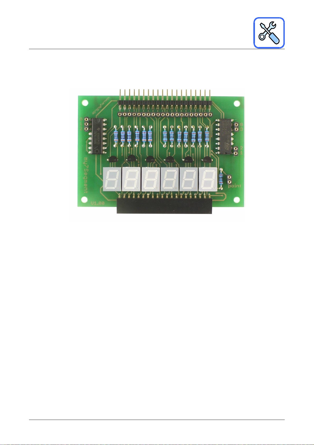
Bestücktes my7-Segment Add-On
Assembled my7-segment add-on
Weiterführende Informationen
Garantiebestimmungen
Das Bauelementesortiment wurde gewissenhaft
zusammengestellt und auf Vollzähligkeit überprüft. Für
Fehler beim Bestücken der Leiterplatte leisten wir keinen
Ersatz. Beschädigte Bauelemente ersetzen wir Ihnen auf
Anfrage. Für fehlerhaften und/oder vorschriftswidrigen
Einsatz des Boards übernehmen wir keine Garantie
Hilfen und weitere Informationen
Weitere Informationen zu unserem Produkt erhalten Sie
auf unserer Internetseite www.myavr.de
Bei Fragen
bzw. unsere Hotline 03585-470222.
Die aktuellsten Dokumente zum my7-Segment Add-On finden Sie unter
The latest documents for the my7-segment add-on you can find at our homepage www.myAVR.com under
„Download“.
Abbildungen können vom Inhalt abweichen. Änderungen im Sinne des technischen Fortschrittes behält sich der
Hersteller vor.
Images may vary from the content. The manufacturers retains changes in terms of technical advances.
Further information
Acceptance of guarantee
The electronic components have been assorted carefully
and the completeness has been checked. We don’t
substitute components when you have made a mistake by
the assembling. On request we will replace defect
component parts. For damage caused by incorrect usage
respectively assembly or usage contrary to general
regulations we do not accept any guarantee.
Support and more information
For more information please visit our homepage at
www.myavr.com
If you have any questions feel free to contact us under
www.myAVR.de im Downloadbereich.
www.myAVR.de © Laser & Co. Solutions GmbH - 06/2010 www.myAVR.com
 Loading...