

Page 1
myAVR
technical description
myAVR
myAVRmyAVR
Technische Beschreibung
my7-Segment Add-On 1.0
Inhalt Contents
Allgemeine Beschreibung...............................................3
Eigenschaften.............................................................3
Technische Daten ..........................................................4
Betriebsdaten .............................................................4
Mechanische Daten .......................................................4
Schaltplan...................................................................4
Pinbelegung................................................................4
Bestückungsplan ........................................................5
Bestücktes Board .......................................................5
Ansteuerung...................................................................6
Anwendungsbeispiel ......................................................7
Allgemeine Sicherheitshinweise.....................................7
General description........................................................3
Properties................................................................... 3
Technical Data............................................................... 4
Operating Data........................................................... 4
Mechanical Data ............................................................4
Circuit diagram ...........................................................4
Pinlayout.....................................................................4
Layout diagram...........................................................5
Board, equipped......................................................... 5
Programming.................................................................. 6
Example of use ..............................................................7
Safety Guidelines...........................................................7
www.myAVR.de
© Laser & Co. Solutions GmbH – 05/2010 www.myAVR.com
Page 2

Seite: 2/7 Technische Beschreibung my7-Segment Add-On 1.0
Die Informationen in diesem Produkt werden ohne
Rücksicht auf einen eventuellen Patentschutz
veröffentlicht.
Warennamen werden ohne Gewährleistung der freien
Verwendbarkeit benutzt.
Bei der Zusammenstellung von Texten und Abbildungen
wurde mit größter Sorgfalt vorgegangen.
Trotzdem können Fehler nicht vollständig
ausgeschlossen werden.
Die Autoren können für fehlerhafte Angaben und deren
Folgen weder eine juristische Verantwortung noch
irgendeine Haftung übernehmen.
Für Verbesserungsvorschläge und Hinweise auf Fehler
sind die Autoren dankbar.
In spite of the great care taken while writing this
document the author is not responsible for the topicality,
correctness, completeness or quality of the information
provided. Liability claims regarding damage caused by
the use of any information provided, including any kind of
information which is incomplete or incorrect,will therefore
be rejected.
Alle Rechte vorbehalten, auch die der fotomechanischen
Wiedergabe und der Speicherung in elektronischen
Medien.
Die gewerbliche Nutzung der in diesem Produkt
gezeigten Modelle und Arbeiten ist nicht zulässig.
All rights reserved. Unless otherwise specified, no part of
this publication may be reproduced or utilized in any form
or by any means, electronic or mechanical, including
photocopying and microfilm, without permission in writing
from the publisher.
Fast alle Hardware- und Softwarebezeichnungen, die in
diesem Dokument erwähnt werden, sind gleichzeitig auch
All trademarks and registered trademarks appearing in
this document are the property of their respective owners.
eingetragene Warenzeichen und sollten als solche
betrachtet werden.
© Laser & Co. Solutions GmbH
Promenadenring 8
02708 Löbau
Deutschland
www.myAVR.de
Tel: ++49 (0) 358 470 222
Fax: ++49 (0) 358 470 233
© Laser & Co. Solutions GmbH
Promenadenring 8
02708 Löbau
Germany
www.myAVR.com
Tel: ++49 (0) 358 470 222
Fax: ++49 (0) 358 470 233
www.myAVR.de © Laser & Co. Solutions GmbH - 05/2010 www.myAVR.com
Page 3
Technische Beschreibung my7-Segment Add-On 1.0 Seite: 3/7
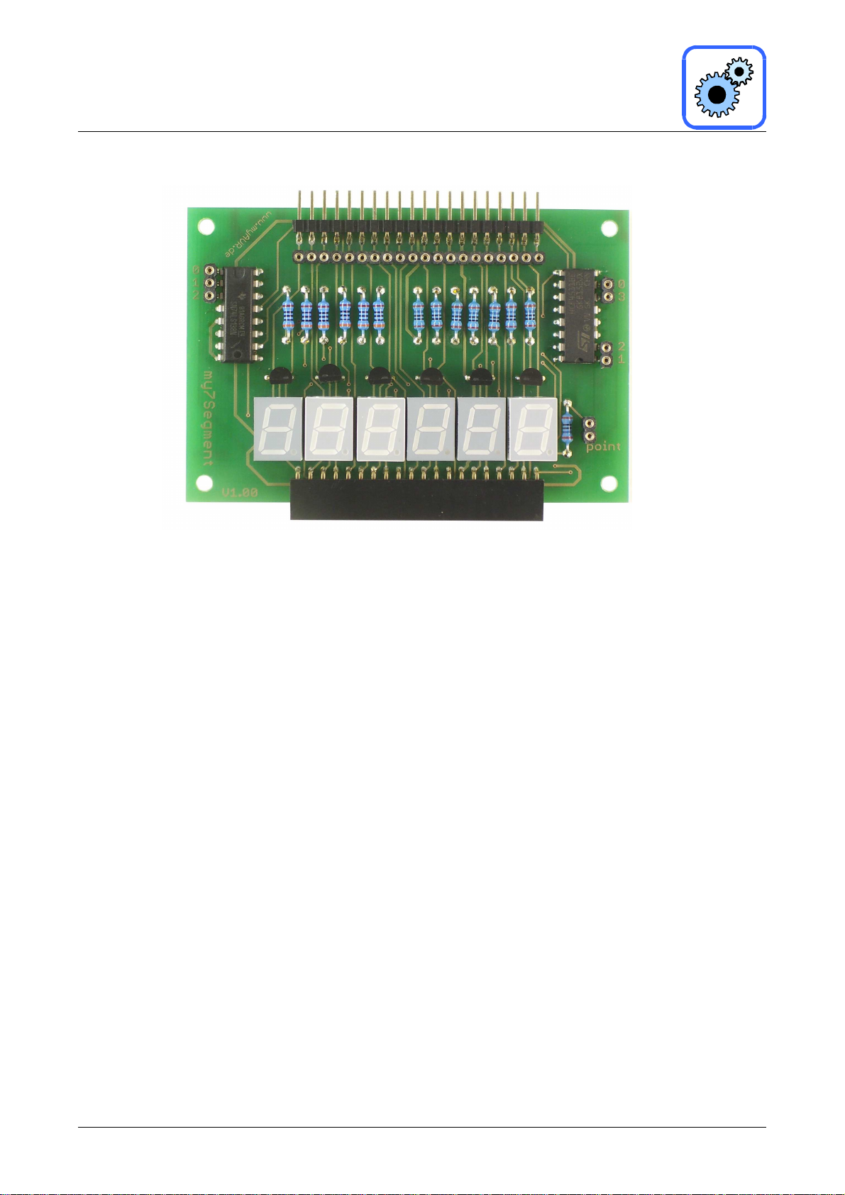
Allgemeine Beschreibung
Das my7-Segment Add-On ist ein anschlussfertiges
Erweiterungsmodul, welches direkt über die
standardisierte Steckerleiste mit den myAVR Boards
verbunden werden kann.
Die Ansteuerung kann über ein myAVR Board oder über
ein mySmartControl erfolgen. Die Erweiterung mit
zusätzlichen Add-Ons aus der myAVR-Serie ist möglich.
Jede 7-Segment-Anzeige kann jeweils die Ziffern 0-9 darstellen. Es gehören 6 Anzeigen zu diesem Add-On. Es ist
robust und auf die myAVR-Serie abgestimmt.
Eigenschaften
• 6x 7-Segment-Anzeige
• Jede 7-Segment-Anzeige kann die Ziffern 0-9
darstellen
• Freie Wahl der Verbindungen über die Sockelleisten
mittels Patchkabel
• Segmente sind einzeln ansteuerbar
• Steckerleiste für den Anschluss an ein myAVR Board
• Buchsenleiste für den Anschluss weiterer Module
• Leiterplatte gebohrt, verzinnt, Industriefertigung,
robust, bedruckt
General description
The my7-segment add-on is an extension module which
you can connect directly with the myAVR board via the
multi-pin connector.
You can activate it via a myAVR board or via a
mySmartControl. You can also expand the module with
other add-ons from the myAVR series.
Every 7-segment display can display the numbers 0-9.
This add-on has 6 7-segment displays. It is robust and
aligned to the myAVR series.
Properties
• 6x 7-segment display
• Every 7-segment add-on can display the numbers
0-9
• You can activate the segments separately
• Free choice of connections on the pin header male
through patch cable
• multi-pin connector for the connection with a
myAVR Board
• Female connector for the connection with other
modules
• Printed circuit board pre-drilled, tin-plated, industrial
production, solid, printed
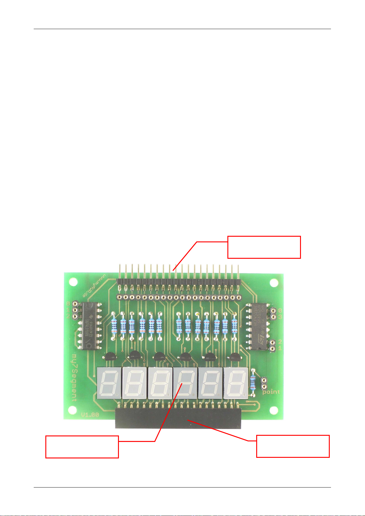
myAVR Board-Verbinder
myAVR Board connector
6x 7-Segment-Anzeige
6x 7-segment display
www.myAVR.de © Laser & Co. Solutions GmbH - 05/2010 www.myAVR.com
Erweiterungsbuchse
add-on-socket
Page 4

Seite: 4/7 Technische Beschreibung my7-Segment Add-On 1.0
Technische Daten
Betriebsdaten
Betriebsstrom < 500 mA
Betriebsspannung 4,5 V - 5,2 V
Betriebstemperatur 0 °C bis 70 °C
Lagertemperatur -65 °C bis 150 °C
Mechanische Daten
Abmessungen Platine
(L x B x H)
Masse ca. 36 g
Rastermaß 2,54 mm
Leiterplattenmaterial FR4; 0,35 µm Cu
Schaltplan
90 mm x 60 mm x 1,5 mm
Technical Data
Operating Data
Operating Current < 500 mA
Operating Voltage 4,5 V - 5,2 V
Operating Temperature 0 °C to 70 °C
Storage Temperature -65 °C to 150 °C
Mechanical Data
Dimensions of the board
(L X B X H)
Weight ca. 36 g
Grid dimensions 2,54 mm
PCB material FR4; 0,35 µm Cu
Circuit diagram
90 mm x 60 mm x 1,5 mm
Pinbelegung
Pin Nummer /
Pin No.
3
4
5
7, 1, 2, 6
8
13, 12, 11, 10,
9, 15, 14
16 VCC
www.myAVR.de © Laser & Co. Solutions GmbH - 05/2010 www.myAVR.com
Pinlayout
Symbol /
symbol
LT¯
BI¯
LE¯
Name und Funktion /
Name and Function
Funktionstest (LOW-Aktiv)
Lamp test input (active LOW)
Adressdeaktivierung (LOW-Aktiv)
Ripple blanking input (active LOW)
Taktfrequenzeingang
latch enable inputs
D1 to D4 BCD Adressierung
BCD adress inputs
GND
Masse (0 V)
ground (0 V)
Qa to Qg Segmentausgabe
segmentes outputs
Positive Versorgungsspannung
positive supply voltage
Page 5

Technische Beschreibung my7-Segment Add-On 1.0 Seite: 5/7
Bestückungsplan
Layout diagram
Bestücktes Board
Board, equipped
www.myAVR.de © Laser & Co. Solutions GmbH - 05/2010 www.myAVR.com
Page 6

Seite: 6/7 Technische Beschreibung my7-Segment Add-On 1.0
Ansteuerung
Die Ansteuerung des my7-Segment Add-On erfolgt über
den BCD-zu-7-Segment-Decoder und den Demultiplexer.
Zur Ansteuerung ist es nötig, die Verbindung zwischen der
7-Segment-Anzeige, dem Decoder und Multiplexer
herzustellen.
Funktionstabelle des 74HC4511
Programming
The activation of the my7-segment add-on happens via
the BCD-to-7-segment decoder and the demultiplexer. To
control it is necessary to make the connection between the
7-segment display, the decoder and multiplexer.
Function Table 74HC4511
__
LE
__
BI
INPUTS OUTPUTS
__
D4 D3 D2 D1 Qa Qb Qc Qd Qe Qf Qg
LT
DISPLAY
X X L X X X X H H H H H H H 8
X L H X X X X L L L L L L L blank
L H H L L L L H H H H H H L 0
L H H L L L H L H H L L L L 1
L H H L L H L H H L H H L H 2
L H H L L H H H H H H L L H 3
L H H L H L L L H H L L H H 4
L H H L H L H H L H H L H H 5
L H H L H H L L L H H H H H 6
L H H L H H H H H H L L L L 7
L H H H L L L H H H H H H H 8
L H H H L L H H H H L L H H 9
L H H H L H L L L L L L L L blank
L H H H L H H L L L L L L L blank
L H H H H L L L L L L L L L blank
L H H H H L H L L L L L L L blank
L H H H H H L L L L L L L L blank
L H H H H H H L L L L L L L blank
H H H X X X X
1. Ist abhängig vom verwendeten BCD-Code während der
______________
LOW-zu-HIGH Übertragung von LE.
L = LOW voltage Level
H = HIGH voltage Level
X = Don’t Care
Dem BCD-zu-7-Segment-Decoder übergibt man die Zahl,
die man auf der 7-Segment-Anzeige ausgeben möchte.
Es ist nur sinnvoll Werte von 0 bis 9 zu übergeben, da die
7-Segment-Anzeige sonst nichts ausgibt.
Funktionstabelle des DM74LS138
1. Depends upon the BCD-code applied during the LOW-to-
______________ ___-
HIGH transition of LE.
L = LOW voltage Level
H = HIGH voltage Level
X = Don’t Care
You give a number to the BCD-to-7-segment decoder
which you want to display on the 7-segment display. It
only makes sense to give them values between 0 and 9
because otherwise the 7-segment display shows nothing.
Function Table DM74LS138
(1)
Inputs
Enable Select
Outputs
G1 G2 (Note 1) C B A Y0 Y1 Y2 Y3 Y4 Y5 Y6 Y7
X H X X X H H H H H H H H
L X X X X H H H H H H H H
H L L L L L H H H H H H H
H L L L H H L H H H H H H
H L L H L H H L H H H H H
H L L H H H H H L H H H H
H L H L L H H H H L H H H
H L H L H H H H H H L H H
H L H H L H H H H H H L H
H L H H H H H H H H H H L
H = HIGH Level
L = LOW Level
X = Don’t Care
Note 1: G2 =G2A+G2B
Über den Demultiplexer wählt man aus, auf welcher
7-Segment-Anzeige man die Zahl darstellen möchte.
Dabei werden die 7-Segment-Anzeigen von vorn gezählt,
d.h. die linke 7-Segment-Anzeige hat die Nummer 0.
Via the Demultiplexer you can choose on which
7-segment display you want to have the number. The 7segment displays are counted from the front. That means
that the left 7-segment display has the number 0.
(1)
www.myAVR.de © Laser & Co. Solutions GmbH - 05/2010 www.myAVR.com
Page 7

Technische Beschreibung my7-Segment Add-On 1.0 Seite: 7/7
Abbildung
/
picture:
Anwendungsbeispiel
Example of use
Zähler mit mySmartControl
Counter with mySmartControl
Allgemeine Sicherheitshinweise
Grundsätzlich ist my7-Segment nur zum Einsatz unter
Lern- und Laborbedingungen konzipiert. Er ist nicht
vorgesehen und nicht dimensioniert zur Steuerung realer
Anlagen. Bei vorschriftsmäßigem Anschluss und Betrieb
treten keine lebensgefährlichen Spannungen auf. Beachten
Sie trotzdem die Vorschriften, die beim Betrieb elektrischer
Geräte und Anlagen Gültigkeit haben. Wir versichern, dass
die Leiterplatte durch den Hersteller getestet wurde. Für
fehlerhaften und/oder vorschriftswidrigen Einsatz des
Boards übernehmen wir keine Garantie.
Die aktuellsten Dokumente zum my7-Segment finden Sie unter www.myAVR.de im Downloadbereich.
The latest documents for the my7-segment you can find at our homepage www.myAVR.com under „Download“.
Abbildungen können vom Inhalt abweichen. Änderungen im Sinne des technischen Fortschrittes behält sich der
Hersteller vor.
Images may vary from the content. The manufacturers retains changes in terms of technical advances.
Safety Guidelines
my7-Segment is designed for educational and experimental
use only. It is not intended and not dimensioned to control
real industrial facilities. At correct use there will not occur
extremely dangerous voltages. Nevertheless, be aware of
general guidelines for using electronic devices. We assure
that the PCB has been tested by the producer. For
incorrect use and/or application contrary to technical
regulations we are not liable.
.
www.myAVR.de © Laser & Co. Solutions GmbH - 05/2010 www.myAVR.com
 Loading...