

MyAmplifiers Nikrans NS-1000 3G Installation Manual
1
MyAmplifiers.com - +44 977215553 (UK) , +33 977215553 (France),
E-mail: contact@myamplifiers.com - Skype: gsm_amplifier www.myamplifiers.com
INSTALLATION GUIDE
3G Mobile Signal Repeater
Nikrans NS-1000 3G model
3G connection | 2100MHz
Coverage: 1000 m2
Contents
1. Purposes
2. Technical features
3. Technical specifications
4. System configuration
5. Operation instructions
5.1. Descriptions of the overall dimension of the
equipment
5.2. Instructions on installation
5.3. Debugging and commissioning
5.4. System maintenance
6. Descriptions on maintenance
6.1. Faults and failures
6.2. Troubleshooting

2
MyAmplifiers.com - +44 977215553 (UK) , +33 977215553 (France),
E-mail: contact@myamplifiers.com - Skype: gsm_amplifier www.myamplifiers.com
Nikrans NS-10003G Signal Booster
1. Purpose
As the domestic mobile communication industry
develops rapidly, the amount of mobile communications
users increases so steadily that the cell planning gets
smaller and smaller while the base station positions get
lower and lower. On the other hand, as city construction
develops, more and more high-rise buildings are set up
constantly, based on the shadow effect of the radio
propagation, the mobile communications may get a signal
blind spot behind or between the buildings. Moreover, in
order to avoid interference from adjacent districts, the main
lobe of the antenna radiation orientation of the cell mobile
communication base station in construction has a bigger
down-tilt obliquity, thus the signals usually can not be
received effectively in the high and medium parts of the
high rise buildings. Furthermore, due to the shield effect to
electro-magnetic waves caused by buildings, the mobile
communication signals cannot be received in tunnels,
subways, underground stores, entertainment complex,
parking fields, hotels, office buildings and other large-size
and closed buildings.
Signal amplifier is an effective device that makes up
the insufficient base station coverage in the mobile network,
enlarges the coverage area of the base station and fills in
the blind spots, which adopts double-ended duplex design
and external power supply with advantages of convenient
mounting and high reliability. The bandwidth of the signal
amplifier may cover GSM 25MHz/19 MHz/ 6MHz,
CDMA10MHz/DCS75 MHz with compatibility between
digital system and analogue system.
2. Technical features
High system gains
Full duplex and double-end design, external power
supply, and convenient installation
ALC technology with auto-steady function adopted.
Provide power indication and uplink and downlink
indications.
With the amplified linear power, the intermodulation and
spuriousness are suppressed effectively.
The reliability conforms to GB6993-86 standards.
The electromagnetic compatibility conforms to ETS300
609-4 standards.
3
MyAmplifiers.com - +44 977215553 (UK) , +33 977215553 (France),
E-mail: contact@myamplifiers.com - Skype: gsm_amplifier www.myamplifiers.com
3. Technical 3G Signal Booster specification
Specification
Frequency
range(MHz)
Up link
1920-1980
Downlink
2110-2170
Gain(dB)
Up link
65
Downlink
70
Output power(dBm)
15
Pass band ripple
≤5dB
Guard band rejection
(BW-60dB)≤42 MHz(BW-70dB)≤45 MHz
I/O impedance
50/N Connector
I/O return loss
≤-10dB
Noise figure
≤8dB
Intermodulation attenuation
(Po=5dBm)
≥38dBc
Transmission Delay
≤0.5us
Ambient temperature
-10℃~50℃
Power supply
AC110~220V±10% 45~55Hz
Size
158mm*136mm*37mm
Reliability
To the GB6993-86 standard
Electromagnetic
compatibility
To the ETS300 694-4 standard
Function
a) Power supply LED denote
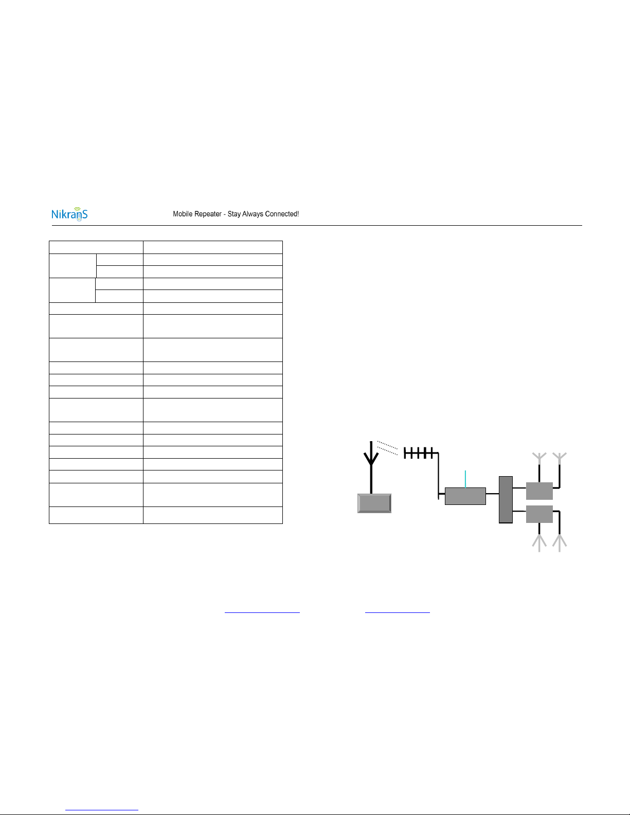
4. System structure
A simple signal amplifier system is composed of a host
signal amplifier, reverse antenna and in-door covering
system. Reverse antenna aims at the reverse base station
that requires for expanding the coverage, the BTS Port of
the host signal amplifier is connected with reverse antenna
and User’s Port is connected with in-door covering system.
As shown in the following diagram, firstly, the indoor signals
introduced by the signal amplifier are divided into two-way
signals by splitters, then each signal is distributed two
antennas through a coupler with the power distribution ratio
equal to circuit exhaust ratio so as to ensure both of the
antennas to obtain equal power (splitter and coupler may
can be configured flexibility). It shall be attached importance
that at least 15dB of the isolation shall be bigger than the
plus between reverse antenna and covering system for
meeting the requirements of C/I≥15dB of the
GSM/CDMA/DCS/PCS system.
220V
System structure diagram
BTS
Signal amplifier
splitter
Coupler
Coupler
 Loading...